Service Manual
Page 1
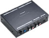
... oz.) Supplied accessories BUS cable RCA pin cord Velcro tape Design and specifications are subject to a Sony BUS system-compatible master unit. Enjoy the sound of Sony Corporation. 9-873-500-12 2002H0500-1 C 2002.08 Sony Corporation e Vehicle Company Published by Sony Engineering Corporation AUX-IN SELECTOR SERVICE MANUAL Ver 1.1 2002.08 XA-300 US Model Canadian Model AEP Model UK Model E Model SPECIFICATIONS Power requirement 12 V DC car battery (negative earth) Current drain 340 mA Operating temperature -10°...
... oz.) Supplied accessories BUS cable RCA pin cord Velcro tape Design and specifications are subject to a Sony BUS system-compatible master unit. Enjoy the sound of Sony Corporation. 9-873-500-12 2002H0500-1 C 2002.08 Sony Corporation e Vehicle Company Published by Sony Engineering Corporation AUX-IN SELECTOR SERVICE MANUAL Ver 1.1 2002.08 XA-300 US Model Canadian Model AEP Model UK Model E Model SPECIFICATIONS Power requirement 12 V DC car battery (negative earth) Current drain 340 mA Operating temperature -10°...
Service Manual
Page 2
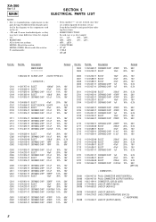
DIAGRAMS 3-1. IC Pin Function Description 6 4. SET MASTER UNIT BUS CONTROL OUTPUT terminal BUS CONTROL INPUT terminal Therefore, to repair This set is controled by heat. 2 ELECTRICAL PARTS LIST 8 SECTION 1 SERVICING NOTES Connection to operate this set can be dam- Mac OS 8.6 or later (Mac OS 9.0 or later recommended) Notes on chip component replacement • Never reuse a disconnected chip component. • Notice that the minus side of a tantalum capacitor may be connected via...
DIAGRAMS 3-1. IC Pin Function Description 6 4. SET MASTER UNIT BUS CONTROL OUTPUT terminal BUS CONTROL INPUT terminal Therefore, to repair This set is controled by heat. 2 ELECTRICAL PARTS LIST 8 SECTION 1 SERVICING NOTES Connection to operate this set can be dam- Mac OS 8.6 or later (Mac OS 9.0 or later recommended) Notes on chip component replacement • Never reuse a disconnected chip component. • Notice that the minus side of a tantalum capacitor may be connected via...
Service Manual
Page 3
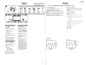
... would be subject to AUX IN 1, and connect a portable device (such as from direct sunlight or hot air from the heater. - For the playback method of the selected device, refer to its operating manual. 4 Adjust the volume of the master unit to select "USB." 2 Open the playback software (Windows Media Player, etc.) on AUX IN 1 and AUX IN 2, connect the Sony car audio DVD changer to : - As the sound output differs on your nearest...
... would be subject to AUX IN 1, and connect a portable device (such as from direct sunlight or hot air from the heater. - For the playback method of the selected device, refer to its operating manual. 4 Adjust the volume of the master unit to select "USB." 2 Open the playback software (Windows Media Player, etc.) on AUX IN 1 and AUX IN 2, connect the Sony car audio DVD changer to : - As the sound output differs on your nearest...
Service Manual
Page 4
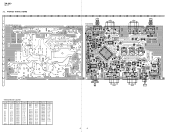
...ZD405 ZD406 E-14 D-13 D-13 D-13 F-13 B-14 B-14 C-14 C-14 C-14 B-22 Ref. PRINTED WIRING BOARD 1 2 3 4 5 6 7 8 9 10 11 12 13 14 15 16 17 18 19 20 21 22 23 CN101 CN102 INPUT OUTPUT CONTROL CN104 CN108 CONTROL A INPUT OUTPUT R AUDIO L R AUDIO L MAIN BOARD (COMPONENT SIDE) B C D E F G H I -20 C-20 C-19 4 4 Q102... R716 R714 IC7 C709 C710 R711 R712 RV101 VOL R713 C712 C711 C721 11 1-682-009- (11) J CN103 USB R CN106 L AUX IN 2 AUDIO CN105 R L AUX IN 1 AUDIO CN107 HEADPHONE i • Semiconductor Location Ref. XA-300 Ver 1.1 3-2.
...ZD405 ZD406 E-14 D-13 D-13 D-13 F-13 B-14 B-14 C-14 C-14 C-14 B-22 Ref. PRINTED WIRING BOARD 1 2 3 4 5 6 7 8 9 10 11 12 13 14 15 16 17 18 19 20 21 22 23 CN101 CN102 INPUT OUTPUT CONTROL CN104 CN108 CONTROL A INPUT OUTPUT R AUDIO L R AUDIO L MAIN BOARD (COMPONENT SIDE) B C D E F G H I -20 C-20 C-19 4 4 Q102... R716 R714 IC7 C709 C710 R711 R712 RV101 VOL R713 C712 C711 C721 11 1-682-009- (11) J CN103 USB R CN106 L AUX IN 2 AUDIO CN105 R L AUX IN 1 AUDIO CN107 HEADPHONE i • Semiconductor Location Ref. XA-300 Ver 1.1 3-2.
Service Manual
Page 5
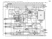
...XA-300 Ver 1.1 CN101 NC 8P INPUT CONTROL CN103 4P USB GND D+ DVBUS CN104 2P L INPUT AUDIO R CN105 2P L AUX IN 2 R CN106 2P L AUX...R203 47k R204 47k Q402 DTA144EK BUS ON SWITCH BUS INTERFACE (FOR SONY BUS) R406 10 R407 10 R408 10... C108 47 16V C109 0.1 C110 0.1 RESET SIGNAL GENERATOR NCO NCO NCO NCO NCO RESET EXTAL XTAL GND VL VLC3 VLC2 VLC1 NCO...MODE SW NIL USB ON NCO POWER ON NCO BUS CLK BUS SI BUS SO NCO NCO LINK OFF NCO ATT NCO AUDIO SEL1 NCO AUDIO SEL2 NCO AUDIO SEL3 NCO NCO NCO NCO SYSTEM CONTROLLER IC1 CXP83412-054Q NIL BUS ON BU CHECK NCO NCO NC SUB CLOCK SUB CLOCK...
...XA-300 Ver 1.1 CN101 NC 8P INPUT CONTROL CN103 4P USB GND D+ DVBUS CN104 2P L INPUT AUDIO R CN105 2P L AUX IN 2 R CN106 2P L AUX...R203 47k R204 47k Q402 DTA144EK BUS ON SWITCH BUS INTERFACE (FOR SONY BUS) R406 10 R407 10 R408 10... C108 47 16V C109 0.1 C110 0.1 RESET SIGNAL GENERATOR NCO NCO NCO NCO NCO RESET EXTAL XTAL GND VL VLC3 VLC2 VLC1 NCO...MODE SW NIL USB ON NCO POWER ON NCO BUS CLK BUS SI BUS SO NCO NCO LINK OFF NCO ATT NCO AUDIO SEL1 NCO AUDIO SEL2 NCO AUDIO SEL3 NCO NCO NCO NCO SYSTEM CONTROLLER IC1 CXP83412-054Q NIL BUS ON BU CHECK NCO NCO NC SUB CLOCK SUB CLOCK...
Service Manual
Page 6
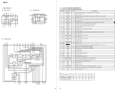
... signal input terminal "H": active 79 BUS_ON I Bus on/off control signal input from the SONY bus interface (IC2) 80 NIL I Not used (fixed at "L") 3 USB_ON O USB power supply switch (Turn on the power when USB in this set) 2 NIL I Not used (open ) 75 NC - Power supply terminal (+5V) 73 SUB CLOCK O Sub system clock output terminal Not used (fixed at "L") *1 Source mode Terminal AUDIO_SEL1 (pin qh) AUDIO_SEL2 (pin qk) AUX1 "H" "H" AUX2 "L" "L" USB "L" "H" CD-C "H" "L" 6 6 DAC WRCLK FIFO 8X OVERSAMPLING LEVEL...
... signal input terminal "H": active 79 BUS_ON I Bus on/off control signal input from the SONY bus interface (IC2) 80 NIL I Not used (fixed at "L") 3 USB_ON O USB power supply switch (Turn on the power when USB in this set) 2 NIL I Not used (open ) 75 NC - Power supply terminal (+5V) 73 SUB CLOCK O Sub system clock output terminal Not used (fixed at "L") *1 Source mode Terminal AUDIO_SEL1 (pin qh) AUDIO_SEL2 (pin qk) AUX1 "H" "H" AUX2 "L" "L" USB "L" "H" CD-C "H" "L" 6 6 DAC WRCLK FIFO 8X OVERSAMPLING LEVEL...
Service Manual
Page 7
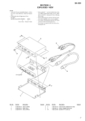
... Appearance Parts Example: KNOB, BALANCE (WHITE) . . . (RED) ↑ ↑ Parts Color Cabinet's Color SECTION 4 EXPLODED VIEW • Items marked "*" are not stocked since they are given in the last of the electrical parts list. #1 2 #1 3 5 #1 XA-300 not supplied 1 Ref. No. 4 5 #1 Part No. No. 1 2 3 Part No. Some delay should be anticipated when ordering these items. • The mechanical parts with no reference number in...
... Appearance Parts Example: KNOB, BALANCE (WHITE) . . . (RED) ↑ ↑ Parts Color Cabinet's Color SECTION 4 EXPLODED VIEW • Items marked "*" are not stocked since they are given in the last of the electrical parts list. #1 2 #1 3 5 #1 XA-300 not supplied 1 Ref. No. 4 5 #1 Part No. No. 1 2 3 Part No. Some delay should be anticipated when ordering these items. • The mechanical parts with no reference number in...
Service Manual
Page 8
... CN104 CN105 1-580-907-31 PLUG, CONNECTOR (INPUT CONTROL) 1-580-907-31 PLUG, CONNECTOR (OUTPUT CONTROL) 1-815-194-11 CONNECTOR, USB (B) (USB) 1-778-940-11 JACK 2P (INPUT AUDIO) 1-764-593-21 JACK 2P (AUX IN 2) CN106 CN107 CN108 1-764-593-21 JACK 2P (AUX IN 1) 1-764-270-21 JACK, STEREO MINIATURE (DIA.3.5) (i HEADPHONE) 1-778-940-11 JACK 2P (OUTPUT AUDIO) 8 C604 C605 Part No. Some delay should be...
... CN104 CN105 1-580-907-31 PLUG, CONNECTOR (INPUT CONTROL) 1-580-907-31 PLUG, CONNECTOR (OUTPUT CONTROL) 1-815-194-11 CONNECTOR, USB (B) (USB) 1-778-940-11 JACK 2P (INPUT AUDIO) 1-764-593-21 JACK 2P (AUX IN 2) CN106 CN107 CN108 1-764-593-21 JACK 2P (AUX IN 1) 1-764-270-21 JACK, STEREO MINIATURE (DIA.3.5) (i HEADPHONE) 1-778-940-11 JACK 2P (OUTPUT AUDIO) 8 C604 C605 Part No. Some delay should be...
Service Manual
Page 10
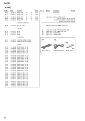
...MANUAL, INSTRUCTION (ENGLISH, FRENCH, ITALIAN, GERMAN, DUTCH, PORTUGUESE, RUSSIAN, SWEDISH, SPANISH, TRADITIONAL CHINESE) RV101 1-227-432-11 RES, VAR (VOL) < RELAY > RY101 1-515-762-11 RELAY RY102 1-515-762-11 RELAY RY103 1-515-762-11 RELAY PARTS FOR INSTALLATION AND CONNECTION 501 1-590-519-72 CORD (WITH CONNECTOR) (BUS) 502 1-696-287-41 CORD, CONNECTION...18B 8-719-056-84 DIODE UDZSTE-177.5B 8-719-056-77 DIODE UDZ-TE-17-3.9B BUS CABLE × 1 RCA PIN CORD × 1 504 MAGIC TAPE × 2 ZD401 ZD402 ZD403 ZD404 ZD405 8-719-069-... UDZ-TE-17-3.9B 10 XA-300 MAIN Ref. No.
...MANUAL, INSTRUCTION (ENGLISH, FRENCH, ITALIAN, GERMAN, DUTCH, PORTUGUESE, RUSSIAN, SWEDISH, SPANISH, TRADITIONAL CHINESE) RV101 1-227-432-11 RES, VAR (VOL) < RELAY > RY101 1-515-762-11 RELAY RY102 1-515-762-11 RELAY RY103 1-515-762-11 RELAY PARTS FOR INSTALLATION AND CONNECTION 501 1-590-519-72 CORD (WITH CONNECTOR) (BUS) 502 1-696-287-41 CORD, CONNECTION...18B 8-719-056-84 DIODE UDZSTE-177.5B 8-719-056-77 DIODE UDZ-TE-17-3.9B BUS CABLE × 1 RCA PIN CORD × 1 504 MAGIC TAPE × 2 ZD401 ZD402 ZD403 ZD404 ZD405 8-719-069-... UDZ-TE-17-3.9B 10 XA-300 MAIN Ref. No.
Service Manual
Page 12
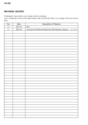
Ver. XA-300 REVISION HISTORY Clicking the version allows you to jump to the revised page. Also, clicking the version at the upper right on the revised page allows you to jump to the next revised page. Date Description of Revision 1.0 2001.03 New 1.1 2002.08 Correction of Printed wiring board and Schematic diagram (ECN-CSA05650)
Ver. XA-300 REVISION HISTORY Clicking the version allows you to jump to the revised page. Also, clicking the version at the upper right on the revised page allows you to jump to the next revised page. Date Description of Revision 1.0 2001.03 New 1.1 2002.08 Correction of Printed wiring board and Schematic diagram (ECN-CSA05650)


