

Limited Warranty (U.S. Only)
Page 1
... acts of God, accident, misuse, abuse, negligence, commercial use, or modification of, or to any part of five (5) years. SONY SHALL NOT BE LIABLE FOR ANY INCIDENTAL OR CONSEQUENTIAL DAMAGES FOR BREACH OF ANY EXPRESS OR IMPLIED WARRANTY ON THIS PRODUCT. This warranty gives...341-02 General Stereo/Hifi Components/Tape Decks ® CD Players/Mini Disc Players/Audio Systems LIMITED WARRANTY Hifi Audio ES Products Sony Electronics Inc. ("Sony") warrants this Product is determined to be presented to obtain warranty service. This warranty is invalid if the factory applied serial ...
... acts of God, accident, misuse, abuse, negligence, commercial use, or modification of, or to any part of five (5) years. SONY SHALL NOT BE LIABLE FOR ANY INCIDENTAL OR CONSEQUENTIAL DAMAGES FOR BREACH OF ANY EXPRESS OR IMPLIED WARRANTY ON THIS PRODUCT. This warranty gives...341-02 General Stereo/Hifi Components/Tape Decks ® CD Players/Mini Disc Players/Audio Systems LIMITED WARRANTY Hifi Audio ES Products Sony Electronics Inc. ("Sony") warrants this Product is determined to be presented to obtain warranty service. This warranty is invalid if the factory applied serial ...
Primary User Manual
Page 2
... set out in a residential installation. When the control S cord connection causes interference to rain or moisture. TA-E2000ESD For the customers in the space provided below. Refer to the TA-E2000ESD as possible. NO USERSERVICEABLE PARTS INSIDE. It has been type tested and found to comply with the limits...with the Class B limits for additional suggestions. Wind the cord around it as close to these numbers whenever you call upon your Sony dealer regarding this equipment does cause interference to radio or television reception, which are on , the user is intended to alert the...
... set out in a residential installation. When the control S cord connection causes interference to rain or moisture. TA-E2000ESD For the customers in the space provided below. Refer to the TA-E2000ESD as possible. NO USERSERVICEABLE PARTS INSIDE. It has been type tested and found to comply with the limits...with the Class B limits for additional suggestions. Wind the cord around it as close to these numbers whenever you call upon your Sony dealer regarding this equipment does cause interference to radio or television reception, which are on , the user is intended to alert the...
Primary User Manual
Page 3
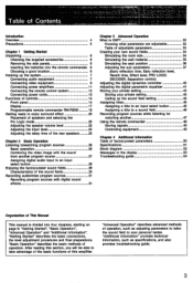
T able of operation. "Additional Information" provides technical information, such as adjusting parameters to tailor the sound field to your private setting 43 Functions of controls 14 Calling up the sound field setting 44 Front panel 14 Assigning titles 45 Display 17 Assigning a title to an input select button 45 Programmable remote commander RM-P2000 18 Assigning a title to a sound field 46 Getting ready to enjoy surround effect 20 Recording program sources while listening to/ Placement of speakers and selecting the watching another 47 Pro Logic mode 20 Using the ...
T able of operation. "Additional Information" provides technical information, such as adjusting parameters to tailor the sound field to your private setting 43 Functions of controls 14 Calling up the sound field setting 44 Front panel 14 Assigning titles 45 Display 17 Assigning a title to an input select button 45 Programmable remote commander RM-P2000 18 Assigning a title to a sound field 46 Getting ready to enjoy surround effect 20 Recording program sources while listening to/ Placement of speakers and selecting the watching another 47 Pro Logic mode 20 Using the ...
Primary User Manual
Page 4
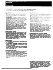
... gate effect (Refer to page 8.) In particular, the design principles of the following patents: U.S. numbers 3,632,886, 3,746,792, and 3,959,590. Introduction Overview The TA-E2000ESD is a control amplifier with Dolby Surround. Digital Surround • This amplifier electronically reproduces the reflected sound and reverberative sound by using its digial signal processor...
... gate effect (Refer to page 8.) In particular, the design principles of the following patents: U.S. numbers 3,632,886, 3,746,792, and 3,959,590. Introduction Overview The TA-E2000ESD is a control amplifier with Dolby Surround. Digital Surround • This amplifier electronically reproduces the reflected sound and reverberative sound by using its digial signal processor...

Primary User Manual
Page 5
... the plug. On operation Before making program source connections, be used for the purpose of safety and will fit into the outlet, contact your nearest Sony dealer. 5 For the customers in the U.S.A. On cleaning the cabinet Clean the cabinet, panel and controls with a soft cloth lightly moistened with mild detergent solution...
... the plug. On operation Before making program source connections, be used for the purpose of safety and will fit into the outlet, contact your nearest Sony dealer. 5 For the customers in the U.S.A. On cleaning the cabinet Clean the cabinet, panel and controls with a soft cloth lightly moistened with mild detergent solution...

Primary User Manual
Page 6
... system for the proper operation of the screws that the following accessories are run down, the remote commander will be expected about a half year using Sony SUM-3 (NS). In this case, replace the batteries with adequate air circulation. When the batteries are present. MIIRIMEMI yam.• Chapter 1 Getting Started ... and install the batteries in a location with new ones. Do not place anything on top of its components. Remote commander RM-P2000 (1) Sony battery SUM-3 (NS) (2) Audio connecting cord (3) Screw (4) Ferrite core (1) Do not throw away the carton and packing material!
... system for the proper operation of the screws that the following accessories are run down, the remote commander will be expected about a half year using Sony SUM-3 (NS). In this case, replace the batteries with adequate air circulation. When the batteries are present. MIIRIMEMI yam.• Chapter 1 Getting Started ... and install the batteries in a location with new ones. Do not place anything on top of its components. Remote commander RM-P2000 (1) Sony battery SUM-3 (NS) (2) Audio connecting cord (3) Screw (4) Ferrite core (1) Do not throw away the carton and packing material!
Primary User Manual
Page 7
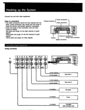
... cord connection Digital connection Connecting Audio Equipment Analog connection IN IN DEC OUT tOI DEC OUT IN • • CU PNI NO TUNER C O -APE : O TAPE 1 TA-E2000ESD • a. • • 11)!II 044 OW.• • • mom ego 00 OD 00 to line outputs to line inputs : Tape deck 1 to line...
... cord connection Digital connection Connecting Audio Equipment Analog connection IN IN DEC OUT tOI DEC OUT IN • • CU PNI NO TUNER C O -APE : O TAPE 1 TA-E2000ESD • a. • • 11)!II 044 OW.• • • mom ego 00 OD 00 to line outputs to line inputs : Tape deck 1 to line...
Primary User Manual
Page 8
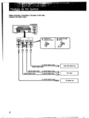
to optical digital output Optical digital cable Optical digital cable Optical digital cable to optical digital output to optical digital input to coaxial digital output Laser disc player, etc. DAT deck CD player, etc. 8 IGITA OPT ALl Remove the protection cover. 2 Insert the plug firmly. TA-E2000ESD 00 I RED 'UT COA AL 'PTICAL - 4.!1 Hooking the System Digital connection-Connecting a CD player or DAT deck equipped with digital output .. ..MM.
to optical digital output Optical digital cable Optical digital cable Optical digital cable to optical digital output to optical digital input to coaxial digital output Laser disc player, etc. DAT deck CD player, etc. 8 IGITA OPT ALl Remove the protection cover. 2 Insert the plug firmly. TA-E2000ESD 00 I RED 'UT COA AL 'PTICAL - 4.!1 Hooking the System Digital connection-Connecting a CD player or DAT deck equipped with digital output .. ..MM.

Primary User Manual
Page 9
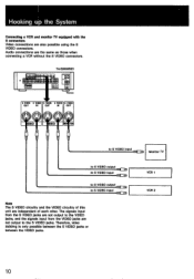
Connecting Video Equipment Connecting a video equipment which is not equipped with the S connectors TA-E2000ESD • •• e • 044 04/ • • WO1114•111 • • 00 Connecting a video camera recorder VCR 5 Vi10 to VIDEO 5 INPUT jacks on ...
Connecting Video Equipment Connecting a video equipment which is not equipped with the S connectors TA-E2000ESD • •• e • 044 04/ • • WO1114•111 • • 00 Connecting a video camera recorder VCR 5 Vi10 to VIDEO 5 INPUT jacks on ...
Primary User Manual
Page 10
TA-E2000ESD • • DD 0 •e • • S VIDEO S VIDEO S VIDEO S VIDEO S VIDEO OUT IN OUT IN OUT 0 IDEO O 0 O 0 0 0 a0 0 0 OO O IDEO MO TO 0 to S VIDEO Input ...
TA-E2000ESD • • DD 0 •e • • S VIDEO S VIDEO S VIDEO S VIDEO S VIDEO OUT IN OUT IN OUT 0 IDEO O 0 O 0 0 0 a0 0 0 OO O IDEO MO TO 0 to S VIDEO Input ...
Primary User Manual
Page 11
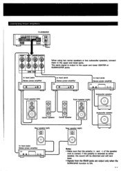
... lower jacks. The same signal is output to the upper and lower CENTER or SUBWOOFER jacks. Connecting Power Amplifiers . • • See ••• TA-E2000ESD • •41)•• I to input jacks Stereo power amplifier a st1D O O Front speaker (left) 0 8 O Center speaker Rear speaker (left) e O ..... 1.1•IIIIL to input jacks...
... lower jacks. The same signal is output to the upper and lower CENTER or SUBWOOFER jacks. Connecting Power Amplifiers . • • See ••• TA-E2000ESD • •41)•• I to input jacks Stereo power amplifier a st1D O O Front speaker (left) 0 8 O Center speaker Rear speaker (left) e O ..... 1.1•IIIIL to input jacks...
Primary User Manual
Page 12
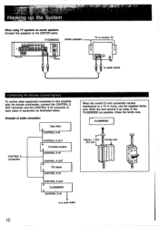
... deck CONTROL S IN CONTROL S connection CONTROL S OUT Turntable system CONTROL S IN CONTROL S OUT CD player CONTROL S IN CONTROL S OUT TA-E2000ESD CONTROL S IN to a wall outlet When the control S cord connection causes interference to a TV or tuner, use the supplied ferrite core. ...'".;r ;•'' 4-•" 'eLk SAY L Sfry ta-,:a;.; Close the ferrite core. Hooking up th-eSystem When using TV speakers as center speakers Connect the speakers to the TA-E2000ESD as possible. Wind the cord around it as illustrated below. TA-E2000ESD Approx. 1 €nch Ferrite core (2.5 cm)...
... deck CONTROL S IN CONTROL S connection CONTROL S OUT Turntable system CONTROL S IN CONTROL S OUT CD player CONTROL S IN CONTROL S OUT TA-E2000ESD CONTROL S IN to a wall outlet When the control S cord connection causes interference to a TV or tuner, use the supplied ferrite core. ...'".;r ;•'' 4-•" 'eLk SAY L Sfry ta-,:a;.; Close the ferrite core. Hooking up th-eSystem When using TV speakers as center speakers Connect the speakers to the TA-E2000ESD as possible. Wind the cord around it as illustrated below. TA-E2000ESD Approx. 1 €nch Ferrite core (2.5 cm)...

Primary User Manual
Page 13
Connecting Power Cords TTY! !L" CIO BEEIT=_ EEEE 00
Connecting Power Cords TTY! !L" CIO BEEIT=_ EEEE 00

Primary User Manual
Page 14
EE PRESET/USER button (page 44) Selects either the sound field preset at the factory or sound field preset by the user. 11 SOUNDFIELD PROGRAM buttons (page 29) Selects the desired sound field. gl MASTER VOLUME knob (page 26) Controls the audio level from the front and subwoofer. EISOURCE DIRECT button and indicator (page 31) Directly outputs the program source sound without passing through the parametric equalizer, dynamics and surround circuitry. Press the button again to check which parameter can be released. 14 El Remote control sensor El HEADPHONES jack Accepts the stereo ...
EE PRESET/USER button (page 44) Selects either the sound field preset at the factory or sound field preset by the user. 11 SOUNDFIELD PROGRAM buttons (page 29) Selects the desired sound field. gl MASTER VOLUME knob (page 26) Controls the audio level from the front and subwoofer. EISOURCE DIRECT button and indicator (page 31) Directly outputs the program source sound without passing through the parametric equalizer, dynamics and surround circuitry. Press the button again to check which parameter can be released. 14 El Remote control sensor El HEADPHONES jack Accepts the stereo ...

Primary User Manual
Page 15
The indicator lights when the displayed sub parameter can be set . El SUB PARAMETER button and indicator (pages 37 and 40) Selects the sub parameter to be set . The indicator lights when the main parameters can be set . of 0 0 0 CI 17 18 p MAIN PARAMETER button and indicators (pagea 34, 35, 36 and 41) Selects the pair of the parametric equalizer. p EQ BAND select button (page 41) Selects the desired band of the parametric equalizer. 17 EQ SLOPE select button (page 41) Selects the desired slope (O) of main parameters to be set . ID DIGITAL PROCESSING CONTROL knobs Set ...
The indicator lights when the displayed sub parameter can be set . El SUB PARAMETER button and indicator (pages 37 and 40) Selects the sub parameter to be set . The indicator lights when the main parameters can be set . of 0 0 0 CI 17 18 p MAIN PARAMETER button and indicators (pagea 34, 35, 36 and 41) Selects the pair of the parametric equalizer. p EQ BAND select button (page 41) Selects the desired band of the parametric equalizer. 17 EQ SLOPE select button (page 41) Selects the desired slope (O) of main parameters to be set . ID DIGITAL PROCESSING CONTROL knobs Set ...

Primary User Manual
Page 16
Turn the knob clockwise until just before OVER appears in the display. E CHARACTER button (page 45) Writes a title for recording while you are not output to the digital recording output jack (OPTICAL 2). Checks the former label on the sound field. NI BALANCE control knob Adjusts the balance between the left and right front speakers. wi ANALOG Input level knob (page 24) Adjusts the input level of Co ro S -Refer to be flat. El ENTER button (pages 43 and 45) Stores parameter settings or stores the title written. El EFFECT REC (record) button (page 31) Outputs the digitally-...
Turn the knob clockwise until just before OVER appears in the display. E CHARACTER button (page 45) Writes a title for recording while you are not output to the digital recording output jack (OPTICAL 2). Checks the former label on the sound field. NI BALANCE control knob Adjusts the balance between the left and right front speakers. wi ANALOG Input level knob (page 24) Adjusts the input level of Co ro S -Refer to be flat. El ENTER button (pages 43 and 45) Stores parameter settings or stores the title written. El EFFECT REC (record) button (page 31) Outputs the digitally-...

Primary User Manual
Page 17
DIGITAL : Input to the OPTICAL 2 IN jack DIGITAL is selected. : Input to make an effect recording. El Sound field name indication Indicates the sound field name selected. EE Equalizer curve indication Indicates the equalizer curve. El Character indication Indicates a sound field name, program source, operation mode or warning concerning incorrect operation. El EFFECT REC indication Lights when the EFFECT REC button is pressed to the COAXIAL IN jack is selected. 0 Sampling frequency indicator Indicates the sampling frequency of the digital signal input. (For example, in the ...
DIGITAL : Input to the OPTICAL 2 IN jack DIGITAL is selected. : Input to make an effect recording. El Sound field name indication Indicates the sound field name selected. EE Equalizer curve indication Indicates the equalizer curve. El Character indication Indicates a sound field name, program source, operation mode or warning concerning incorrect operation. El EFFECT REC indication Lights when the EFFECT REC button is pressed to the COAXIAL IN jack is selected. 0 Sampling frequency indicator Indicates the sampling frequency of the digital signal input. (For example, in the ...

Primary User Manual
Page 18
... to the right of this button to start recording.) You can "learn" various functions of the display to SONY STD (Sony standard), you can use infrared rays. El Mode selector (page 48) SONY STD: To control Sony equipment. El Input select buttons: Work in the same way as follows. e pages indicated in the following...
... to the right of this button to start recording.) You can "learn" various functions of the display to SONY STD (Sony standard), you can use infrared rays. El Mode selector (page 48) SONY STD: To control Sony equipment. El Input select buttons: Work in the same way as follows. e pages indicated in the following...
Primary User Manual
Page 19
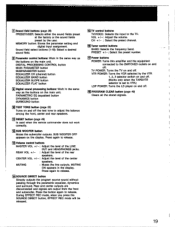
SUB WOOFER OFF appears on and off. Press again to release. ['Volume control buttons MASTER VOL +/-: Adjust the level of the center speakers. Press again to release. VOL +/-: Adjust the volume. CH +/- : Select the preset channel. TV POWER: Turns the TV on the display. MUTING : Mutes the line outputs. PRESET +/-: Select the preset number. ID Parameter control buttons: Work in the same way as the buttons on the main unit. CENTER VOL +/-: Adjust the level of the LINE OUT and HEADPHONES jacks. Press the button again to release. 14 SOURCE DIRECT button Directly ...
SUB WOOFER OFF appears on and off. Press again to release. ['Volume control buttons MASTER VOL +/-: Adjust the level of the center speakers. Press again to release. VOL +/-: Adjust the volume. CH +/- : Select the preset channel. TV POWER: Turns the TV on the display. MUTING : Mutes the line outputs. PRESET +/-: Select the preset number. ID Parameter control buttons: Work in the same way as the buttons on the main unit. CENTER VOL +/-: Adjust the level of the LINE OUT and HEADPHONES jacks. Press the button again to release. 14 SOURCE DIRECT button Directly ...

Primary User Manual
Page 20
Then select the Pro Logic mode according to the size of the rear speakers are used. Front (L) Center Front (R) Rear (L) qt1Rear (Ft) Set the PRO LOGIC MODE button to NORMAL or WIDE according to your speakers. In Dolby surround mode, adjustment of the volume of each speaker and adjustment of the delay time of the center speaker(s). The examples shown here only represent typical cases. adjust it beforehand to make the most of the room where the system is to find the speaker direction or location in which the most ideal speaker placement in total Two front speakers, ...
Then select the Pro Logic mode according to the size of the rear speakers are used. Front (L) Center Front (R) Rear (L) qt1Rear (Ft) Set the PRO LOGIC MODE button to NORMAL or WIDE according to your speakers. In Dolby surround mode, adjustment of the volume of each speaker and adjustment of the delay time of the center speaker(s). The examples shown here only represent typical cases. adjust it beforehand to make the most of the room where the system is to find the speaker direction or location in which the most ideal speaker placement in total Two front speakers, ...
