Service Manual
Page 1
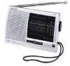
.... Please buy an AC power adaptor in the country where the radio is different depending on the country . FM STEREO/SW1-9/ MW/LW 12 BAND RECEIVER MICROFILM batteries Supplied accessory Short wave guide (1) Accessories not supplied AC power adaptor *AC-E3L, HG LW/MW/SW wide range antenna AN-1, AN-102 *The voltage of power supply is to change without notice...
.... Please buy an AC power adaptor in the country where the radio is different depending on the country . FM STEREO/SW1-9/ MW/LW 12 BAND RECEIVER MICROFILM batteries Supplied accessory Short wave guide (1) Accessories not supplied AC power adaptor *AC-E3L, HG LW/MW/SW wide range antenna AN-1, AN-102 *The voltage of power supply is to change without notice...
Service Manual
Page 2
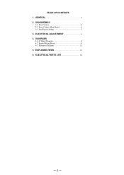
ELECTRICAL ADJUSTMENT 6 4. Schematic Diagram 11 5. TABLE OF CONTENTS 1. EXPLODED VIEWS 13 6. Front Cabinet, Main Board 4 2-3. Rear Cabinet 4 2-2. Dial Pointer Setting 5 3. DIAGRAMS 4-1. Printed Wiring Board 9 4-3. DISASSEMBLY 2-1. IC Block Diagram 8 4-2. GENERAL 3 2. ELECTRICAL PARTS LIST 14 - 2 -
ELECTRICAL ADJUSTMENT 6 4. Schematic Diagram 11 5. TABLE OF CONTENTS 1. EXPLODED VIEWS 13 6. Front Cabinet, Main Board 4 2-3. Rear Cabinet 4 2-2. Dial Pointer Setting 5 3. DIAGRAMS 4-1. Printed Wiring Board 9 4-3. DISASSEMBLY 2-1. IC Block Diagram 8 4-2. GENERAL 3 2. ELECTRICAL PARTS LIST 14 - 2 -
Service Manual
Page 3
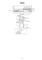
BAND select switch SECTION 1 GENERAL BAND indicator POWER switch - 3 -
BAND select switch SECTION 1 GENERAL BAND indicator POWER switch - 3 -

Service Manual
Page 4
SECTION 2 DISASSEMBLY Note : Follow the disassembly procedure in the numerical order given. 2-1. REAR CABINET 3 Three screws (P2.6 × 16) 2 Stand 4 Two screws (P2.6 × 16) Claw 5 Cabinet (rear) (The cabinet is locked by the claws) 2-2. FRONT CABINET, MAIN BOARD 1 Lid, battery case MAIN board 5 S2 MAIN board 1 Screw 3 Screw (P2 × 8) (BTP2.6 × 8) 8 MAIN BOARD 4 Terminal, battery Claw D2 6 Main chassis Claw 2 Front Cabinet - 4 - MAIN board 7 Terminal (Minus), battery Main chassis
SECTION 2 DISASSEMBLY Note : Follow the disassembly procedure in the numerical order given. 2-1. REAR CABINET 3 Three screws (P2.6 × 16) 2 Stand 4 Two screws (P2.6 × 16) Claw 5 Cabinet (rear) (The cabinet is locked by the claws) 2-2. FRONT CABINET, MAIN BOARD 1 Lid, battery case MAIN board 5 S2 MAIN board 1 Screw 3 Screw (P2 × 8) (BTP2.6 × 8) 8 MAIN BOARD 4 Terminal, battery Claw D2 6 Main chassis Claw 2 Front Cabinet - 4 - MAIN board 7 Terminal (Minus), battery Main chassis
Service Manual
Page 5
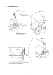
A 5 Scale, dial 4 Belt (Tun) 1 Turn the variable capacitor fully counterclockwise. Apply suitable locking compound to C portion. - 5 - 6 Pointer Knob (Tun) A C Center of the scratched lines on the center of B scratched line 7 First, turn the tuning shaft fully in the arrow A direction. DIAL POINTER SETTING 3 Screw (1.7 × 3) Flat (+) special 2 Mach the hole with setting the variable capacitor gear gap in the arrow B direction and set it on the dial scale plate. 2-3. Move only the dial pointer in the arrow A direction.
A 5 Scale, dial 4 Belt (Tun) 1 Turn the variable capacitor fully counterclockwise. Apply suitable locking compound to C portion. - 5 - 6 Pointer Knob (Tun) A C Center of the scratched lines on the center of B scratched line 7 First, turn the tuning shaft fully in the arrow A direction. DIAL POINTER SETTING 3 Screw (1.7 × 3) Flat (+) special 2 Mach the hole with setting the variable capacitor gear gap in the arrow B direction and set it on the dial scale plate. 2-3. Move only the dial pointer in the arrow A direction.
Service Manual
Page 6
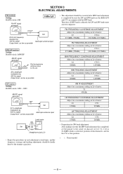
... 400 Hz signal Output level : as low as possible Set telescopic antenna input Level meter 32Ω Set Headphones jack (J1) • Repeat the procedures in each adjustment several times, and the frequency coverage and tracking adjustments should be finally done by 400 Hz signal Output level : as low as possible • This adjustment should be executed after MW band adjustment is completed because the LW and SW bands use the...
... 400 Hz signal Output level : as low as possible Set telescopic antenna input Level meter 32Ω Set Headphones jack (J1) • Repeat the procedures in each adjustment several times, and the frequency coverage and tracking adjustments should be finally done by 400 Hz signal Output level : as low as possible • This adjustment should be executed after MW band adjustment is completed because the LW and SW bands use the...
Service Manual
Page 7
... CT1-4 RV1 VCO FM Frequency Coverage Adjustment Adjustment - 7 - - 8 - If not received, readjust, then repeat 1. ( ) : Tourist model MAIN BOARD (conductor side) D2 TUNE [VCO Adjustment] Procedure : FM RF signal generator Center frequency :98 MHz Modulation : no modulation Output level : 0.1 V (100dB) Set telescopic antenna input 1. Connect frequency counter to Headphones jack (J1). 2. L6 FM Tracking CT1-3 Adjustment CT1-1 MW Tracking Adjustment CT2 LW Tracking Adjustment PLL LPF1 PILOT DET LPF2 PILOT...
... CT1-4 RV1 VCO FM Frequency Coverage Adjustment Adjustment - 7 - - 8 - If not received, readjust, then repeat 1. ( ) : Tourist model MAIN BOARD (conductor side) D2 TUNE [VCO Adjustment] Procedure : FM RF signal generator Center frequency :98 MHz Modulation : no modulation Output level : 0.1 V (100dB) Set telescopic antenna input 1. Connect frequency counter to Headphones jack (J1). 2. L6 FM Tracking CT1-3 Adjustment CT1-1 MW Tracking Adjustment CT2 LW Tracking Adjustment PLL LPF1 PILOT DET LPF2 PILOT...
Service Manual
Page 8
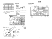
...BATTERY SIZE "AA" (ICE DESIGNATION R6) 2PCS, 3V - 10 - No. ICF-SW11 4-2. PRINTED WIRING BOARD 1 2 3 4 5 6 7 8 9 10 11 MAIN BOARD A D2 TUNE L29 BAR ANTENNA L27 L1 L2 MW LW B C E C 12 BE B CF1 C BE CF2 16 15 T1 C52 L3 L28 C 2 1 L26 20 C36 10 EXCEPT JE MODEL L6 C39 25 R16 5 EXCEPT JE MODEL...L17 L20 F L11 L13 L15 L18 L19 L22 L23 L25 S2 POWER 2 OFF SI BAND FW MW LW SW9 SW8 SW7 SW6 SW5 SW4 SW3 SW2 SW1 G ON 16 12 13 ANT1 TELESCOPIC ANTENNA RV2 VOLUME C60 J1 SP901 (SPEAKER) J2 DC IN 3V 15 (15) • Semiconductor Location Ref...
...BATTERY SIZE "AA" (ICE DESIGNATION R6) 2PCS, 3V - 10 - No. ICF-SW11 4-2. PRINTED WIRING BOARD 1 2 3 4 5 6 7 8 9 10 11 MAIN BOARD A D2 TUNE L29 BAR ANTENNA L27 L1 L2 MW LW B C E C 12 BE B CF1 C BE CF2 16 15 T1 C52 L3 L28 C 2 1 L26 20 C36 10 EXCEPT JE MODEL L6 C39 25 R16 5 EXCEPT JE MODEL...L17 L20 F L11 L13 L15 L18 L19 L22 L23 L25 S2 POWER 2 OFF SI BAND FW MW LW SW9 SW8 SW7 SW6 SW5 SW4 SW3 SW2 SW1 G ON 16 12 13 ANT1 TELESCOPIC ANTENNA RV2 VOLUME C60 J1 SP901 (SPEAKER) J2 DC IN 3V 15 (15) • Semiconductor Location Ref...
Service Manual
Page 9
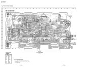
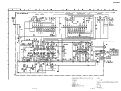
.... L2, CT2 LW TRACKING L1, CT1-1 MW TRACKING ICF-SW11 L5, CT3 LW FREQUENCY COVERAGE L4, CT1-2 MW FREQUENCY COVERAGE L6, CT1-3 FM TRACKING L17-L25 SW FREQUENCY COVERAGE L7,CT1-4 FM FREQUENCY COVERAGE EXCEPT JE MODEL (JE) 27µH(EXCEPT JE) JE MODEL EXCEPT JE MODEL - 11 - SCHEMATIC DIAGRAM • Refer to normal production tolerances. • Signal path. F : FM •...
.... L2, CT2 LW TRACKING L1, CT1-1 MW TRACKING ICF-SW11 L5, CT3 LW FREQUENCY COVERAGE L4, CT1-2 MW FREQUENCY COVERAGE L6, CT1-3 FM TRACKING L17-L25 SW FREQUENCY COVERAGE L7,CT1-4 FM FREQUENCY COVERAGE EXCEPT JE MODEL (JE) 27µH(EXCEPT JE) JE MODEL EXCEPT JE MODEL - 11 - SCHEMATIC DIAGRAM • Refer to normal production tolerances. • Signal path. F : FM •...
Service Manual
Page 10
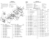
...01 BASE(BAND) 8-719-812-41 DIODE GL3PR8 (TUNE) 1-501-222-81 ANTENNA, TELESCOPIC (FM) 1-544-517-11 SPEAKER 16 3-380-909-01 KNOB(TUN) #1 7-685-105-19 TPG +P 2 × 8, TYPE 2, NON-SLIT 17 3-380-918-31 STAND #2 7-685-138-19 SCREW +P...indicating parts by reference number, please include the board name. • SEMICONDUCTORS In each case, u: µ, for example: uA...: µA... , uPA... , µPA... , uPB... , µPB... , uPC... , µPC... , uPD..., µPD... • Abbreviation CND : Canadian model IT : Italian model EA : Saudi Arabia model CH : Chinese model JE : Tourist model...
...01 BASE(BAND) 8-719-812-41 DIODE GL3PR8 (TUNE) 1-501-222-81 ANTENNA, TELESCOPIC (FM) 1-544-517-11 SPEAKER 16 3-380-909-01 KNOB(TUN) #1 7-685-105-19 TPG +P 2 × 8, TYPE 2, NON-SLIT 17 3-380-918-31 STAND #2 7-685-138-19 SCREW +P...indicating parts by reference number, please include the board name. • SEMICONDUCTORS In each case, u: µ, for example: uA...: µA... , uPA... , µPA... , uPB... , µPB... , uPC... , µPC... , uPD..., µPD... • Abbreviation CND : Canadian model IT : Italian model EA : Saudi Arabia model CH : Chinese model JE : Tourist model...
Service Manual
Page 12
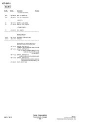
...-22 MANUAL, INSTRUCTION (DANISH,FINNISH,POLISH,RUSSIAN)(AEP) 3-867-546-32 MANUAL, INSTRUCTION (ENGLISH,FRENCH,GERMAN,SPANISH, PORTUGUESE,KOREAN,ARABIC)(E,EA) 3-912-863-05 GUIDE, SHORT WAVE Description Remarks 9-927-176-11 Sony Corporation Personal Audio Company - 16 - 99I1674-1 Printed in Japan ©1999.9 Published by General Engineering Dept. No. Part No. No. Description < VARIABLE RESISTOR > Remarks Ref. ICF-SW11 MAIN Ref. Part...
...-22 MANUAL, INSTRUCTION (DANISH,FINNISH,POLISH,RUSSIAN)(AEP) 3-867-546-32 MANUAL, INSTRUCTION (ENGLISH,FRENCH,GERMAN,SPANISH, PORTUGUESE,KOREAN,ARABIC)(E,EA) 3-912-863-05 GUIDE, SHORT WAVE Description Remarks 9-927-176-11 Sony Corporation Personal Audio Company - 16 - 99I1674-1 Printed in Japan ©1999.9 Published by General Engineering Dept. No. Part No. No. Description < VARIABLE RESISTOR > Remarks Ref. ICF-SW11 MAIN Ref. Part...


