Instructions
Page 1
3-300-474-11(1) FLOOR STAND Instructions US Mode d'emploi FR Instrucciones ES SU-FL71M © 2008 Sony Corporation
3-300-474-11(1) FLOOR STAND Instructions US Mode d'emploi FR Instrucciones ES SU-FL71M © 2008 Sony Corporation
Instructions
Page 2
... pinch the AC power cord or the connecting cable. Moving excessive weight may fall . Keep this manual available for purchasing this product should only be installed by Sony are designed with safety in one direction. If you fail to install the stand on the stand or move the stand with the TV ... refer to their operating instructions, or the supplied leaflet to attach the stand securely by incorrect installation or handling. Be sure to verify that it from toppling over . Certain models may be pinched when you install the TV on a solid and level floor. This may result in ...
... pinch the AC power cord or the connecting cable. Moving excessive weight may fall . Keep this manual available for purchasing this product should only be installed by Sony are designed with safety in one direction. If you fail to install the stand on the stand or move the stand with the TV ... refer to their operating instructions, or the supplied leaflet to attach the stand securely by incorrect installation or handling. Be sure to verify that it from toppling over . Certain models may be pinched when you install the TV on a solid and level floor. This may result in ...
Instructions
Page 3
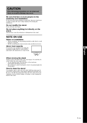
... or deformation of the stand. NOTE ON USE Notes on installation • When assembling, lay the packing materials on the floor to avoid damage to dry the area afterwards with a dry soft cloth. Be sure that two or more people do the assembly and installation. The base parts of the stand. 3 (US) How to clean the stand Occasionally wipe it may...
... or deformation of the stand. NOTE ON USE Notes on installation • When assembling, lay the packing materials on the floor to avoid damage to dry the area afterwards with a dry soft cloth. Be sure that two or more people do the assembly and installation. The base parts of the stand. 3 (US) How to clean the stand Occasionally wipe it may...
Instructions
Page 4
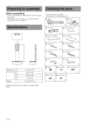
... to change without notice. ×1 ×1 G Bracket 32" L H Bracket 32" R ×1 ×1 I Bracket L J Bracket R K Arm ×1 ×1 L Shelf M Hook ×1 N Lock Screw ×1 O Screw (M6 × 16) ×2 ×2 ×8 P Screw (M5 × 12) Q Screw (M4 × 8) ×8 ×8 4 (US) A Pillar B Base Specifications C Front Cover ×1 ×1 D Rear Cover Top ×1 ×1 E Rear Cover Bottom F Base Cover d a b c Dimensions: a mm (inches) b c d Weight: 1,022 (40 1/4) 600 (23 5/8) 400 (15...
... to change without notice. ×1 ×1 G Bracket 32" L H Bracket 32" R ×1 ×1 I Bracket L J Bracket R K Arm ×1 ×1 L Shelf M Hook ×1 N Lock Screw ×1 O Screw (M6 × 16) ×2 ×2 ×8 P Screw (M5 × 12) Q Screw (M4 × 8) ×8 ×8 4 (US) A Pillar B Base Specifications C Front Cover ×1 ×1 D Rear Cover Top ×1 ×1 E Rear Cover Bottom F Base Cover d a b c Dimensions: a mm (inches) b c d Weight: 1,022 (40 1/4) 600 (23 5/8) 400 (15...
Instructions
Page 5
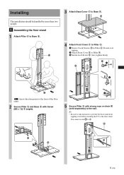
...) Installing The installation should be handled by more than two people. 1 Assembling the floor stand 1 Attach Pillar A to Pillar A. N 1 C 2 B Arrow direction points to the front of the floor stand. 2 Secure Pillar A and Base B with Screw (M5 × 12) P (eight). 3 5 Secure Pillar A with strong rope or chain (sold separately) to the wall. ~ • Be sure to take measures to prevent the floor stand from...
...) Installing The installation should be handled by more than two people. 1 Assembling the floor stand 1 Attach Pillar A to Pillar A. N 1 C 2 B Arrow direction points to the front of the floor stand. 2 Secure Pillar A and Base B with Screw (M5 × 12) P (eight). 3 5 Secure Pillar A with strong rope or chain (sold separately) to the wall. ~ • Be sure to take measures to prevent the floor stand from...
Instructions
Page 6
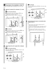
... the rear of the TV. 2 Secure them with Screw O (M6 × 16) (two) to 32" bracket GH or Bracket IJ. G O H 3 Connecting the AC power cord and the other cables only. • The cables connecting position differs depending on the TV model. I O J B For 32 inch: Adjust Hook M with Screw (M6 × 16) O (four). 2 Preparing for the installation of the TV The parts installation...
... the rear of the TV. 2 Secure them with Screw O (M6 × 16) (two) to 32" bracket GH or Bracket IJ. G O H 3 Connecting the AC power cord and the other cables only. • The cables connecting position differs depending on the TV model. I O J B For 32 inch: Adjust Hook M with Screw (M6 × 16) O (four). 2 Preparing for the installation of the TV The parts installation...
Instructions
Page 7
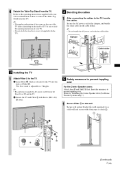
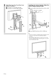
... toppling over For the Center Speaker users: Attach Arm K and Shelf L first, then take measures to prevent toppling over. (Refer to "Installing the Center Speaker table (For Home Theatre Systems only)".) 1 Secure Pillar A to remove the Table-Top Stand from the TV. Refer to the operating instructions supplied with your TV. • Do not attach the stand rear covers (if supplied with...
... toppling over For the Center Speaker users: Attach Arm K and Shelf L first, then take measures to prevent toppling over. (Refer to "Installing the Center Speaker table (For Home Theatre Systems only)".) 1 Secure Pillar A to remove the Table-Top Stand from the TV. Refer to the operating instructions supplied with your TV. • Do not attach the stand rear covers (if supplied with...
Instructions
Page 8
... E to Pillar A. 1 Attach Rear Cover Top D to Pillar A. 2 Attach Rear Cover Bottom E to Pillar A with Screw (M4 × 8) Q (four). ~ • Do not use an electric screwdriver when securing the acrylic board since it may break if the tightening strength is excessive. • The maximum weight capacity is adjustable to 4 heights. 1 D 2 E K 1Q 2 Secure Shelf L with Screw (M4 × 8) Q (four...
... E to Pillar A. 1 Attach Rear Cover Top D to Pillar A. 2 Attach Rear Cover Bottom E to Pillar A with Screw (M4 × 8) Q (four). ~ • Do not use an electric screwdriver when securing the acrylic board since it may break if the tightening strength is excessive. • The maximum weight capacity is adjustable to 4 heights. 1 D 2 E K 1Q 2 Secure Shelf L with Screw (M4 × 8) Q (four...

Instructions
Page 28
http://www.sony.net/ Printed in China
http://www.sony.net/ Printed in China


