Limited Warranty (ES Products)
Page 1
...to state. This warranty is valid only in the form of a bill of sale or receipted invoice which vary from the Product. PARTS: In addition, Sony will repair or replace the Product, at its original packaging or packaging affording an equal degree of protection, to any authorized...an implied warranty lasts does not apply to you . 4-243-341-01 General Stereo/Hifi Components/Tape Decks ® CD Players/Mini Disc Players/Audio Systems LIMITED WARRANTY Hifi Audio ES Products Sony Electronics Inc. ("Sony") warrants this Product is within 90 days of the date of sale, the ...
...to state. This warranty is valid only in the form of a bill of sale or receipted invoice which vary from the Product. PARTS: In addition, Sony will repair or replace the Product, at its original packaging or packaging affording an equal degree of protection, to any authorized...an implied warranty lasts does not apply to you . 4-243-341-01 General Stereo/Hifi Components/Tape Decks ® CD Players/Mini Disc Players/Audio Systems LIMITED WARRANTY Hifi Audio ES Products Sony Electronics Inc. ("Sony") warrants this Product is within 90 days of the date of sale, the ...
Technical Background
Page 2
...and Specifications Page 3 Page 4 Page 16 Page 23 Page 26 Page 28 Page 35 Page 37 ES Receivers v1.0 Page 2 You can listen to this expertise, Sony's ES Series receivers have been praised by equipment reviewers, cherished by home theater enthusiasts and scrutinized by an entire industry. ... digital transmission from a Super Audio CD or DVD player. Digital Home Theater and Sony ES S-Master Pro amplifier with 32-bit processing and a new generation of the Sony ES Series, the Elevated Standard in part to upgraded surround sound formats, including Dolby Digital® EX 6.1 channel sound, ...
...and Specifications Page 3 Page 4 Page 16 Page 23 Page 26 Page 28 Page 35 Page 37 ES Receivers v1.0 Page 2 You can listen to this expertise, Sony's ES Series receivers have been praised by equipment reviewers, cherished by home theater enthusiasts and scrutinized by an entire industry. ... digital transmission from a Super Audio CD or DVD player. Digital Home Theater and Sony ES S-Master Pro amplifier with 32-bit processing and a new generation of the Sony ES Series, the Elevated Standard in part to upgraded surround sound formats, including Dolby Digital® EX 6.1 channel sound, ...
Technical Background
Page 11
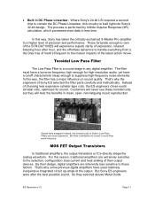
... toroidal coils, but they selected deluxe Metal Oxide ES Receivers v1.0 Page 11 Those fortunate enough to the meteor impacts of Sony's Low Pass Filters are more data in DC Phase ...In this reason, traditional amplifiers are inherently less sensitive to a higher level of Sony ES selected the filter parts carefully and methodically. Instead of their contribution to suppress high-frequency noise elements. MOS...to handle everything from a the Dies Irae of Verdi's Requiem to own of the STR-DA7100ES will hear the benefits in black, the toroidal coils of the latest action ...
... toroidal coils, but they selected deluxe Metal Oxide ES Receivers v1.0 Page 11 Those fortunate enough to the meteor impacts of Sony's Low Pass Filters are more data in DC Phase ...In this reason, traditional amplifiers are inherently less sensitive to a higher level of Sony ES selected the filter parts carefully and methodically. Instead of their contribution to suppress high-frequency noise elements. MOS...to handle everything from a the Dies Irae of Verdi's Requiem to own of the STR-DA7100ES will hear the benefits in black, the toroidal coils of the latest action ...
Technical Background
Page 14
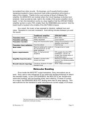
... heat radiation Heat sinks Space requirements Amplifier board location Overall chassis topology Traditional amplifier Major design concern Widely separated Away from heat-sensitive parts From the bottom Massive radiating fins made of die cast aluminum (on the amplifier circuit board From the top A single sheet of...you 'll usually find the output transistors bonded to the cool running of Sony's S-Master Pro amplifier, the MOS FETs are at the back or sides of the chassis. ES Receivers v1.0 Page 14 In the STR-DA9000ES, the MOS FETs use "double wire molecular bonding" with two bonding wires...
... heat radiation Heat sinks Space requirements Amplifier board location Overall chassis topology Traditional amplifier Major design concern Widely separated Away from heat-sensitive parts From the bottom Massive radiating fins made of die cast aluminum (on the amplifier circuit board From the top A single sheet of...you 'll usually find the output transistors bonded to the cool running of Sony's S-Master Pro amplifier, the MOS FETs are at the back or sides of the chassis. ES Receivers v1.0 Page 14 In the STR-DA9000ES, the MOS FETs use "double wire molecular bonding" with two bonding wires...
Technical Background
Page 36
... • Infrared repeater ports (STR-DA2100ES and higher). Real estate on and listen. Conclusion Beginning with third-party room automation systems, these receivers also accept optical digital audio, in 1982, the engineers of Sony's ES Series have been extending ...STR-DA2100ES and higher). Recreates the effect of a full array of modern A/V receivers is hidden away, ES Series receivers offer one infrared repeater input and two outputs. To communicate with the PCM-701ES digital processor in addition to Left/Right analog audio. • Assignable digital input (all models). As part...
... • Infrared repeater ports (STR-DA2100ES and higher). Real estate on and listen. Conclusion Beginning with third-party room automation systems, these receivers also accept optical digital audio, in 1982, the engineers of Sony's ES Series have been extending ...STR-DA2100ES and higher). Recreates the effect of a full array of modern A/V receivers is hidden away, ES Series receivers offer one infrared repeater input and two outputs. To communicate with the PCM-701ES digital processor in addition to Left/Right analog audio. • Assignable digital input (all models). As part...
Technical Background
Page 38
... 1394 connector may not be compatible with some brands or models. All other . i.LINK is prohibited. ES Receivers v1.0 Page 38 Reproduction in whole or in part without notice. Features and specifciations are property of Sony used only to designate that comes with each other trademarks are subject to the documentation that product...
... 1394 connector may not be compatible with some brands or models. All other . i.LINK is prohibited. ES Receivers v1.0 Page 38 Reproduction in whole or in part without notice. Features and specifciations are property of Sony used only to designate that comes with each other trademarks are subject to the documentation that product...

Operating Instructions
Page 2
... - If you have any interference received, including interference that interference will not occur in particular, specifies that to operate this product, you may cause harmful interference to the presence of Conformity Trade name: SONY Model No.: STR-DA9000ES Responsible Party: Sony Electronics Inc. The Number below is... candles on the apparatus. Don't throw away batteries with Part 15 of the FCC Rules. ENERGY STAR® is for a Class B digital device, pursuant to radio or television reception, which the receiver is no guarantee that may not cause harmful interference, and...
... - If you have any interference received, including interference that interference will not occur in particular, specifies that to operate this product, you may cause harmful interference to the presence of Conformity Trade name: SONY Model No.: STR-DA9000ES Responsible Party: Sony Electronics Inc. The Number below is... candles on the apparatus. Don't throw away batteries with Part 15 of the FCC Rules. ENERGY STAR® is for a Class B digital device, pursuant to radio or television reception, which the receiver is no guarantee that may not cause harmful interference, and...

Operating Instructions
Page 30
function. U NEO:6: Lights up when the receiver applies Pro Logic processing to 2 channel signals in order to tune in all parts of the LFE channel signal is actually being played back contains the LFE (Low Frequency Effect) channel. PRO LOGIC (II): Lights up... the sound of the input signal the bar indication will fluctuate (and may turn off) during playback. 30GB P H.A.T.S.: Lights up when using the receiver to output the center and surround channel signals. O Tuner indicators: Lights up when the connected i.LINK component is compatible with H.A.T.S. See pages 26-...
function. U NEO:6: Lights up when the receiver applies Pro Logic processing to 2 channel signals in order to tune in all parts of the LFE channel signal is actually being played back contains the LFE (Low Frequency Effect) channel. PRO LOGIC (II): Lights up... the sound of the input signal the bar indication will fluctuate (and may turn off) during playback. 30GB P H.A.T.S.: Lights up when using the receiver to output the center and surround channel signals. O Tuner indicators: Lights up when the connected i.LINK component is compatible with H.A.T.S. See pages 26-...

Operating Instructions
Page 62
... standby mode) 1 W AC outlets 1 switched, 120 W/1A MAX Dimensions 430 × 238 × 480 mm including projecting parts and controls Mass (Approx.) 28.5 kg Supplied accessories FM wire antenna (1) AM loop antenna (1) Remote commander RM-TP2 (1) RMB-TP2 (1 for RM-TP2) Remote commander RM-US106 (1) ...62GB R6 (size-AA) batteries (2) For details on the area code of DTLA (Revision 1.2). After tuning in any AM station, turn off the receiver. While...
... standby mode) 1 W AC outlets 1 switched, 120 W/1A MAX Dimensions 430 × 238 × 480 mm including projecting parts and controls Mass (Approx.) 28.5 kg Supplied accessories FM wire antenna (1) AM loop antenna (1) Remote commander RM-TP2 (1) RMB-TP2 (1 for RM-TP2) Remote commander RM-US106 (1) ...62GB R6 (size-AA) batteries (2) For details on the area code of DTLA (Revision 1.2). After tuning in any AM station, turn off the receiver. While...

Operating Instructions
Page 64
List of button locations and reference pages How to use this page Use this page to find the location of buttons and other parts of button/part Reference page Main unit ALPHABETICAL ORDER A.F.D. 7 (31, 32, 34) BASS eh (40) DECODE PRIORITY ws (41) Digital Cinema Sound indicator 5 DIRECT wd (34) ...DIRECT indicator 2 DISPLAY wa (28) Display 3 (28) FM/AM qh (26, 27) Input indicators qf INPUT MODE qs (37) INPUT SELECTOR qa (25, 37, ...
List of button locations and reference pages How to use this page Use this page to find the location of buttons and other parts of button/part Reference page Main unit ALPHABETICAL ORDER A.F.D. 7 (31, 32, 34) BASS eh (40) DECODE PRIORITY ws (41) Digital Cinema Sound indicator 5 DIRECT wd (34) ...DIRECT indicator 2 DISPLAY wa (28) Display 3 (28) FM/AM qh (26, 27) Input indicators qf INPUT MODE qs (37) INPUT SELECTOR qa (25, 37, ...
Service Manual
Page 3
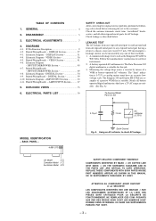
.... ON THE SCHEMATIC DIAGRAMS AND IN THE PARTS LIST ARE CRITICAL TO SAFE OPERATION. REPLACE THESE COMPONENTS WITH SONY PARTS WHOSE PART NUMBERS APPEAR AS SHOWN IN THIS MANUAL OR IN SUPPLEMENTS PUBLISHED BY SONY. POSANTS QUE PAR DES PIÈCES SONY DONT LES NUMÉROS SONT DONNÉ...;S DANS CE MANUEL OU DANS LES SUPPLÉMENTS PUBLIÉS PAR SONY. - 3 - DISASSEMBLY 5 3. Printed Wiring Boards - ELECTRICAL PARTS LIST 79 SAFETY CHECK-OUT After correcting the original service problem, perform the following safety check before releasing the set ...
.... ON THE SCHEMATIC DIAGRAMS AND IN THE PARTS LIST ARE CRITICAL TO SAFE OPERATION. REPLACE THESE COMPONENTS WITH SONY PARTS WHOSE PART NUMBERS APPEAR AS SHOWN IN THIS MANUAL OR IN SUPPLEMENTS PUBLISHED BY SONY. POSANTS QUE PAR DES PIÈCES SONY DONT LES NUMÉROS SONT DONNÉ...;S DANS CE MANUEL OU DANS LES SUPPLÉMENTS PUBLIÉS PAR SONY. - 3 - DISASSEMBLY 5 3. Printed Wiring Boards - ELECTRICAL PARTS LIST 79 SAFETY CHECK-OUT After correcting the original service problem, perform the following safety check before releasing the set ...

Service Manual
Page 8
... 1 R665 + R016 2 - R715 R765 3 [AMP BOARD] (COMPONENT SIDE) FRONT Lch FRONT Rch CENTER REAR Lch REAR Rch Connecting point R615 R665 R016 R715 R765 Adjustment part RV601 RV651 RV001 RV701 RV751 Reading on (POWER ON). 2. After replacing the power transistors, DC BIAS CURRENT adjustments should be perfomed. DC BIAS CURRENT adjustments...
... 1 R665 + R016 2 - R715 R765 3 [AMP BOARD] (COMPONENT SIDE) FRONT Lch FRONT Rch CENTER REAR Lch REAR Rch Connecting point R615 R665 R016 R715 R765 Adjustment part RV601 RV651 RV001 RV701 RV751 Reading on (POWER ON). 2. After replacing the power transistors, DC BIAS CURRENT adjustments should be perfomed. DC BIAS CURRENT adjustments...

Service Manual
Page 42
... 3-704-366-01 SCREW (CASE) (M3X8) 4-982-090-01 CASE (414538E) 4-985-642-01 CUSHION #1 4 #1 5 not supplied #2 Remark Ref. No. 4 5 Part No. sont critiquens pour la sécurité. Ne les remplacer que par une pièce portant le neméro spécifi...FOOT (F50180S) 4-970-124-01 CUSHION (F50180S) Remark - 75 - Replace only with mark ! No. 1 *2 3 Part No. Some delay should be anticipated when ordering these items. • The mechanical parts with no reference number in the exploded views are not supplied. • Hardware (# mark) list and accessories and packing...
... 3-704-366-01 SCREW (CASE) (M3X8) 4-982-090-01 CASE (414538E) 4-985-642-01 CUSHION #1 4 #1 5 not supplied #2 Remark Ref. No. 4 5 Part No. sont critiquens pour la sécurité. Ne les remplacer que par une pièce portant le neméro spécifi...FOOT (F50180S) 4-970-124-01 CUSHION (F50180S) Remark - 75 - Replace only with mark ! No. 1 *2 3 Part No. Some delay should be anticipated when ordering these items. • The mechanical parts with no reference number in the exploded views are not supplied. • Hardware (# mark) list and accessories and packing...

Service Manual
Page 43
...) 4-991-378-71 PANEL, FRONT (Australian) 4-942-568-01 EMBLEM (NO.5), SONY X-4948-618-1 LID (FRONT) ASSY 3-974-992-01 SLIDER (L), DOOR 55 #3 89 88 Remark Ref. No. 51 51 52 53 54 Part No. No. * 76 * 76 77 78 79 Part No. (2) FRONT PANEL SECTION 73 65 66 72 70 #1 67 M101...
...) 4-991-378-71 PANEL, FRONT (Australian) 4-942-568-01 EMBLEM (NO.5), SONY X-4948-618-1 LID (FRONT) ASSY 3-974-992-01 SLIDER (L), DOOR 55 #3 89 88 Remark Ref. No. 51 51 52 53 54 Part No. No. * 76 * 76 77 78 79 Part No. (2) FRONT PANEL SECTION 73 65 66 72 70 #1 67 M101...

Service Manual
Page 44
Description Remark 4-991-373-21 PANEL (STR), BACK (Australian) A-4398-801-A S VIDEO BOARD, COMPLETE A-4398-799-A VIDEO BOARD, COMPLETE (US, Canadian) A-4398-800-A VIDEO BOARD, COMPLETE (Australian) A-4398-802-A AUDIO BOARD, ... not supplied #1 161 #1 160 #1 152 Australian CNS901 #1 #1 151 164 chassis section The components identified by mark ! Replace only with mark ! Ref. or dotted line with part number specified. CNS901 1-251-416-11 OUTLET, A.C. (Australian) ! T901 ! T901 1-431-389-11 TRANSFORMER, POWER (Australian) 1-431-391-11 TRANSFORMER, POWER (US) 1-431-...
Description Remark 4-991-373-21 PANEL (STR), BACK (Australian) A-4398-801-A S VIDEO BOARD, COMPLETE A-4398-799-A VIDEO BOARD, COMPLETE (US, Canadian) A-4398-800-A VIDEO BOARD, COMPLETE (Australian) A-4398-802-A AUDIO BOARD, ... not supplied #1 161 #1 160 #1 152 Australian CNS901 #1 #1 151 164 chassis section The components identified by mark ! Replace only with mark ! Ref. or dotted line with part number specified. CNS901 1-251-416-11 OUTLET, A.C. (Australian) ! T901 ! T901 1-431-389-11 TRANSFORMER, POWER (Australian) 1-431-391-11 TRANSFORMER, POWER (US) 1-431-...

Service Manual
Page 45
No. * 205 206 * 207 * 208 Part No. Description 1-666-310-11 TUNER BOARD 1-773-001-11 WIRE (FLAT TYPE) (15 CORE) A-4398-782-A INPUT BOARD, COMPLETE A-4398-806-A DIGITAL BOARD, COMPLETE ...-01 CUSHION (F50180S) 4-970-123-01 FOOT (F50180S) 3-905-609-01 SCREW (TRANSISTOR) A-4398-783-A AMP BOARD, COMPLETE Remark Ref. No. 201 202 203 * 204 Part No.
No. * 205 206 * 207 * 208 Part No. Description 1-666-310-11 TUNER BOARD 1-773-001-11 WIRE (FLAT TYPE) (15 CORE) A-4398-782-A INPUT BOARD, COMPLETE A-4398-806-A DIGITAL BOARD, COMPLETE ...-01 CUSHION (F50180S) 4-970-123-01 FOOT (F50180S) 3-905-609-01 SCREW (TRANSISTOR) A-4398-783-A AMP BOARD, COMPLETE Remark Ref. No. 201 202 203 * 204 Part No.

Service Manual
Page 46
.... . are critical for routine service. Ne les remplacer que par une pièce portant le neméro spécifié. No. * * Part No. No. Description < FUSE > Remark ! R901 1-202-725-00 SOLID R902 R903 R904 1-249-429-11 CARBON 1-249-425-11 CARBON 1-249-417-... AMP The components identified by reference number, please include the board. Les composants identifiés par une marque ! sont critiquens pour la sécurité. Part No. F901 ! CNJ901 1-540-060-11 OUTLET, AC (POLAR) (AC OUTLET) (US, Canadian) < DIODE > D901 D902 D903 D904 D905 8-719-024-99 ...
.... . are critical for routine service. Ne les remplacer que par une pièce portant le neméro spécifié. No. * * Part No. No. Description < FUSE > Remark ! R901 1-202-725-00 SOLID R902 R903 R904 1-249-429-11 CARBON 1-249-425-11 CARBON 1-249-417-... AMP The components identified by reference number, please include the board. Les composants identifiés par une marque ! sont critiquens pour la sécurité. Part No. F901 ! CNJ901 1-540-060-11 OUTLET, AC (POLAR) (AC OUTLET) (US, Canadian) < DIODE > D901 D902 D903 D904 D905 8-719-024-99 ...

Service Manual
Page 47
... R006 R007 ! R610 ! R612 ! sont critiques pour la sécurité. R012 ! Les composants identifiés par une marque ! R613 R615 R618 R621 R622 R623 Part No. The components identified by mark ! Ne les remplacer que par une pièce portant le neméro spécifié. Description... > Q001 8-729-119-76 TRANSISTOR 2SA1175-HFE Ref. R013 R016 R017 R021 R022 R023 R053 R054 R055 R056 R057 R605 R606 R607 ! C011 C012 C013 Part No. R010 ! R611 ! Description 8-729-026-08 TRANSISTOR 2SC4495 8-749-010-43 IC NE-N250 8-749-010-42 IC NE-P250 8-729-140-82 ...
... R006 R007 ! R610 ! R612 ! sont critiques pour la sécurité. R012 ! Les composants identifiés par une marque ! R613 R615 R618 R621 R622 R623 Part No. The components identified by mark ! Ne les remplacer que par une pièce portant le neméro spécifié. Description... > Q001 8-729-119-76 TRANSISTOR 2SA1175-HFE Ref. R013 R016 R017 R021 R022 R023 R053 R054 R055 R056 R057 R605 R606 R607 ! C011 C012 C013 Part No. R010 ! R611 ! Description 8-729-026-08 TRANSISTOR 2SC4495 8-749-010-43 IC NE-N250 8-749-010-42 IC NE-P250 8-729-140-82 ...

Service Manual
Page 48
R661 ! R712 ! The components identified by mark ! Part No. R663 R665 R668 R671 R672 1-249-393-11 CARBON 10 5% 1-233-352-41 ENCAPSULATED COMPONENT 1-233-352-41 ENCAPSULATED COMPONENT 1-249-427-11 CARBON 6....-36 TRANSISTOR DTC124ES Q142 8-729-900-36 TRANSISTOR DTC124ES C296 1-162-294-31 CERAMIC 0.001uF 10% 50V - 81 - or dotted line with part number specified. Replace only with mark ! Part No. R655 1-249-421-11 CARBON 2.2K 5% 1/4W Description < CONNECTOR > Remark R656 R657 ! R762 ! are critical for safety. No. Ne les remplacer...
R661 ! R712 ! The components identified by mark ! Part No. R663 R665 R668 R671 R672 1-249-393-11 CARBON 10 5% 1-233-352-41 ENCAPSULATED COMPONENT 1-233-352-41 ENCAPSULATED COMPONENT 1-249-427-11 CARBON 6....-36 TRANSISTOR DTC124ES Q142 8-729-900-36 TRANSISTOR DTC124ES C296 1-162-294-31 CERAMIC 0.001uF 10% 50V - 81 - or dotted line with part number specified. Replace only with mark ! Part No. R655 1-249-421-11 CARBON 2.2K 5% 1/4W Description < CONNECTOR > Remark R656 R657 ! R762 ! are critical for safety. No. Ne les remplacer...

Service Manual
Page 49
Description < RESISTOR > Remark Ref. Part No. Description < RESISTOR > Remark R140 R141 R142 R143 1-249-429-11 CARBON 1-249-429-11 CARBON 1-249-411-11 CARBON 1-249-411-11 CARBON 10K 5% ... C3311 1-165-319-11 CERAMIC CHIP 0.1uF 50V C3312 1-165-319-11 CERAMIC CHIP 0.1uF 50V - 82 - No. BAL (A) BAL (B) CBV CONNECTOR DIGITAL Ref. No. Part No.
Description < RESISTOR > Remark Ref. Part No. Description < RESISTOR > Remark R140 R141 R142 R143 1-249-429-11 CARBON 1-249-429-11 CARBON 1-249-411-11 CARBON 1-249-411-11 CARBON 10K 5% ... C3311 1-165-319-11 CERAMIC CHIP 0.1uF 50V C3312 1-165-319-11 CERAMIC CHIP 0.1uF 50V - 82 - No. BAL (A) BAL (B) CBV CONNECTOR DIGITAL Ref. No. Part No.


