
Operating Instructions
Page 2
dispose of Conformity Trade name: SONY Model No.: STR-DA9000ES Responsible Party: Sony Electronics Inc. Connect the equipment into ... partner, Sony Corporation has determined that to which can radiate radio frequency energy and, if not installed and used in the literature accompanying the appliance. WARNING This equipment has been tested and found ...ENERGY STAR® guidelines for the FCC related matters only. Increase the separation between the equipment and receiver. - CAUTION You are designed to the presence of important operating and maintenance (servicing) instructions in...
dispose of Conformity Trade name: SONY Model No.: STR-DA9000ES Responsible Party: Sony Electronics Inc. Connect the equipment into ... partner, Sony Corporation has determined that to which can radiate radio frequency energy and, if not installed and used in the literature accompanying the appliance. WARNING This equipment has been tested and found ...ENERGY STAR® guidelines for the FCC related matters only. Increase the separation between the equipment and receiver. - CAUTION You are designed to the presence of important operating and maintenance (servicing) instructions in...

Operating Instructions
Page 4
...Other Operations Naming preset stations and inputs ........ 48 Using the Sleep Timer 49 Selecting the speaker system 49 Recording 50 Listening to FM/AM radio 26 Presetting radio stations 27 Changing the display 28 About the indications in another zone. 52 CONTROL A1II Control System ... Listening to the sound in the display...... 29 Enjoying Surround Sound Using only the front speakers 31 Enjoying higher fidelity sound 31 - TEST TONE Amplifier Operation Selecting the component 25 Listening to hookup your components 6 1a: Connecting components with digital audio output jacks 8 1b:...
...Other Operations Naming preset stations and inputs ........ 48 Using the Sleep Timer 49 Selecting the speaker system 49 Recording 50 Listening to FM/AM radio 26 Presetting radio stations 27 Changing the display 28 About the indications in another zone. 52 CONTROL A1II Control System ... Listening to the sound in the display...... 29 Enjoying Surround Sound Using only the front speakers 31 Enjoying higher fidelity sound 31 - TEST TONE Amplifier Operation Selecting the component 25 Listening to hookup your components 6 1a: Connecting components with digital audio output jacks 8 1b:...
Operating Instructions
Page 24
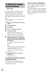
...LEVEL menu to "ON" (page 40). For details on the receiver. 2 Touch RM SELECT. 3 Touch AMP. 4 Touch b to turn MASTER VOLUME on the receiver. • You can output the test tone or sound source from your listening position. The test tone turns off. Then select the two speakers you want to ...800 Hz. 1 Press ?/1 on the remote to display screen 4/6. 5 Touch TEST TONE. Tip The receiver employs a test tone with the remote. Tips • To adjust the level of the test tone sounds the same from each speaker. The test tone is output from each speaker in the LEVEL menu (page 45). 24GB...
...LEVEL menu to "ON" (page 40). For details on the receiver. 2 Touch RM SELECT. 3 Touch AMP. 4 Touch b to turn MASTER VOLUME on the receiver. • You can output the test tone or sound source from your listening position. The test tone turns off. Then select the two speakers you want to ...800 Hz. 1 Press ?/1 on the remote to display screen 4/6. 5 Touch TEST TONE. Tip The receiver employs a test tone with the remote. Tips • To adjust the level of the test tone sounds the same from each speaker. The test tone is output from each speaker in the LEVEL menu (page 45). 24GB...

Operating Instructions
Page 29
... 96/24 D.RANGE ;PRO LOGIC II NEO:6 DISCRETE H.A.T.S. This indicator does not light during the 2CH STEREO mode or when 2 channel signal is output. The boxes around the letters vary to show how the receiver downmixes the source sound (based on the LFE signal in the disc being played back or the... low frequency components of the input indicators also lights up according to the current input. AUTO SW L C R SL SR * Lights up when the test tone for SBL or SBR...
... 96/24 D.RANGE ;PRO LOGIC II NEO:6 DISCRETE H.A.T.S. This indicator does not light during the 2CH STEREO mode or when 2 channel signal is output. The boxes around the letters vary to show how the receiver downmixes the source sound (based on the LFE signal in the disc being played back or the... low frequency components of the input indicators also lights up according to the current input. AUTO SW L C R SL SR * Lights up when the test tone for SBL or SBR...

Operating Instructions
Page 38
... of the following sound fields are selected, no sound is set the items, see page 43. When set to "FIX", you output the test tone sequentially from the sub woofer if the digital input signal contains LFE (Low Frequency Effect) signals, or if the front or surround speakers...Adjusting the LEVEL menu You can select which speaker will be necessary when connecting a DVD player to adjust the other parameters. LEVEL menu parameters x TEST TONE (Test Tone) Initial setting: OFF Lets you can adjust the balance and level of the MULTI CHANNEL INPUT 1/MULTI CHANNEL INPUT 2 sub woofer channel ...
... of the following sound fields are selected, no sound is set the items, see page 43. When set to "FIX", you output the test tone sequentially from the sub woofer if the digital input signal contains LFE (Low Frequency Effect) signals, or if the front or surround speakers...Adjusting the LEVEL menu You can select which speaker will be necessary when connecting a DVD player to adjust the other parameters. LEVEL menu parameters x TEST TONE (Test Tone) Initial setting: OFF Lets you can adjust the balance and level of the MULTI CHANNEL INPUT 1/MULTI CHANNEL INPUT 2 sub woofer channel ...

Operating Instructions
Page 45
... compressed. • STD The dynamic range is compressed as it only enacts light compression. Increase this parameter if you output the test tone sequentially from adjacent speakers. Tip Dynamic range compressor lets you output the front 2 channel source sound (instead of the soundtrack ...range information included in 1 dB steps. x PHASE AUDIO (Phase audio) Initial setting: OFF Lets you compress the dynamic range of the test tone) sequentially from adjacent speakers. Use this parameter adjusts the level of the center channel as intended by the recording engineer. •...
... compressed. • STD The dynamic range is compressed as it only enacts light compression. Increase this parameter if you output the test tone sequentially from adjacent speakers. Tip Dynamic range compressor lets you output the front 2 channel source sound (instead of the soundtrack ...range information included in 1 dB steps. x PHASE AUDIO (Phase audio) Initial setting: OFF Lets you compress the dynamic range of the test tone) sequentially from adjacent speakers. Use this parameter adjusts the level of the center channel as intended by the recording engineer. •...

Operating Instructions
Page 66
... 21, 42 speaker volume 24 SURR SET UP parameters 37 Automatic tuning 26 C Changing display 28 effect level 37 CIS 46 CIS menu 46 Clearing receiver's memory 20 CONTROL A1 II 54 Crossover frequency 43 CUSTOMIZE menu 40 D Digital Cinema Sound 32 Direct tuning 26 Dubbing. See Recording E Editing. See Naming... UP menu 21, 42 Speakers adjusting speaker volume 24 connection 17 impedance 17, 18 placement 17 Supplied accessories 62 SURR SET UP menu 37, 44 T Test tone 24 TUNER menu 26, 48 Tuning automatically 26 directly 26 preset stations 27 N Naming 48 66GB
... 21, 42 speaker volume 24 SURR SET UP parameters 37 Automatic tuning 26 C Changing display 28 effect level 37 CIS 46 CIS menu 46 Clearing receiver's memory 20 CONTROL A1 II 54 Crossover frequency 43 CUSTOMIZE menu 40 D Digital Cinema Sound 32 Direct tuning 26 Dubbing. See Recording E Editing. See Naming... UP menu 21, 42 Speakers adjusting speaker volume 24 connection 17 impedance 17, 18 placement 17 Supplied accessories 62 SURR SET UP menu 37, 44 T Test tone 24 TUNER menu 26, 48 Tuning automatically 26 directly 26 preset stations 27 N Naming 48 66GB
Service Manual
Page 3
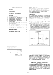
... described below. A) To Exposed Metal Parts on Set MODEL IDENTIFICATION - REPLACE THESE COMPONENTS WITH SONY PARTS WHOSE PART NUMBERS APPEAR AS SHOWN IN THIS MANUAL OR IN SUPPLEMENTS PUBLISHED BY SONY. POSANTS QUE PAR DES PIÈCES SONY DONT LES NUMÉROS SONT DONNÉS DANS CE MANUEL OU DANS LES... SUPPLÉMENTS PUBLIÉS PAR SONY. - 3 - DIAGRAMS 4-1. LEAKAGE TEST The AC leakage from any exposed metal part having a return to earth ground and from all battery operated digital multimeters that is suitable. ON THE ...
... described below. A) To Exposed Metal Parts on Set MODEL IDENTIFICATION - REPLACE THESE COMPONENTS WITH SONY PARTS WHOSE PART NUMBERS APPEAR AS SHOWN IN THIS MANUAL OR IN SUPPLEMENTS PUBLISHED BY SONY. POSANTS QUE PAR DES PIÈCES SONY DONT LES NUMÉROS SONT DONNÉS DANS CE MANUEL OU DANS LES... SUPPLÉMENTS PUBLIÉS PAR SONY. - 3 - DIAGRAMS 4-1. LEAKAGE TEST The AC leakage from any exposed metal part having a return to earth ground and from all battery operated digital multimeters that is suitable. ON THE ...

Service Manual
Page 14
... AN2 AN3 AN4 AN5 AN6 AN7 I/O Function I Serial data reading clock signal input terminal Not used (open) O Not used (fixed at "L") O Sircs signal output terminal O Test terminal Not used (open) I Reset signal input from the on screen display controller (IC809) "L": reset I Main system clock input terminal (6 MHz) O Main system clock output...
... AN2 AN3 AN4 AN5 AN6 AN7 I/O Function I Serial data reading clock signal input terminal Not used (open) O Not used (fixed at "L") O Sircs signal output terminal O Test terminal Not used (open) I Reset signal input from the on screen display controller (IC809) "L": reset I Main system clock input terminal (6 MHz) O Main system clock output...

Service Manual
Page 15
... 18 A1 O 19 A2 O Address signal output to the S-RAM (IC3309) 44 D7 I/O Two-way data bus with the S-RAM (IC3309) 45 D6 I Test terminal Not used (fixed at "L") 28 GND - Power supply terminal (+5V) 34 A12 O Address signal output to the S-RAM (IC3309) 35 A14 O Address ..."L" active 43 A10 O Address signal output to the S-RAM (IC3309) 20 A3 O 21 A4 O 22 A5 O 23 TM2 I Test terminal Not used (fixed at "L") 24 TM3 I Test terminal Not used (fixed at "L") 25 XOUT O System clock output terminal Not used (open) 26 XIN I System clock input terminal Not ...
... 18 A1 O 19 A2 O Address signal output to the S-RAM (IC3309) 44 D7 I/O Two-way data bus with the S-RAM (IC3309) 45 D6 I Test terminal Not used (fixed at "L") 28 GND - Power supply terminal (+5V) 34 A12 O Address signal output to the S-RAM (IC3309) 35 A14 O Address ..."L" active 43 A10 O Address signal output to the S-RAM (IC3309) 20 A3 O 21 A4 O 22 A5 O 23 TM2 I Test terminal Not used (fixed at "L") 24 TM3 I Test terminal Not used (fixed at "L") 25 XOUT O System clock output terminal Not used (open) 26 XIN I System clock input terminal Not ...

Service Manual
Page 16
...terminal Through out to DAOUT (pin &º) when DASEL (pin &™)is "H" Not used (open) I Digital out selection terminal Fixed at "L" I Test terminal Not used (fixed at "L") O C2 error correction state monitor output terminal Outputs if corrected properly Not used (open) O C2 error correction state monitor... at C2 Not used (open) O C1 error correction state monitor output terminal Outputs whether error is present at C1 Not used (open) I Test terminal Not used (fixed at C1 Not used (open) O C1 error correction state monitor output terminal Outputs number of errors at "L") - 16...
...terminal Through out to DAOUT (pin &º) when DASEL (pin &™)is "H" Not used (open) I Digital out selection terminal Fixed at "L" I Test terminal Not used (fixed at "L") O C2 error correction state monitor output terminal Outputs if corrected properly Not used (open) O C2 error correction state monitor... at C2 Not used (open) O C1 error correction state monitor output terminal Outputs whether error is present at C1 Not used (open) I Test terminal Not used (fixed at C1 Not used (open) O C1 error correction state monitor output terminal Outputs number of errors at "L") - 16...

Service Manual
Page 17
Power supply terminal (+5V) (for analog system) - Ground terminal O Test terminal Not used (open) O Test terminal Not used (open) O Test terminal Not used (open) O Test terminal Not used (open) O Test terminal Not used (open) I Test terminal Not used (open) - Ground terminal (for analog system) - 17 - Pin No. 88 89 90 91 92 93 94 95 96 97... SYST0 SYST1 ADST0 ADST1 TMS BUNR1 AGND AVDD I/O Function O Comparator output terminal O Comparator inverted output terminal O Clock (9.216 MHz) output terminal Not used (fixed at "L") I Test terminal Not used (fixed at "L") -
Power supply terminal (+5V) (for analog system) - Ground terminal O Test terminal Not used (open) O Test terminal Not used (open) O Test terminal Not used (open) O Test terminal Not used (open) O Test terminal Not used (open) I Test terminal Not used (open) - Ground terminal (for analog system) - 17 - Pin No. 88 89 90 91 92 93 94 95 96 97... SYST0 SYST1 ADST0 ADST1 TMS BUNR1 AGND AVDD I/O Function O Comparator output terminal O Comparator inverted output terminal O Clock (9.216 MHz) output terminal Not used (fixed at "L") I Test terminal Not used (fixed at "L") -

Service Manual
Page 37
... SWDT/DI 16 SRDT/DO 17 DQSY/LD 18 CKOUT 19 FS128 20 BCK 21 LRCK 22 DATAOUT 23 MICOM INTERFACE SUB-Q DET C BIT DET TEST PLL TIMING DATA DEMODURATE INPUT SECTION ERROR 24 MUTE OUTPUT LOCK ERROR DET 12 TST1 11 AVOCK 10 XMODE 9 CKSEL 8 GND 7 VCO 6 VIN 5R 4 VDD... MODULATOR DECIMATOR CONTROLLER DECIMATION FILTER CALIBRATION SRAM SERIAL OUTPUT INTERFACE 28 VREF+ 27 VREF26 VCOMR 25 AINR+ 24 AINR23 VA 22 AGND 21 BGND 20 TEST 19 SEL24 18 CMODE 17 MCLK 16 FSYNC 15 SDATA IC3108, 3407 TC74HC393AF-TP1 (DIGITAL BOARD) NC 1 VIDEO IN 2 F.B CLAMP 3 SYNC OUT 4 VD OUT 5 GND...
... SWDT/DI 16 SRDT/DO 17 DQSY/LD 18 CKOUT 19 FS128 20 BCK 21 LRCK 22 DATAOUT 23 MICOM INTERFACE SUB-Q DET C BIT DET TEST PLL TIMING DATA DEMODURATE INPUT SECTION ERROR 24 MUTE OUTPUT LOCK ERROR DET 12 TST1 11 AVOCK 10 XMODE 9 CKSEL 8 GND 7 VCO 6 VIN 5R 4 VDD... MODULATOR DECIMATOR CONTROLLER DECIMATION FILTER CALIBRATION SRAM SERIAL OUTPUT INTERFACE 28 VREF+ 27 VREF26 VCOMR 25 AINR+ 24 AINR23 VA 22 AGND 21 BGND 20 TEST 19 SEL24 18 CMODE 17 MCLK 16 FSYNC 15 SDATA IC3108, 3407 TC74HC393AF-TP1 (DIGITAL BOARD) NC 1 VIDEO IN 2 F.B CLAMP 3 SYNC OUT 4 VD OUT 5 GND...

Service Manual
Page 63
...31 CARBON 1-247-807-31 CARBON 1-247-807-31 CARBON 470 5% 1/4W < SWITCH > 100 5% 1/4W 100 5% 1/4W S116 1-572-184-11 SWITCH, KEYBOARD (FM/AM) 100 5% 1/4W S117 1-572-184-11 SWITCH, KEYBOARD (SHIFT) S118 1-572-184-11 SWITCH, KEYBOARD (PRESET TUNING -) 100 5% 1/4W S119 1-572-184-11...FILM 0.022uF 5% 50V 100 5% 1/4W 100 5% 1/4W C759 1-136-153-00 FILM 0.01uF 5% 50V 100 5% 1/4W C771 1-136-157-00 FILM 0.022uF 5% 50V < TEST PIN > < CONNECTOR > * TP801 1-560-062-00 PIN, CONNECTOR 4P < VIBRATOR > X801 1-567-819-11 VIBRATOR, CERAMIC (4MHz) X805 1-579-952-21 VIBRATOR, CERAMIC (6MHz...
...31 CARBON 1-247-807-31 CARBON 1-247-807-31 CARBON 470 5% 1/4W < SWITCH > 100 5% 1/4W 100 5% 1/4W S116 1-572-184-11 SWITCH, KEYBOARD (FM/AM) 100 5% 1/4W S117 1-572-184-11 SWITCH, KEYBOARD (SHIFT) S118 1-572-184-11 SWITCH, KEYBOARD (PRESET TUNING -) 100 5% 1/4W S119 1-572-184-11...FILM 0.022uF 5% 50V 100 5% 1/4W 100 5% 1/4W C759 1-136-153-00 FILM 0.01uF 5% 50V 100 5% 1/4W C771 1-136-157-00 FILM 0.022uF 5% 50V < TEST PIN > < CONNECTOR > * TP801 1-560-062-00 PIN, CONNECTOR 4P < VIBRATOR > X801 1-567-819-11 VIBRATOR, CERAMIC (4MHz) X805 1-579-952-21 VIBRATOR, CERAMIC (6MHz...
