
Service Manual
Page 1
rated 50 W per channel minimum RMS power, with 8 Ω loads both channels driven, from 250 mW to change without notice MICRO SATELLITE SYSTEM SS-V230 Front and rear speakers Speaker system Full range, magnetically shielded Speaker units 5 × 9 cm (2 × 35/8 in.), cone type Enclosure type Bass reflex Rated impedance 8 Ω Power handling capacity Maximum input power: 100 W Sensitivity level 86 dB (1W, 1m) Frequency range 90 Hz - 20,000 Hz Dimensions (w/h/d) Approx...
rated 50 W per channel minimum RMS power, with 8 Ω loads both channels driven, from 250 mW to change without notice MICRO SATELLITE SYSTEM SS-V230 Front and rear speakers Speaker system Full range, magnetically shielded Speaker units 5 × 9 cm (2 × 35/8 in.), cone type Enclosure type Bass reflex Rated impedance 8 Ω Power handling capacity Maximum input power: 100 W Sensitivity level 86 dB (1W, 1m) Frequency range 90 Hz - 20,000 Hz Dimensions (w/h/d) Approx...
Service Manual
Page 2
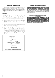
... original service problem, perform the following safety checks before releasing the set to use these instruments. 2. Leakage current can be measured by means of a passive VOM that have an accurate low-voltage scale. A battery-operated AC milliammeter. The "limit" indication is 0.75 V, so analog meters must not exceed 0.5 mA (500 microamperes). REPLACE THESE COMPONENTS WITH SONY PARTS WHOSE PART NUMBERS APPEAR...
... original service problem, perform the following safety checks before releasing the set to use these instruments. 2. Leakage current can be measured by means of a passive VOM that have an accurate low-voltage scale. A battery-operated AC milliammeter. The "limit" indication is 0.75 V, so analog meters must not exceed 0.5 mA (500 microamperes). REPLACE THESE COMPONENTS WITH SONY PARTS WHOSE PART NUMBERS APPEAR...

Service Manual
Page 3
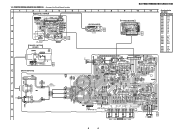
... POWER board POWER SWITCH board LED board CONTROL board MAIN board • IC Block Diagrams IC302 uPC1237H OVER LOAD DET OFFSET DET F/F VCC ON MUTE LATCH/ AUTORESET AC OFF DET 1 2 3 VCC 4 5 6 7 8 3 3 Q BCE These are in Ω and 1/4 W or less unless otherwise specified. • 2 : nonflammable resistor. • C : panel designation. Replace only with part number specified. NOTE FOR PRINTED WIRING BOARDS AND SCHEMATIC DIAGRAMS...
... POWER board POWER SWITCH board LED board CONTROL board MAIN board • IC Block Diagrams IC302 uPC1237H OVER LOAD DET OFFSET DET F/F VCC ON MUTE LATCH/ AUTORESET AC OFF DET 1 2 3 VCC 4 5 6 7 8 3 3 Q BCE These are in Ω and 1/4 W or less unless otherwise specified. • 2 : nonflammable resistor. • C : panel designation. Replace only with part number specified. NOTE FOR PRINTED WIRING BOARDS AND SCHEMATIC DIAGRAMS...
Service Manual
Page 5
... E-10 Q303 D-9 F G AC IN H T501 POWER TRANSFORMER 5 5 R SPEAKER L 11 (11) OUT LINE IN PRINTED WIRING BOARD (SA-WMS230) • See page 3 for Circuit Boards Location. 1 2 3 4 5 CONTROL BOARD A B 11 MODE (11) ON : MUSYC LEVEL OFF: MOVIE C POWER SWITCH BOARD POWER D 11 (11) E MAIN BOARD 6 7 8 LED BOARD 11 (11) (POWER) SP1 (SPEAKER) SA-VE230/WMS230/SS-CN230/V230 9 10 11 POWER BOARD 11 (11) • Semiconductor Location...
... E-10 Q303 D-9 F G AC IN H T501 POWER TRANSFORMER 5 5 R SPEAKER L 11 (11) OUT LINE IN PRINTED WIRING BOARD (SA-WMS230) • See page 3 for Circuit Boards Location. 1 2 3 4 5 CONTROL BOARD A B 11 MODE (11) ON : MUSYC LEVEL OFF: MOVIE C POWER SWITCH BOARD POWER D 11 (11) E MAIN BOARD 6 7 8 LED BOARD 11 (11) (POWER) SP1 (SPEAKER) SA-VE230/WMS230/SS-CN230/V230 9 10 11 POWER BOARD 11 (11) • Semiconductor Location...
Service Manual
Page 6
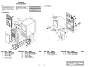
...;ro spécifié. #7 10 supplied with no reference number in the exploded views are not supplied. • Hardware (# mark) list and accessories and packing materials are seldom required for safety. No. 1 2 3 4 5 Part No. No. 55 * 56 0 T101 Part No. Replace only with part number specified. Description X-4952-542-1 FRAME ASSY, GRILLE X-4952-603-1 PANEL ASSY, FRONT 4-973-938-41 KNOB...
...;ro spécifié. #7 10 supplied with no reference number in the exploded views are not supplied. • Hardware (# mark) list and accessories and packing materials are seldom required for safety. No. 1 2 3 4 5 Part No. No. 55 * 56 0 T101 Part No. Replace only with part number specified. Description X-4952-542-1 FRAME ASSY, GRILLE X-4952-603-1 PANEL ASSY, FRONT 4-973-938-41 KNOB...

Service Manual
Page 9
SECTION 3 ELECTRICAL PARTS LIST CONTROL LED MAIN NOTE: • Due to standardization, replacements in the parts list may have some difference from the parts specified in ohms. METAL: metal-film resistor METAL OXIDE: Metal Oxide-film resistor F: nonflammable • COILS uH: µH • Abbreviation CND : Canadian model. Part No. • SEMICONDUCTORS In each case, u: µ, for routine service. Replace only with mark 0 are...
SECTION 3 ELECTRICAL PARTS LIST CONTROL LED MAIN NOTE: • Due to standardization, replacements in the parts list may have some difference from the parts specified in ohms. METAL: metal-film resistor METAL OXIDE: Metal Oxide-film resistor F: nonflammable • COILS uH: µH • Abbreviation CND : Canadian model. Part No. • SEMICONDUCTORS In each case, u: µ, for routine service. Replace only with mark 0 are...
Service Manual
Page 10
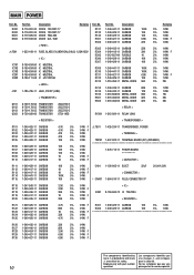
...Replace only with mark une marque 0 sont critiques 0 are critical for safety. Description 8-719-991-33 8-719-991-33 8-719-025-03 8-719-933-84 DIODE DIODE DIODE DIODE 1SS133T-77 1SS133T-77 RBA-402 UZL-15M Remarks < FUSE > 1-533-418-11 FUSE..., POWER 4.7K 5% 1/4W F 47K 5% 1/4W < TERMINAL > 47K 5% 1/4W 10K 5% 1/4W TM101 1-537-922-11 TERMINAL BOARD (SP) (SPEAKER) 10K 5% 1/4W 10K 5% 1/4W 1-676-714-11 POWER BOARD... identifiés par mark 0 or dotted line with part number Ne les remplacer que par une 10 specified. MAIN POWER Ref. D302 D303 D501 D503 0 F501 ...
...Replace only with mark une marque 0 sont critiques 0 are critical for safety. Description 8-719-991-33 8-719-991-33 8-719-025-03 8-719-933-84 DIODE DIODE DIODE DIODE 1SS133T-77 1SS133T-77 RBA-402 UZL-15M Remarks < FUSE > 1-533-418-11 FUSE..., POWER 4.7K 5% 1/4W F 47K 5% 1/4W < TERMINAL > 47K 5% 1/4W 10K 5% 1/4W TM101 1-537-922-11 TERMINAL BOARD (SP) (SPEAKER) 10K 5% 1/4W 10K 5% 1/4W 1-676-714-11 POWER BOARD... identifiés par mark 0 or dotted line with part number Ne les remplacer que par une 10 specified. MAIN POWER Ref. D302 D303 D501 D503 0 F501 ...
Service Manual
Page 11
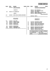
.... Part No. Description 1-676-716-11 POWER SWITCH BOARD Remarks Ref. Replace only with mark 0 are critical for safety. Description Remarks ACCESSORIES & PACKING MATERIALS < CONNECTOR > CN1 1-564-321-00 PIN, CONNECTOR 2P < SWITCH > 0 S1 1-554-920-11 SWITCH, PUSH (AC POWER)(1 KEY)(POWER) 1-558-271-11 1-769-329-21 1-769-433-11 4-226-572-11 4-226-572-21 CORD, CONNECTION CORD, CONNECTION (PIN-PIN) CORD, SPEAKER MANUAL, INSTRUCTION...
.... Part No. Description 1-676-716-11 POWER SWITCH BOARD Remarks Ref. Replace only with mark 0 are critical for safety. Description Remarks ACCESSORIES & PACKING MATERIALS < CONNECTOR > CN1 1-564-321-00 PIN, CONNECTOR 2P < SWITCH > 0 S1 1-554-920-11 SWITCH, PUSH (AC POWER)(1 KEY)(POWER) 1-558-271-11 1-769-329-21 1-769-433-11 4-226-572-11 4-226-572-21 CORD, CONNECTION CORD, CONNECTION (PIN-PIN) CORD, SPEAKER MANUAL, INSTRUCTION...
Service Manual
Page 12
SA-VE230/WMS230/SS-CN230/V230 9-929-074-11 12 Sony Corporation Home Audio Division Company 2000B1620-1D Printed in Japan © 2000.2 Published by Quality Assurance Dept.
SA-VE230/WMS230/SS-CN230/V230 9-929-074-11 12 Sony Corporation Home Audio Division Company 2000B1620-1D Printed in Japan © 2000.2 Published by Quality Assurance Dept.


