
Warranty Card
Page 1
... cover damage due to improper operation or maintenance, connection to service the Product. For your expense. 3. In-home diagnostic warranty service is invalid if the factory applied serial number has been altered or removed from your authorized dealer, call: 1-800-488-SONY (7669) Printed in material or workmanship, subject to any conditions set up adjustments or signal reception problems. This warranty does not cover cosmetic...
... cover damage due to improper operation or maintenance, connection to service the Product. For your expense. 3. In-home diagnostic warranty service is invalid if the factory applied serial number has been altered or removed from your authorized dealer, call: 1-800-488-SONY (7669) Printed in material or workmanship, subject to any conditions set up adjustments or signal reception problems. This warranty does not cover cosmetic...

Child Safety: It Makes A Difference Where Your TV Stands
Page 1
... growing trend, and larger televisions are popular purchases and not always supported on proper TV stands. Use the appropriate stand or entertainment center to support the weight, shape and size of your furniture to secure your TV (and other electronic components). Thank you home. THIS MANUFACTURER CARES! O Remember that children can become excited while watching a program and can easily be...
... growing trend, and larger televisions are popular purchases and not always supported on proper TV stands. Use the appropriate stand or entertainment center to support the weight, shape and size of your furniture to secure your TV (and other electronic components). Thank you home. THIS MANUFACTURER CARES! O Remember that children can become excited while watching a program and can easily be...
Primary User Manual
Page 1
... world of controls 3 Set-up 4 Operation 4 Presetting channels 6 Antenna/cable connection 7 Applications with other optional equipment 7 Specifications back cover Troubleshooting back cover U 0 CO C5:3 ©1985 by Sony Corporation m••=imi mni, moo mem IN= - Warning 2 Precautions 2 Features 2 Location of Sony TV. Record these numbers in the spaces provided below. OWNER'S RECORD The model and serial numbers are located at the rear. SONY® TRINITRON® COLOR TV (CABLE COMPATIBLE TV) OPERATING INSTRUCTIONS CONTENTS...
... world of controls 3 Set-up 4 Operation 4 Presetting channels 6 Antenna/cable connection 7 Applications with other optional equipment 7 Specifications back cover Troubleshooting back cover U 0 CO C5:3 ©1985 by Sony Corporation m••=imi mni, moo mem IN= - Warning 2 Precautions 2 Features 2 Location of Sony TV. Record these numbers in the spaces provided below. OWNER'S RECORD The model and serial numbers are located at the rear. SONY® TRINITRON® COLOR TV (CABLE COMPATIBLE TV) OPERATING INSTRUCTIONS CONTENTS...
Primary User Manual
Page 2
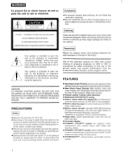
... cloth. PRECAUTIONS Safety • Operate the set with remarkably improved sharpness all the way to the screen's edges and corners. • Remote control Trinitron color television • Multi-band VHF/UHF/CATV tuning • Built-in stereo audio line inputs(L/R) for listening to external audio sources via the built-in twin speakers. • Built-in video line input for direct hook-up , do not expose the...
... cloth. PRECAUTIONS Safety • Operate the set with remarkably improved sharpness all the way to the screen's edges and corners. • Remote control Trinitron color television • Multi-band VHF/UHF/CATV tuning • Built-in stereo audio line inputs(L/R) for listening to external audio sources via the built-in twin speakers. • Built-in video line input for direct hook-up , do not expose the...
Primary User Manual
Page 3
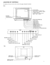
... [4] SLEEP lamp [5] VIDEO lamp [5,8] STEREO lamp [5] POWER switch [4,5] CHANNEL scan buttons [5,6] VOLUME buttons [5] TV/VIDEO button [5,6,7,8] MTS (Multichannel TV Sound) button [5,6] BALANCE control [5] BASS control [5] TREBLE control [5] AUTO STEREO switch [4,5] VIDEO/EXT-AUDIO selector [4,6,7,8] Rear CABLE switch [4,7] ADD button [6] ERASE button [6] PICTURE buttons [6] HUE control [5] COLOR control [5] BRIGHT control [5] SHARPNESS control [5] VIDEO IN jack (phono-type) [7] AUDIO IN L/R jacks (phono-type) [7,8] L_ VHF/UHF antenna terminal [4,7] 3 I L ___I On-screen display The...
... [4] SLEEP lamp [5] VIDEO lamp [5,8] STEREO lamp [5] POWER switch [4,5] CHANNEL scan buttons [5,6] VOLUME buttons [5] TV/VIDEO button [5,6,7,8] MTS (Multichannel TV Sound) button [5,6] BALANCE control [5] BASS control [5] TREBLE control [5] AUTO STEREO switch [4,5] VIDEO/EXT-AUDIO selector [4,6,7,8] Rear CABLE switch [4,7] ADD button [6] ERASE button [6] PICTURE buttons [6] HUE control [5] COLOR control [5] BRIGHT control [5] SHARPNESS control [5] VIDEO IN jack (phono-type) [7] AUDIO IN L/R jacks (phono-type) [7,8] L_ VHF/UHF antenna terminal [4,7] 3 I L ___I On-screen display The...
Primary User Manual
Page 4
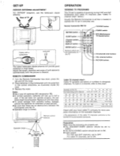
... O =I O POWER switch MTS (Multichannel TV Sound) button CH (channel) scan buttons VOL (volume) buttons PICTURE buttons The indoor telescopic dipole antenna will last up to ON. For cable TV channels, set to half a year. Remote Commander RM•728 TV/VIDEO button MUTING button SLEEP button Channel number buttons DISPLAY button ENTER button Buttons which are not duplicated on this chart. Adjust the length, direction and angle of the cable TV channels conforms to the EIA/NCTA recommended standards. Notes • Use 2 size...
... O =I O POWER switch MTS (Multichannel TV Sound) button CH (channel) scan buttons VOL (volume) buttons PICTURE buttons The indoor telescopic dipole antenna will last up to ON. For cable TV channels, set to half a year. Remote Commander RM•728 TV/VIDEO button MUTING button SLEEP button Channel number buttons DISPLAY button ENTER button Buttons which are not duplicated on this chart. Adjust the length, direction and angle of the cable TV channels conforms to the EIA/NCTA recommended standards. Notes • Use 2 size...
Primary User Manual
Page 5
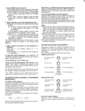
... left and right speakers respectively. To mute the sound immediately, press MUTING. The "SLEEP" indication will appear on the screen, press DISPLAY. 3 Adjust volume and picture to turn off the set automatically after one hour. The stereo sound will disappear. The MAIN and SAP sounds will light whenever a stereo broadcast is displayed. The channel number will be eliminated. • When the SAP or BOTH mode is selected...
... left and right speakers respectively. To mute the sound immediately, press MUTING. The "SLEEP" indication will appear on the screen, press DISPLAY. 3 Adjust volume and picture to turn off the set automatically after one hour. The stereo sound will disappear. The MAIN and SAP sounds will light whenever a stereo broadcast is displayed. The channel number will be eliminated. • When the SAP or BOTH mode is selected...
Primary User Manual
Page 6
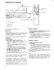
... CHANNELS ((V TV/VIDEO button I R 000 i O O --tia O O Channel number buttons ENTER button CABLE switch ADD button ERASE button CH (CHANNEL) scan buttons Receivable channels of your set are: VHF: 2-13 UHF: 14-69 CATV: 1-125 By adding and erasing channels, you can preset your TV so that only the desired channels appear in the numerical sequence. Preparation 1 Turn on the screen, indicating that the channel has been erased. ERASING CHANNELS 1 Select the channel to be connected...
... CHANNELS ((V TV/VIDEO button I R 000 i O O --tia O O Channel number buttons ENTER button CABLE switch ADD button ERASE button CH (CHANNEL) scan buttons Receivable channels of your set are: VHF: 2-13 UHF: 14-69 CATV: 1-125 By adding and erasing channels, you can preset your TV so that only the desired channels appear in the numerical sequence. Preparation 1 Turn on the screen, indicating that the channel has been erased. ERASING CHANNELS 1 Select the channel to be connected...
Primary User Manual
Page 7
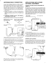
... by connecting a VCR to the antenna terminal. Rear of TV 1;6 to VHF/UHF Signal splitter FM tuner EE to antenna input to line output Tune to AUDIO IN VHF/UHF VCR output I ID simimian line output(s) video output VMC-2P3 (optional) 7 EAC-66 When the cable is split by your local cable operator. 1 Remove the indoor antenna from the antenna termi- to AUDIO IN RK-74A (optional) 1 Turn on the TV. 2 Set...
... by connecting a VCR to the antenna terminal. Rear of TV 1;6 to VHF/UHF Signal splitter FM tuner EE to antenna input to line output Tune to AUDIO IN VHF/UHF VCR output I ID simimian line output(s) video output VMC-2P3 (optional) 7 EAC-66 When the cable is split by your local cable operator. 1 Remove the indoor antenna from the antenna termi- to AUDIO IN RK-74A (optional) 1 Turn on the TV. 2 Set...
Primary User Manual
Page 8
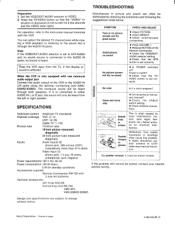
... correct channel? • Check the CABLE switch setting. • Check antenna connections. Try another channel. dication is heard. Note If the VIDEO/EXT-AUDIO selector is set to EXT-AUDIO and no sound is displayed on the screen for minimum interference. Sony Corporation Printed in picture and sound can select the desired TV channel even while viewing a VCR playback or listening to VIDEO. 2 Press the TV/VIDEO button so that the "VIDEO" in...
... correct channel? • Check the CABLE switch setting. • Check antenna connections. Try another channel. dication is heard. Note If the VIDEO/EXT-AUDIO selector is set to EXT-AUDIO and no sound is displayed on the screen for minimum interference. Sony Corporation Printed in picture and sound can select the desired TV channel even while viewing a VCR playback or listening to VIDEO. 2 Press the TV/VIDEO button so that the "VIDEO" in...


