Operating Instructions
Page 2
... "Safety and Regulatory Booklet". CAUTION Use the following two conditions: (1) This device may be determined by Sony and suitable for disconnection. SU-WL100 SU-WL500 Sony TV Stand Model No. - - Be sure to subcontract the installation to Sony dealer or licensed contractors and pay adequate attention to provide reasonable protection against harmful interference in this...
... "Safety and Regulatory Booklet". CAUTION Use the following two conditions: (1) This device may be determined by Sony and suitable for disconnection. SU-WL100 SU-WL500 Sony TV Stand Model No. - - Be sure to subcontract the installation to Sony dealer or licensed contractors and pay adequate attention to provide reasonable protection against harmful interference in this...
Operating Instructions
Page 3
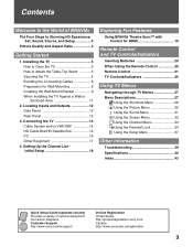
...Four Steps to Attach the Table-Top Stand 5 Securing the TV 6 Bundling the Connecting Cables 8 Preparation for Wall-Mounting 8 Installing the Wall-Mount Bracket 9 When Installing the TV Against a Wall or Enclosed Area 11 2. Installing the TV 5 How to Carry the TV 5 How to Stunning HD Experience: ...to the World of optional equipment connection diagrams. Customer Support http://www.sony.com/tvsupport On-line Registration United States http://productregistration.sony.com Canada http://www.sonystyle.ca/registration 3 Connecting the TV 14 Cable System and/or VHF/UHF 14 HD Cable Box/HD...
...Four Steps to Attach the Table-Top Stand 5 Securing the TV 6 Bundling the Connecting Cables 8 Preparation for Wall-Mounting 8 Installing the Wall-Mount Bracket 9 When Installing the TV Against a Wall or Enclosed Area 11 2. Installing the TV 5 How to Carry the TV 5 How to Stunning HD Experience: ...to the World of optional equipment connection diagrams. Customer Support http://www.sony.com/tvsupport On-line Registration United States http://productregistration.sony.com Canada http://www.sonystyle.ca/registration 3 Connecting the TV 14 Cable System and/or VHF/UHF 14 HD Cable Box/HD...
Operating Instructions
Page 5
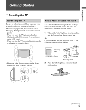
...but do not subject it securely. Accessory bag Screws TV Unit Table-top stand 2 Place the Table-Top Stand onto a level and stable surface. (Continued) 5 Install the TV unit to the Table-Top Stand before the connection and setup. 1 Take out the Table-Top Stand from the cushion and the 3 screws from children...8226; Place your hand as illustrated and hold it to Attach the Table-Top Stand The Table-Top Stand for this product is packaged separately. Do not put stress on the LCD panel. • When carrying the TV, do not squeeze the panel's speaker grill area. How to shocks or vibration...
...but do not subject it securely. Accessory bag Screws TV Unit Table-top stand 2 Place the Table-Top Stand onto a level and stable surface. (Continued) 5 Install the TV unit to the Table-Top Stand before the connection and setup. 1 Take out the Table-Top Stand from the cushion and the 3 screws from children...8226; Place your hand as illustrated and hold it to Attach the Table-Top Stand The Table-Top Stand for this product is packaged separately. Do not put stress on the LCD panel. • When carrying the TV, do not squeeze the panel's speaker grill area. How to shocks or vibration...
Operating Instructions
Page 6
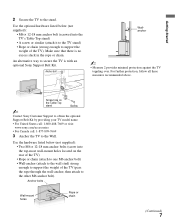
...the TV. If a Sony specified TV stand is not used as steps, such as a chest of the angle brace to the wall stud. • attach the other side to secure the stand. Use two angle braces (not supplied) to the TV stand. s Avoid placing or hanging items on the LCD ...15Kgf·cm}. For each angle brace use an electric screwdriver, set the torque for the TV. as illustrated (page 5) and hold it cannot be used , consider the following recommended measures. Use a Sony TV Stand Use a Sony specified TV stand (see page 2) and follow the instruction manual provided with supplied 3 screws. ~ •...
...the TV. If a Sony specified TV stand is not used as steps, such as a chest of the angle brace to the wall stud. • attach the other side to secure the stand. Use two angle braces (not supplied) to the TV stand. s Avoid placing or hanging items on the LCD ...15Kgf·cm}. For each angle brace use an electric screwdriver, set the torque for the TV. as illustrated (page 5) and hold it cannot be used , consider the following recommended measures. Use a Sony TV Stand Use a Sony specified TV stand (see page 2) and follow the instruction manual provided with supplied 3 screws. ~ •...
Operating Instructions
Page 7
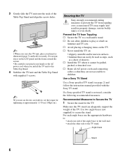
...obtain the optional Support Belt Kit by providing your TV model name. • For United States call: 1-800-488-7669 or visit: www.sony.com/accessories • For Canada call: 1-877-899-7669 3 Anchor the TV to the stand. Getting Started 2 Secure the TV to the Wall. Make sure that there is... with an optional Sony Support Belt Kit. Screw hole on the rear of the TV) • Rope or chain (attach to one M6 anchor bolt) ...
...obtain the optional Support Belt Kit by providing your TV model name. • For United States call: 1-800-488-7669 or visit: www.sony.com/accessories • For Canada call: 1-877-899-7669 3 Anchor the TV to the stand. Getting Started 2 Secure the TV to the Wall. Make sure that there is... with an optional Sony Support Belt Kit. Screw hole on the rear of the TV) • Rope or chain (attach to one M6 anchor bolt) ...
Operating Instructions
Page 8
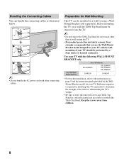
...provided by the WallMount Bracket model for your TV. Keep the screws away from the TV. ~ • Do not remove the Table-Top Stand for withstanding the TV's weight. • Be sure to the instructions on a wall by a Sony dealer or licensed contractor. Sufficient expertise is required...; For bracket installation, refer to store the removed screws and Table-Top Stand in installing this TV, especially to reattach the Table-Top Stand. Before mounting the TV on a wall, the Table-Top Stand must be performed by using a WallMount Bracket (sold separately). Sony TV Model No.
...provided by the WallMount Bracket model for your TV. Keep the screws away from the TV. ~ • Do not remove the Table-Top Stand for withstanding the TV's weight. • Be sure to the instructions on a wall by a Sony dealer or licensed contractor. Sufficient expertise is required...; For bracket installation, refer to store the removed screws and Table-Top Stand in installing this TV, especially to reattach the Table-Top Stand. Before mounting the TV on a wall, the Table-Top Stand must be performed by using a WallMount Bracket (sold separately). Sony TV Model No.
Operating Instructions
Page 9
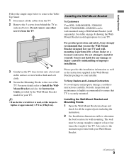
.... Do not remove any damage or injury caused by a Sony dealer or a licensed contractor. Sony is securely mounted. Please provide this installation information as well as indicated below to remove the TableTop Stand: 1 Disconnect all the required parts including the instruction. 2... See Installation dimensions table to your TV. To Sony Dealers and Licensed Contractors To avoid injury and property damage, read these...
.... Do not remove any damage or injury caused by a Sony dealer or a licensed contractor. Sony is securely mounted. Please provide this installation information as well as indicated below to remove the TableTop Stand: 1 Disconnect all the required parts including the instruction. 2... See Installation dimensions table to your TV. To Sony Dealers and Licensed Contractors To avoid injury and property damage, read these...
Operating Instructions
Page 10
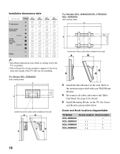
Installation dimensions table Unit: inches (mm) TV Model KDL26M4000 KDL32M4000 KDL37M4000 KDL40M4000 TV dimensions Screen center dimensions A 26 5/8 31 7/8 36 3/4 39 3/8 (675) (809) (931) (997) B 18 3/8 21 3/8 24 25 3/8 (466) (542) (609) (644) C 3 4 6 5/8 6 (75) (...instruction provided with your Wall-Mount Bracket. 4 Disconnect all cables and remove the Table- Top Stand. See Screw and Hook locations table below. Screw and Hook locations diagram/table TV Model KDL-26M4000 KDL-32M4000 KDL-37M4000 KDL-40M4000 Screw location Hook location - a f, j...
Installation dimensions table Unit: inches (mm) TV Model KDL26M4000 KDL32M4000 KDL37M4000 KDL40M4000 TV dimensions Screen center dimensions A 26 5/8 31 7/8 36 3/4 39 3/8 (675) (809) (931) (997) B 18 3/8 21 3/8 24 25 3/8 (466) (542) (609) (644) C 3 4 6 5/8 6 (75) (...instruction provided with your Wall-Mount Bracket. 4 Disconnect all cables and remove the Table- Top Stand. See Screw and Hook locations table below. Screw and Hook locations diagram/table TV Model KDL-26M4000 KDL-32M4000 KDL-37M4000 KDL-40M4000 Screw location Hook location - a f, j...
Operating Instructions
Page 11
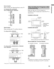
... a Wall or Enclosed Area Make sure that your TV or cause fire. 11 Getting Started Screw location When installing the Mounting Hooks on the wall 11 7/8 inches (30 cm) 4 inches (10 cm) 4 inches (10 cm) 4 inches (10 cm) Installed with stand Leave at least this much space around the set.... 11 7/8 inches (30 cm) 4 inches (10 cm) 4 inches (10 cm) 2 3/8 inches (6 cm) Leave at least this much space around the TV as follows: Air circulation is blocked. Allow enough space around the...
... a Wall or Enclosed Area Make sure that your TV or cause fire. 11 Getting Started Screw location When installing the Mounting Hooks on the wall 11 7/8 inches (30 cm) 4 inches (10 cm) 4 inches (10 cm) 4 inches (10 cm) Installed with stand Leave at least this much space around the set.... 11 7/8 inches (30 cm) 4 inches (10 cm) 4 inches (10 cm) 2 3/8 inches (6 cm) Leave at least this much space around the TV as follows: Air circulation is blocked. Allow enough space around the...
Operating Instructions
Page 42
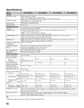
...Cable holder (1 attached to change without stand (kg/lb.) Supplied accessories Optional accessories ~ NTSC: American TV standard ATSC (8VSB terrestrial): ATSC ...compliant 8VSB QAM on cable: ANSI/SCTE 07 2000 (Does not include CableCARD functionality) Analog terrestrial: 2 - 69 / Digital terrestrial: 2 - 69 Analog Cable: 1-125 / Digital Cable: 1-135 LCD...More than 1 W 26 1,366 dots × 768 lines 146 × 35 mm 5 3/4 × 1 3/8 inches 675 × 511 × 242 (26 5/8 × 20 1/8 × 9 5/8) 675 × 466 × 97 (26 5/8 × 18...
...Cable holder (1 attached to change without stand (kg/lb.) Supplied accessories Optional accessories ~ NTSC: American TV standard ATSC (8VSB terrestrial): ATSC ...compliant 8VSB QAM on cable: ANSI/SCTE 07 2000 (Does not include CableCARD functionality) Analog terrestrial: 2 - 69 / Digital terrestrial: 2 - 69 Analog Cable: 1-125 / Digital Cable: 1-135 LCD...More than 1 W 26 1,366 dots × 768 lines 146 × 35 mm 5 3/4 × 1 3/8 inches 675 × 511 × 242 (26 5/8 × 20 1/8 × 9 5/8) 675 × 466 × 97 (26 5/8 × 18...


