
Child Safety: It Makes A Difference Where Your TV Stands
Page 1
...can potentially push or pull a TV over and may pique the children's curiosity. 6 Remember that is large enough to support the weight of your television (and other electronic components). 2 Use appropriate angle braces, straps and anchors to secure your furniture to the wall (but never screw anything directly ... your home. As a result, TV sets may fall over . 7 Share our safety message on this hidden hazard of the home with furniture and television sets. 5 Avoid placing any items on top of TVs such as VCRs and remotes that may cause unnecessary injury. Child Safety: It Makes A Difference...
...can potentially push or pull a TV over and may pique the children's curiosity. 6 Remember that is large enough to support the weight of your television (and other electronic components). 2 Use appropriate angle braces, straps and anchors to secure your furniture to the wall (but never screw anything directly ... your home. As a result, TV sets may fall over . 7 Share our safety message on this hidden hazard of the home with furniture and television sets. 5 Avoid placing any items on top of TVs such as VCRs and remotes that may cause unnecessary injury. Child Safety: It Makes A Difference...
Limited Warranty (US Only)
Page 1
... days for commercial use ) for thirty (30) inch (measured diagonally) or larger screen size television products through a SONY-authorized service facility. LIMITATION ON DAMAGES: SONY SHALL NOT BE LIABLE FOR ANY INCIDENTAL OR CONSEQUENTIAL DAMAGES FOR BREACH OF ANY EXPRESS OR IMPLIED...or refurbished parts or (ii) replace the product with the Product. 4-103-056-02(1) x S® LCD Television LIMITED WARRANTY(US ONLY) SONY ELECTRONICS INC. ("SONY") warrants this product against defects in material or workmanship for the time periods and as fuses or batteries). ...
... days for commercial use ) for thirty (30) inch (measured diagonally) or larger screen size television products through a SONY-authorized service facility. LIMITATION ON DAMAGES: SONY SHALL NOT BE LIABLE FOR ANY INCIDENTAL OR CONSEQUENTIAL DAMAGES FOR BREACH OF ANY EXPRESS OR IMPLIED...or refurbished parts or (ii) replace the product with the Product. 4-103-056-02(1) x S® LCD Television LIMITED WARRANTY(US ONLY) SONY ELECTRONICS INC. ("SONY") warrants this product against defects in material or workmanship for the time periods and as fuses or batteries). ...
Safety and Regulatory Booklet
Page 1
... to persons. Folleto de instrucciones de seguridad Lea y entienda el contenido de este folleto antes de operar su nuevo televisor. © 2008 Sony Corporation Printed in U.S.A. 3-299-071-01(1) WARNING CAUTION RISK OF ELECTRIC SHOCK DO NOT OPEN ATTENTION RISQUE DE CHOC ELECTRIQUE, NE PAS OUVRIR... NEC: National Electrical Code Antenna lead-in the Operating Instructions manual.) INSTALLATION The TV should disappear after a few moments. ☐ The LCD screen and enclosure get warm when the TV is made with high‑precision technology and to your safety. A polarized plug has two ...
... to persons. Folleto de instrucciones de seguridad Lea y entienda el contenido de este folleto antes de operar su nuevo televisor. © 2008 Sony Corporation Printed in U.S.A. 3-299-071-01(1) WARNING CAUTION RISK OF ELECTRIC SHOCK DO NOT OPEN ATTENTION RISQUE DE CHOC ELECTRIQUE, NE PAS OUVRIR... NEC: National Electrical Code Antenna lead-in the Operating Instructions manual.) INSTALLATION The TV should disappear after a few moments. ☐ The LCD screen and enclosure get warm when the TV is made with high‑precision technology and to your safety. A polarized plug has two ...
Operating Instructions
Page 1
3-876-517-11(1) LCD Digital Color TV Operating Instructions KDL-26NL140 KDL-32NL140 KDL-37NL140 © 2008 Sony Corporation
3-876-517-11(1) LCD Digital Color TV Operating Instructions KDL-26NL140 KDL-32NL140 KDL-37NL140 © 2008 Sony Corporation
Operating Instructions
Page 2
... s The TV should be installed near an easily accessible power outlet. KDL-26NL140 KDL-32NL140 KDL-37NL140 Sony Wall-Mount Bracket Model No. To Customers Sufficient expertise is a trademark....personnel before turning on the apparatus. If you to receive unscrambled digital cable television programming via subscription service to FCC regulations, you use spot lighting directed down ...717, 422 U.S. Patent No. 6, 816, 141 Blu-ray is required for help. "BRAVIA" and , , BRAVIA Theatre Sync and DMPORT are trademarks or registered trademarks of the following WALL-MOUNT BRACKET. "...
... s The TV should be installed near an easily accessible power outlet. KDL-26NL140 KDL-32NL140 KDL-37NL140 Sony Wall-Mount Bracket Model No. To Customers Sufficient expertise is a trademark....personnel before turning on the apparatus. If you to receive unscrambled digital cable television programming via subscription service to FCC regulations, you use spot lighting directed down ...717, 422 U.S. Patent No. 6, 816, 141 Blu-ray is required for help. "BRAVIA" and , , BRAVIA Theatre Sync and DMPORT are trademarks or registered trademarks of the following WALL-MOUNT BRACKET. "...
Operating Instructions
Page 3
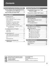
...sony.com Canada http://www.sonystyle.ca/registration 3 Installing the TV 5 How to Carry the TV 5 How to Stunning HD Experience: Set, Sound, Source, and Setup 4 Picture Quality and Aspect Ratio 4 Getting Started 1. Setting Up the Channel List Initial Setup 19 Exploring Fun Features Using BRAVIA...34 Using the Setup Menu 37 Other Information Troubleshooting 39 Specifications 42 Index 43 Quick Setup Guide (separate volume) Provides a variety of BRAVIA® The Four Steps to Attach the Table-Top Stand 5 Securing the TV 6 Bundling the Connecting Cables 7 Preparation for Wall-...
...sony.com Canada http://www.sonystyle.ca/registration 3 Installing the TV 5 How to Carry the TV 5 How to Stunning HD Experience: Set, Sound, Source, and Setup 4 Picture Quality and Aspect Ratio 4 Getting Started 1. Setting Up the Channel List Initial Setup 19 Exploring Fun Features Using BRAVIA...34 Using the Setup Menu 37 Other Information Troubleshooting 39 Specifications 42 Index 43 Quick Setup Guide (separate volume) Provides a variety of BRAVIA® The Four Steps to Attach the Table-Top Stand 5 Securing the TV 6 Bundling the Connecting Cables 7 Preparation for Wall-...

Operating Instructions
Page 4
..., enclosed separately, illustrates how to connect other external equipment Contact your cable or satellite provider for purchasing this Sony BRAVIA® high-definition television. The 1080i HD signals provide more about HDTV, visit: U.S.A http://www.sony.com/HDTV Canada http://www.sonystyle.ca/hd The Four Steps to 1080i. 4 When a 4:3 image is only as...
..., enclosed separately, illustrates how to connect other external equipment Contact your cable or satellite provider for purchasing this Sony BRAVIA® high-definition television. The 1080i HD signals provide more about HDTV, visit: U.S.A http://www.sony.com/HDTV Canada http://www.sonystyle.ca/hd The Four Steps to 1080i. 4 When a 4:3 image is only as...
Operating Instructions
Page 5
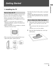
... more people. • When you carry the TV, place your palm directly underneath but do not subject it securely. Do not put stress on the LCD panel. • When carrying the TV, do not squeeze the panel's speaker grill area. (Continued) 5 Complete the following instructions to install the TV to shocks...
... more people. • When you carry the TV, place your palm directly underneath but do not subject it securely. Do not put stress on the LCD panel. • When carrying the TV, do not squeeze the panel's speaker grill area. (Continued) 5 Complete the following instructions to install the TV to shocks...
Operating Instructions
Page 6
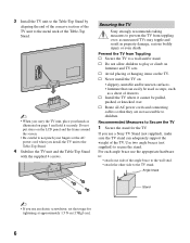
...the angle brace to the wall stud. • attach the other side to the TV stand. If you use a Sony TV Stand (not supplied), make sure the TV stand can easily be pulled, pushed, or knocked over ; Angle ... end of the concave section of the TV unit to the metal neck of drawers. Securing the TV Sony strongly recommends taking measures to prevent the TV from Toppling s Secure the TV to the Table-Top Stand... bodily injury or even death. s Never install the TV on the LCD panel and the frame around the screen. • Be careful to children. Recommended Measures to secure the stand....
...the angle brace to the wall stud. • attach the other side to the TV stand. If you use a Sony TV Stand (not supplied), make sure the TV stand can easily be pulled, pushed, or knocked over ; Angle ... end of the concave section of the TV unit to the metal neck of drawers. Securing the TV Sony strongly recommends taking measures to prevent the TV from Toppling s Secure the TV to the Table-Top Stand... bodily injury or even death. s Never install the TV on the LCD panel and the frame around the screen. • Be careful to children. Recommended Measures to secure the stand....

Operating Instructions
Page 7
Anchor bolts Bundling the Connecting Cables You can bundle the connecting cables as illustrated below (not supplied): • Two M6 × 12-18 mm anchor bolts (screw into the top-most wall-mount holes located on the rear of the TV) • Rope or chain (attach to one M6 anchor bolt) • Wall-anchor (attach to the wall stud) strong enough to support the weight of the TV (pass the rope through the wall-anchor, then attach to the other connecting cables. (Continued) 7 Wall-mount holes Rope or chain Wall- 1 anchor 2 ~ • For further protection, follow these measures to...
Anchor bolts Bundling the Connecting Cables You can bundle the connecting cables as illustrated below (not supplied): • Two M6 × 12-18 mm anchor bolts (screw into the top-most wall-mount holes located on the rear of the TV) • Rope or chain (attach to one M6 anchor bolt) • Wall-anchor (attach to the wall stud) strong enough to support the weight of the TV (pass the rope through the wall-anchor, then attach to the other connecting cables. (Continued) 7 Wall-mount holes Rope or chain Wall- 1 anchor 2 ~ • For further protection, follow these measures to...
Operating Instructions
Page 8
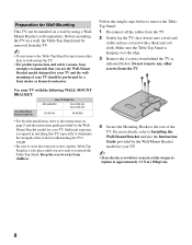
Sony TV Model No. KDL-26NL140 KDL-32NL140 KDL-37NL140 SU-WL100 SU-WL500 • For bracket installation, refer to remove the TableTop ...Top Stand in installing this TV, especially to wall-mount the TV. • For product protection and safety reasons, Sony strongly recommends that you are ready to tighten at approximately 1.5 N·m {15Kgf·cm}. 8 For more details,...Mount Bracket model for your TV. Preparation for Wall-Mounting This TV can be installed on a wall by a Sony dealer or licensed contractor. Before mounting the TV on a wall, the Table-Top Stand must be removed from ...
Sony TV Model No. KDL-26NL140 KDL-32NL140 KDL-37NL140 SU-WL100 SU-WL500 • For bracket installation, refer to remove the TableTop ...Top Stand in installing this TV, especially to wall-mount the TV. • For product protection and safety reasons, Sony strongly recommends that you are ready to tighten at approximately 1.5 N·m {15Kgf·cm}. 8 For more details,...Mount Bracket model for your TV. Preparation for Wall-Mounting This TV can be installed on a wall by a Sony dealer or licensed contractor. Before mounting the TV on a wall, the Table-Top Stand must be removed from ...
Operating Instructions
Page 9
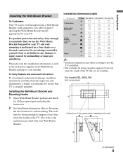
... at least four times the weight of the TV. See table on the wall (Continued) 9 Sony is performed by mishandling or improper installation. For model KDL-26NL140 Unit: inches (mm) Center line of the screen when installed on page 8 showing the ... is securely mounted. Also refer to the instruction provided with your installer. Installation dimensions table Unit: inches (mm) TV dimensions Screen center dimensions TV Model KDL-26NL140 KDL-32NL140 KDL-37NL140 A 30 3/4 (778) 36 (912) 40 1/2 (1,028) B 18 1/2 (468) 21 1/2 (543) 24 (608) C 3 3/8 (83) 6 5/8 (168) 5 1/2 (139) D ...
... at least four times the weight of the TV. See table on the wall (Continued) 9 Sony is performed by mishandling or improper installation. For model KDL-26NL140 Unit: inches (mm) Center line of the screen when installed on page 8 showing the ... is securely mounted. Also refer to the instruction provided with your installer. Installation dimensions table Unit: inches (mm) TV dimensions Screen center dimensions TV Model KDL-26NL140 KDL-32NL140 KDL-37NL140 A 30 3/4 (778) 36 (912) 40 1/2 (1,028) B 18 1/2 (468) 21 1/2 (543) 24 (608) C 3 3/8 (83) 6 5/8 (168) 5 1/2 (139) D ...

Operating Instructions
Page 10
... on the TV. Refer to the instruction provided with your Wall-Mount Bracket. 4 Disconnect all cables and remove the Table- Top Stand. For models KDL-32NL140 and KDL-37NL140 Center line of the screen when installed on the wall 3 Install the Base Bracket on the TV. a e, g c d, g b Screw... location When installing the Mounting Hooks on the wall. See page 8 for Screw and Hook locations. 10 For models KDL-32NL140 and KDL-37NL140 Unit: inches (mm) Hook locations diagram/table TV Model KDL-26NL140 KDL-32NL140 KDL-37NL140 Screw location Hook location -
... on the TV. Refer to the instruction provided with your Wall-Mount Bracket. 4 Disconnect all cables and remove the Table- Top Stand. For models KDL-32NL140 and KDL-37NL140 Center line of the screen when installed on the wall 3 Install the Base Bracket on the TV. a e, g c d, g b Screw... location When installing the Mounting Hooks on the wall. See page 8 for Screw and Hook locations. 10 For models KDL-32NL140 and KDL-37NL140 Unit: inches (mm) Hook locations diagram/table TV Model KDL-26NL140 KDL-32NL140 KDL-37NL140 Screw location Hook location -
Operating Instructions
Page 11
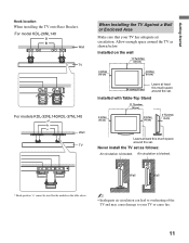
... the set. Getting Started Hook location When installing the TV onto Base Bracket. Never install the TV set . Air circulation is blocked. For model KDL-26NL140 Wall TV For models KDL-32NL140/KDL-37NL140 Wall TV When Installing the TV Against a Wall or Enclosed Area Make sure that your TV or cause fire. 11
... the set. Getting Started Hook location When installing the TV onto Base Bracket. Never install the TV set . Air circulation is blocked. For model KDL-26NL140 Wall TV For models KDL-32NL140/KDL-37NL140 Wall TV When Installing the TV Against a Wall or Enclosed Area Make sure that your TV or cause fire. 11
Operating Instructions
Page 12
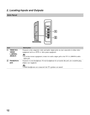
Locating Inputs and Outputs Side Panel VIDEO IN 2 VIDEO L (MONO) AUDIO R 1 2 Item 1 VIDEO IN 2 VIDEO/ L (MONO)AUDIO-R 2 Headphone jack Description Connects to the composite video and audio output jacks on your headphones do not match the jack, use a suitable plug adapter (not supplied). • While headphones are connected, the TV speakers are muted. 12 If your camcorder or other video equipment such as a DVD or video game equipment. • If you have mono equipment, connect its audio output jack to your headphones. Connects to the TV's L (MONO) audio input jack. 2.
Locating Inputs and Outputs Side Panel VIDEO IN 2 VIDEO L (MONO) AUDIO R 1 2 Item 1 VIDEO IN 2 VIDEO/ L (MONO)AUDIO-R 2 Headphone jack Description Connects to the composite video and audio output jacks on your headphones do not match the jack, use a suitable plug adapter (not supplied). • While headphones are connected, the TV speakers are muted. 12 If your camcorder or other video equipment such as a DVD or video game equipment. • If you have mono equipment, connect its audio output jack to your headphones. Connects to the TV's L (MONO) audio input jack. 2.

Operating Instructions
Page 13
For better PC view, use a DVI to HDMI cable or adapter to connect the DVI output to either HDMI IN 1 or HDMI IN 2 input, and connect the audio jacks to the AUDIO (L/R) jacks below the HDMI IN 2. (DVI connector is for 480i, 480p, 720p and 1080i signals. HDMI supports enhanced or high-definition video plus digital audio. • If the equipment has a DVI and not an HDMI connector, use the PC IN (RGB IN) input. Getting Started Rear Panel 3 4 CABLE/ ANTENNA 2 1 SERVICE ONLY 1 2 S VIDEO VIDEO L (MONO) AUDIO R 1 VIDEO IN Y IN PB PR L AUDIO R RGB R AUDIO L DIGITAL AUDIO OUT (...
For better PC view, use a DVI to HDMI cable or adapter to connect the DVI output to either HDMI IN 1 or HDMI IN 2 input, and connect the audio jacks to the AUDIO (L/R) jacks below the HDMI IN 2. (DVI connector is for 480i, 480p, 720p and 1080i signals. HDMI supports enhanced or high-definition video plus digital audio. • If the equipment has a DVI and not an HDMI connector, use the PC IN (RGB IN) input. Getting Started Rear Panel 3 4 CABLE/ ANTENNA 2 1 SERVICE ONLY 1 2 S VIDEO VIDEO L (MONO) AUDIO R 1 VIDEO IN Y IN PB PR L AUDIO R RGB R AUDIO L DIGITAL AUDIO OUT (...

Operating Instructions
Page 14
A second composite video and audio input (VIDEO IN 2) is located on your A/V equipment such as a DVD or other video equipment. Connects to the composite video and audio output jacks on the left and right audio input jacks of your audio or video equipment. Component video provides better picture quality than the DIGITAL MEDIA PORT adapter. 9 AUDIO OUT (FIX) R/L Connects to the left side panel of the TV. Connects to DIGITAL MEDIA PORT adapter (not supplied) to display photos and videos or play music from a Portable Player to your TV (see page 20 for the signals that is the case...
A second composite video and audio input (VIDEO IN 2) is located on your A/V equipment such as a DVD or other video equipment. Connects to the composite video and audio output jacks on the left and right audio input jacks of your audio or video equipment. Component video provides better picture quality than the DIGITAL MEDIA PORT adapter. 9 AUDIO OUT (FIX) R/L Connects to the left side panel of the TV. Connects to DIGITAL MEDIA PORT adapter (not supplied) to display photos and videos or play music from a Portable Player to your TV (see page 20 for the signals that is the case...

Operating Instructions
Page 15
For the best possible picture, connect these components to your TV via the HDMI or component video (with HDMI Connection HDMI cable CATV/ Satellite antenna cable HD cable box/HD satellite box Rear of TV SERVICE ONLY 1 2 S VIDEO VIDEO L (MONO) AUDIO R 1 VIDEO IN Y IN P B P R L AUDIO R RGB R AUDIO L DIGITAL AUDIO OUT (COAXIAL) R L 1 2 COMPONENT IN (1080i/720p/480p/480i) AUDIO PC IN AUDIO OUT (FIX) DMPORT (Continued) 15 A-B RF Switch Cable Antenna A Rear of input signal you will need to use an optional AB RF Switch (not supplied) to high-definition cable service ...
For the best possible picture, connect these components to your TV via the HDMI or component video (with HDMI Connection HDMI cable CATV/ Satellite antenna cable HD cable box/HD satellite box Rear of TV SERVICE ONLY 1 2 S VIDEO VIDEO L (MONO) AUDIO R 1 VIDEO IN Y IN P B P R L AUDIO R RGB R AUDIO L DIGITAL AUDIO OUT (COAXIAL) R L 1 2 COMPONENT IN (1080i/720p/480p/480i) AUDIO PC IN AUDIO OUT (FIX) DMPORT (Continued) 15 A-B RF Switch Cable Antenna A Rear of input signal you will need to use an optional AB RF Switch (not supplied) to high-definition cable service ...

Operating Instructions
Page 16
Shown with DVI Connection CATV/Satellite antenna cable Rear of TV SERVICE ONLY 1 2 S VIDEO VIDEO L (MONO) AUDIO R 1 VIDEO IN Y IN P B P R L AUDIO R RGB R AUDIO L DIGITAL AUDIO OUT (COAXIAL) R L 1 2 COMPONENT IN (1080i/720p/480p/480i) AUDIO PC IN AUDIO OUT (FIX) DMPORT Y (green) PB (blue) PR (red) AUDIO-L (white) AUDIO-R (red) Component video cable Audio cable 16 Shown with Component Connection CATV/ Satellite antenna cable HD cable box/HD satellite box Rear of TV SERVICE ONLY 1 2 S VIDEO VIDEO L (MONO) AUDIO R 1 VIDEO IN Y IN P B P R L AUDIO R RGB R AUDIO...
Shown with DVI Connection CATV/Satellite antenna cable Rear of TV SERVICE ONLY 1 2 S VIDEO VIDEO L (MONO) AUDIO R 1 VIDEO IN Y IN P B P R L AUDIO R RGB R AUDIO L DIGITAL AUDIO OUT (COAXIAL) R L 1 2 COMPONENT IN (1080i/720p/480p/480i) AUDIO PC IN AUDIO OUT (FIX) DMPORT Y (green) PB (blue) PR (red) AUDIO-L (white) AUDIO-R (red) Component video cable Audio cable 16 Shown with Component Connection CATV/ Satellite antenna cable HD cable box/HD satellite box Rear of TV SERVICE ONLY 1 2 S VIDEO VIDEO L (MONO) AUDIO R 1 VIDEO IN Y IN P B P R L AUDIO R RGB R AUDIO...

Operating Instructions
Page 17
Shown below with a 60 Hz vertical frequency from the PC according to HD15 connection. Signals VGA SVGA XGA WXGA Resolution Horizontal × Vertical (Pixel) (Line) 640 × 480 640 × 480 800 × 600 800 × 600 1,024 × 768 1,024 × 768 1,024 × 768 1,280 × 768 1,360 × 768 Horizontal frequency (kHz) 31.5 37.5 37.9 46.9 48.4 56.5 60.0 47.8 47.7 Vertical frequency (Hz) 60 75 60 75 60 70 75 60 60 Standard VGA VESA VESA Guidelines VESA VESA Guidelines VESA VESA VESA VESA ~ • This TV's PC input does not support Sync ...
Shown below with a 60 Hz vertical frequency from the PC according to HD15 connection. Signals VGA SVGA XGA WXGA Resolution Horizontal × Vertical (Pixel) (Line) 640 × 480 640 × 480 800 × 600 800 × 600 1,024 × 768 1,024 × 768 1,024 × 768 1,280 × 768 1,360 × 768 Horizontal frequency (kHz) 31.5 37.5 37.9 46.9 48.4 56.5 60.0 47.8 47.7 Vertical frequency (Hz) 60 75 60 75 60 70 75 60 60 Standard VGA VESA VESA Guidelines VESA VESA Guidelines VESA VESA VESA VESA ~ • This TV's PC input does not support Sync ...