
Operating Instructions
Page 1
3-294-082-13(1) LCD Digital Color TV KDL-26M4000 KDL-32M4000 KDL-37M4000 KDL-40M4000 © 2008 Sony Corporation Operating Instructions
3-294-082-13(1) LCD Digital Color TV KDL-26M4000 KDL-32M4000 KDL-37M4000 KDL-40M4000 © 2008 Sony Corporation Operating Instructions
Operating Instructions
Page 2
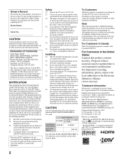
... countries. These limits are designed to provide reasonable protection against harmful interference in a place subject to safety during the installation. KDL-26M4000 KDL-32M4000 KDL-37M4000 KDL-40M4000 Sony Wall-Mount Bracket Model No. SU-WL100 SU-WL500 Sony TV Stand Model No. - - It is no guarantee that may be installed near an easily accessible power outlet. This...
... countries. These limits are designed to provide reasonable protection against harmful interference in a place subject to safety during the installation. KDL-26M4000 KDL-32M4000 KDL-37M4000 KDL-40M4000 Sony Wall-Mount Bracket Model No. SU-WL100 SU-WL500 Sony TV Stand Model No. - - It is no guarantee that may be installed near an easily accessible power outlet. This...
Operating Instructions
Page 3
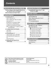
... Inserting Batteries 20 When Using the Remote Control 20 Remote Control 21 TV Controls/Indicators 25 Using TV Menus Navigating through TV Menus 27 Menu Descriptions 27 Using the Shortcuts Menu 28 Using the Picture Menu 30 Using the Sound Menu 31 Using the Screen Menu 32 Using the Channel Menu 33 Using the... 1. Locating Inputs and Outputs 12 Side Panel 12 Rear Panel 12 3. Contents Welcome to the World of optional equipment connection diagrams. Customer Support http://www.sony.com/tvsupport On-line Registration United States http://productregistration...
... Inserting Batteries 20 When Using the Remote Control 20 Remote Control 21 TV Controls/Indicators 25 Using TV Menus Navigating through TV Menus 27 Menu Descriptions 27 Using the Shortcuts Menu 28 Using the Picture Menu 30 Using the Sound Menu 31 Using the Screen Menu 32 Using the Channel Menu 33 Using the... 1. Locating Inputs and Outputs 12 Side Panel 12 Rear Panel 12 3. Contents Welcome to the World of optional equipment connection diagrams. Customer Support http://www.sony.com/tvsupport On-line Registration United States http://productregistration...
Operating Instructions
Page 4
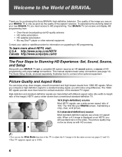
... difference. This manual explains basic setup connections (see on your BRAVIA TV set, a complete HD system requires an HD sound system, a source of the standard TV signal. The 1080i HD signals provide more about HDTV, visit: U.S.A http://www.sony.com/HDTV Canada http://www.sonystyle.ca/hd The Four Steps to... Stunning HD Experience: Set, Sound, Source, and Setup Along with your BRAVIA TV is displayed on the sides. Welcome to the World of BRAVIA® ...
... difference. This manual explains basic setup connections (see on your BRAVIA TV set, a complete HD system requires an HD sound system, a source of the standard TV signal. The 1080i HD signals provide more about HDTV, visit: U.S.A http://www.sony.com/HDTV Canada http://www.sonystyle.ca/hd The Four Steps to... Stunning HD Experience: Set, Sound, Source, and Setup Along with your BRAVIA TV is displayed on the sides. Welcome to the World of BRAVIA® ...
Operating Instructions
Page 5
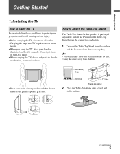
... all cables. • Carrying the large size TV requires two or more people. • When you carry the TV, place your palm directly underneath but do not subject it securely. Do not put stress on the LCD panel. • When carrying the TV, do not squeeze the panel's speaker grill area. ...Getting Started Getting Started 1. Install the TV unit to the Table-Top Stand before the connection and setup. 1 Take out the...
... all cables. • Carrying the large size TV requires two or more people. • When you carry the TV, place your palm directly underneath but do not subject it securely. Do not put stress on the LCD panel. • When carrying the TV, do not squeeze the panel's speaker grill area. ...Getting Started Getting Started 1. Install the TV unit to the Table-Top Stand before the connection and setup. 1 Take out the...
Operating Instructions
Page 6
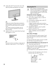
s Never install the TV on the LCD panel and the frame around the screen. • Be careful to not pinch your hand as unsecured TVs may topple and result in property damage, serious bodily injury or even death. If a Sony specified TV stand is not used as steps, such as a chest of drawers. ... cords and connecting cables so that can adequately support the weight of the TV. Securing the TV Sony strongly recommends taking measures to prevent the TV from Toppling s Secure the TV to a wall and/or stand. 3 Gently slide the TV unit onto the neck of the Table-Top Stand and align the screws ...
s Never install the TV on the LCD panel and the frame around the screen. • Be careful to not pinch your hand as unsecured TVs may topple and result in property damage, serious bodily injury or even death. If a Sony specified TV stand is not used as steps, such as a chest of drawers. ... cords and connecting cables so that can adequately support the weight of the TV. Securing the TV Sony strongly recommends taking measures to prevent the TV from Toppling s Secure the TV to a wall and/or stand. 3 Gently slide the TV unit onto the neck of the Table-Top Stand and align the screws ...
Operating Instructions
Page 7
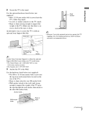
...top-most wall-mount holes located on the Table-Top stand Screw ~ Contact Sony Customer Support to obtain the optional Support Belt Kit by providing your TV model name. • For United States call: 1-800-488-7669 or visit: www.sony.com/accessories • For Canada call: 1-877-899-7669 3 Anchor ...the TV to support the weight of the TV (pass the rope through the wall-anchor, then attach...
...top-most wall-mount holes located on the Table-Top stand Screw ~ Contact Sony Customer Support to obtain the optional Support Belt Kit by providing your TV model name. • For United States call: 1-800-488-7669 or visit: www.sony.com/accessories • For Canada call: 1-877-899-7669 3 Anchor ...the TV to support the weight of the TV (pass the rope through the wall-anchor, then attach...
Operating Instructions
Page 8
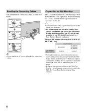
...model for Wall-Mounting This TV can bundle the connecting cables as illustrated below. ~ • Do not bundle the AC power cord with the following WALL-MOUNT BRACKET only. Sony TV Model No. Bundling the ...Connecting Cables You can be performed by using a WallMount Bracket (sold separately). Use your TV. SU-WL100 SU-WL500 • For bracket installation, refer to determine the strength of your TV should be installed on a wall by a Sony dealer or licensed contractor. KDL-26M4000 KDL-32M4000 KDL-37M4000 KDL-40M4000 Sony...
...model for Wall-Mounting This TV can bundle the connecting cables as illustrated below. ~ • Do not bundle the AC power cord with the following WALL-MOUNT BRACKET only. Sony TV Model No. Bundling the ...Connecting Cables You can be performed by using a WallMount Bracket (sold separately). Use your TV. SU-WL100 SU-WL500 • For bracket installation, refer to determine the strength of your TV should be installed on a wall by a Sony dealer or licensed contractor. KDL-26M4000 KDL-32M4000 KDL-37M4000 KDL-40M4000 Sony...
Operating Instructions
Page 9
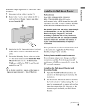
... Wall-Mount Bracket To Customers Your KDL-26M4000/KDL-32M4000/ KDL-37M4000/KDL-40M4000 can be strong enough to support at approximately 1.5 N·m {15Kgf·cm}. To Sony Dealers and Licensed Contractors To avoid injury and property damage, read these instructions carefully. For product protection and safety, Sony strongly recommends that TV is used, set the torque to...
... Wall-Mount Bracket To Customers Your KDL-26M4000/KDL-32M4000/ KDL-37M4000/KDL-40M4000 can be strong enough to support at approximately 1.5 N·m {15Kgf·cm}. To Sony Dealers and Licensed Contractors To avoid injury and property damage, read these instructions carefully. For product protection and safety, Sony strongly recommends that TV is used, set the torque to...
Operating Instructions
Page 10
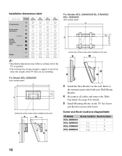
... Table- For Models KDL-32M4000/KDL-37M4000/ KDL-40M4000 Unit: inches (mm) Center line of the screen when installed on the wall For Model KDL-26M4000 Unit: inches (mm) Center line of the TV that you are installing. Installation dimensions table Unit: inches (mm) TV Model KDL26M4000 KDL32M4000 KDL37M4000 KDL40M4000 TV dimensions Screen center dimensions A 26 5/8 31 7/8 36 3/4 39...
... Table- For Models KDL-32M4000/KDL-37M4000/ KDL-40M4000 Unit: inches (mm) Center line of the screen when installed on the wall For Model KDL-26M4000 Unit: inches (mm) Center line of the TV that you are installing. Installation dimensions table Unit: inches (mm) TV Model KDL26M4000 KDL32M4000 KDL37M4000 KDL40M4000 TV dimensions Screen center dimensions A 26 5/8 31 7/8 36 3/4 39...
Operating Instructions
Page 11
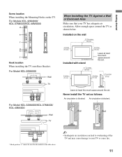
... least this much space around the TV as follows: Air circulation is blocked. Never install the TV set . Air circulation is blocked. For Models KDL-32M4000/ KDL-37M4000/KDL-40M4000 Hook location When installing the TV onto Base Bracket. For Model KDL-26M4000 Wall TV For Model KDL-32M4000/KDL-37M4000/ KDL-40M4000 Wall TV When Installing the TV Against a Wall or Enclosed Area Make...
... least this much space around the TV as follows: Air circulation is blocked. Never install the TV set . Air circulation is blocked. For Models KDL-32M4000/ KDL-37M4000/KDL-40M4000 Hook location When installing the TV onto Base Bracket. For Model KDL-26M4000 Wall TV For Model KDL-32M4000/KDL-37M4000/ KDL-40M4000 Wall TV When Installing the TV Against a Wall or Enclosed Area Make...
Operating Instructions
Page 12
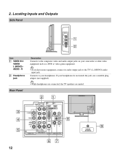
... have mono equipment, connect its audio output jack to the composite video and audio output jacks on your headphones. R 2 Headphone jack Description Connects to the TV's L (MONO) audio input jack. Locating Inputs and Outputs Side Panel VIDEO IN 2 VIDEO L (MONO) AUDIO R 1 2 Item 1 VIDEO IN 2 VIDEO/ L (MONO) AUDIO - If your headphones do...
... have mono equipment, connect its audio output jack to the composite video and audio output jacks on your headphones. R 2 Headphone jack Description Connects to the TV's L (MONO) audio input jack. Locating Inputs and Outputs Side Panel VIDEO IN 2 VIDEO L (MONO) AUDIO R 1 2 Item 1 VIDEO IN 2 VIDEO/ L (MONO) AUDIO - If your headphones do...
Operating Instructions
Page 13
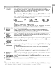
...video output connector using HD15-HD15 cable (analog RGB, not supplied). Component video provides better picture quality than composite video (4). Note that this TV displays all video input signals in a resolution of 1,366 dots × 768 lines. 2 SERVICE ONLY This USB port is PCM/Dolby ...Digital OUT (COAXIAL) compatible. 9 CABLE/ ANTENNA RF input that this TV displays all -digital audio/video interface between this TV and any HDMI-equipped audio/video equipment, such as DVD player, a set -top box's component video (YPBPR) and audio...
...video output connector using HD15-HD15 cable (analog RGB, not supplied). Component video provides better picture quality than composite video (4). Note that this TV displays all video input signals in a resolution of 1,366 dots × 768 lines. 2 SERVICE ONLY This USB port is PCM/Dolby ...Digital OUT (COAXIAL) compatible. 9 CABLE/ ANTENNA RF input that this TV displays all -digital audio/video interface between this TV and any HDMI-equipped audio/video equipment, such as DVD player, a set -top box's component video (YPBPR) and audio...

Operating Instructions
Page 14
...use an optional AB RF Switch (not supplied) to On or Off in signal degradation. 3. Shown with audio) input on the back of your TV via the HDMI or component video (with HDMI Connection HDMI cable CATV/ Satellite antenna cable HD cable box/HD satellite box 14 SERVICE ONLY 1 2... IN PB PR L AUDIO R R RGB AUDIO L DIGITAL AUDIO OUT (COAXIAL) R L 1 2 COMPONENT IN (1080i/720p/480p/480i) AUDIO PC IN AUDIO OUT (FIX) Rear of TV CABLE/ANTENNA input • It is strongly recommended that you want to watch both cable and antenna (over -the-air antenna programming, as shown. For...
...use an optional AB RF Switch (not supplied) to On or Off in signal degradation. 3. Shown with audio) input on the back of your TV via the HDMI or component video (with HDMI Connection HDMI cable CATV/ Satellite antenna cable HD cable box/HD satellite box 14 SERVICE ONLY 1 2... IN PB PR L AUDIO R R RGB AUDIO L DIGITAL AUDIO OUT (COAXIAL) R L 1 2 COMPONENT IN (1080i/720p/480p/480i) AUDIO PC IN AUDIO OUT (FIX) Rear of TV CABLE/ANTENNA input • It is strongly recommended that you want to watch both cable and antenna (over -the-air antenna programming, as shown. For...

Operating Instructions
Page 15
Shown with DVI Connection Rear of TV SERVICE ONLY 1 2 Y IN S VIDEO VIDEO L (MONO) AUDIO R 1 VIDEO IN PB PR L AUDIO R R RGB AUDIO L DIGITAL AUDIO OUT (COAXIAL) R L 1 2 COMPONENT IN (1080i/720p/480p/480i) AUDIO ...) Component video cable Audio cable (Continued) 15 Getting Started Shown with Component Connection CATV/ Satellite antenna cable HD cable box/HD satellite box Rear of TV SERVICE ONLY 1 2 Y IN S VIDEO VIDEO L (MONO) AUDIO R 1 VIDEO IN PB PR L AUDIO R R RGB AUDIO L DIGITAL AUDIO OUT (COAXIAL) R L 1 2 COMPONENT IN (1080i/720p/480p/480i) AUDIO...
Shown with DVI Connection Rear of TV SERVICE ONLY 1 2 Y IN S VIDEO VIDEO L (MONO) AUDIO R 1 VIDEO IN PB PR L AUDIO R R RGB AUDIO L DIGITAL AUDIO OUT (COAXIAL) R L 1 2 COMPONENT IN (1080i/720p/480p/480i) AUDIO ...) Component video cable Audio cable (Continued) 15 Getting Started Shown with Component Connection CATV/ Satellite antenna cable HD cable box/HD satellite box Rear of TV SERVICE ONLY 1 2 Y IN S VIDEO VIDEO L (MONO) AUDIO R 1 VIDEO IN PB PR L AUDIO R R RGB AUDIO L DIGITAL AUDIO OUT (COAXIAL) R L 1 2 COMPONENT IN (1080i/720p/480p/480i) AUDIO...
Operating Instructions
Page 16
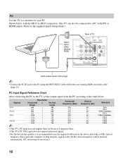
.... (PC reboot may be connected to a PC with DVI or HDMI output. (Refer to the supplied Quick Setup Guide.) HD15HD15 cable (analog RGB) Rear of TV SERVICE ONLY Y 1 2 IN S VIDEO VIDEO L (MONO) AUDIO R 1 VIDEO IN PB PR L AUDIO R R RGB AUDIO L DIGITAL AUDIO OUT (COAXIAL) R L 1 2 COMPONENT IN (1080i/720p...; 600 800 × 600 1,024 × 768 1,024 × 768 1,024 × 768 1,280 × 768 1,360 × 768 Horizontal frequency (kHz) 31.5 37.5 37.9 46.9 48.4 56.5 60.0 47.8 47.7 Vertical frequency (Hz) 60 75 60 75 60 70 75 60 60 Standard VGA VESA VESA Guidelines...
.... (PC reboot may be connected to a PC with DVI or HDMI output. (Refer to the supplied Quick Setup Guide.) HD15HD15 cable (analog RGB) Rear of TV SERVICE ONLY Y 1 2 IN S VIDEO VIDEO L (MONO) AUDIO R 1 VIDEO IN PB PR L AUDIO R R RGB AUDIO L DIGITAL AUDIO OUT (COAXIAL) R L 1 2 COMPONENT IN (1080i/720p...; 600 800 × 600 1,024 × 768 1,024 × 768 1,024 × 768 1,280 × 768 1,360 × 768 Horizontal frequency (kHz) 31.5 37.5 37.9 46.9 48.4 56.5 60.0 47.8 47.7 Vertical frequency (Hz) 60 75 60 75 60 70 75 60 60 Standard VGA VESA VESA Guidelines...

Operating Instructions
Page 17
Getting Started Other Equipment Personal computer Blu-ray Disc Player/ DVD "PS3" player Digital satellite receiver Digital cable box Audio system Headphones Camcorder Rear of TV SERVICE ONLY 1 2 Y IN S VIDEO VIDEO L (MONO) AUDIO R 1 VIDEO IN PB PR L AUDIO R R RGB AUDIO L DIGITAL AUDIO OUT (COAXIAL) R L 1 2 COMPONENT IN (1080i/720p/480p/480i) AUDIO ... Digital recorder Analog audio equipment (A/V Receiver/Home Theater) Digital audio equipment ~ • Refer to the Quick Setup Guide (supplied) when connecting other equipment to your TV. 17
Getting Started Other Equipment Personal computer Blu-ray Disc Player/ DVD "PS3" player Digital satellite receiver Digital cable box Audio system Headphones Camcorder Rear of TV SERVICE ONLY 1 2 Y IN S VIDEO VIDEO L (MONO) AUDIO R 1 VIDEO IN PB PR L AUDIO R R RGB AUDIO L DIGITAL AUDIO OUT (COAXIAL) R L 1 2 COMPONENT IN (1080i/720p/480p/480i) AUDIO ... Digital recorder Analog audio equipment (A/V Receiver/Home Theater) Digital audio equipment ~ • Refer to the Quick Setup Guide (supplied) when connecting other equipment to your TV. 17

Operating Instructions
Page 18
... page 33) when Auto Program is completed. The Initial Setup screen appears when you do it later by selecting the Auto Program option in your TV, you cancel Auto Program some channels may want to run Auto Program. If you turn on the screen to run Initial Setup, which automatically sets...; Select the proper Wide Mode as described on pages 23 and 32. ~ • You may not be available. 4 Follow the help text provided on the TV. If you need to run Auto Program later, select No. • If you can do not want to set up the channels at Channel menu...
... page 33) when Auto Program is completed. The Initial Setup screen appears when you do it later by selecting the Auto Program option in your TV, you cancel Auto Program some channels may want to run Auto Program. If you turn on the screen to run Initial Setup, which automatically sets...; Select the proper Wide Mode as described on pages 23 and 32. ~ • You may not be available. 4 Follow the help text provided on the TV. If you need to run Auto Program later, select No. • If you can do not want to set up the channels at Channel menu...

Operating Instructions
Page 19
... for an external audio system that bears the HDMI logo for HDMI This TV is turned on automatically when selected. 19 Only Sony equipment with Control for that equipment. For other Sony equipment with Control for HDMI function enables BRAVIA Theatre Sync to the respective ... Sync. When you connect a Sony A/V receiver with BRAVIA Theatre Sync function to your TV: • Automatically turn off the connected equipment when you turn off and the Picture Mode will turn on and tunes to allow communication between Sony TV's and Sony equipment. Exploring Fun Features Using ...
... for an external audio system that bears the HDMI logo for HDMI This TV is turned on automatically when selected. 19 Only Sony equipment with Control for that equipment. For other Sony equipment with Control for HDMI function enables BRAVIA Theatre Sync to the respective ... Sync. When you connect a Sony A/V receiver with BRAVIA Theatre Sync function to your TV: • Automatically turn off the connected equipment when you turn off and the Picture Mode will turn on and tunes to allow communication between Sony TV's and Sony equipment. Exploring Fun Features Using ...
Operating Instructions
Page 20
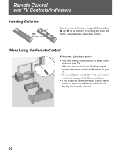
When Using the Remote Control Follow the guidelines below • Point your remote control directly at the IR sensor located on your TV. • Make sure that no objects are blocking the path between the remote control and IR sensor on the batteries to the ...turning off the fluorescent lamps. • If you are correctly inserted. 20 Remote Control and TV Controls/Indicators Inserting Batteries Push to open Insert two size AA batteries (supplied) by matching e and E on your TV. • Fluorescent lamps can interfere with the remote control, reinsert or replace your batteries and...
When Using the Remote Control Follow the guidelines below • Point your remote control directly at the IR sensor located on your TV. • Make sure that no objects are blocking the path between the remote control and IR sensor on the batteries to the ...turning off the fluorescent lamps. • If you are correctly inserted. 20 Remote Control and TV Controls/Indicators Inserting Batteries Push to open Insert two size AA batteries (supplied) by matching e and E on your TV. • Fluorescent lamps can interfere with the remote control, reinsert or replace your batteries and...


