Operating Instructions
Page 1
3-294-080-12(1) LCD Digital Color TV Operating Instructions KDL-26N4000 © 2008 Sony Corporation
3-294-080-12(1) LCD Digital Color TV Operating Instructions KDL-26N4000 © 2008 Sony Corporation
Operating Instructions
Page 2
... This Class B digital apparatus complies with part 15 of Conformity Trade Name: SONY Model: KDL-26N4000 Responsible Party: Sony Electronics Inc. TruSurround XT, SRS and ( ) symbol are trademarks of the following Sony TV only with opaque drapery. Patent No. 5, 717, 422 U.S. Model Name ...power cord specified by your authority to prevent blade exposure. KDL-26N4000 Sony Wall-Mount Bracket Model No. Availability of programming and signal provided by Sony and suitable for installing the specified TV. For disposal or recycling information, please contact your area depends...
... This Class B digital apparatus complies with part 15 of Conformity Trade Name: SONY Model: KDL-26N4000 Responsible Party: Sony Electronics Inc. TruSurround XT, SRS and ( ) symbol are trademarks of the following Sony TV only with opaque drapery. Patent No. 5, 717, 422 U.S. Model Name ...power cord specified by your authority to prevent blade exposure. KDL-26N4000 Sony Wall-Mount Bracket Model No. Availability of programming and signal provided by Sony and suitable for installing the specified TV. For disposal or recycling information, please contact your area depends...
Operating Instructions
Page 3
... 20 Using DIGITAL MEDIA PORT adapter ........ 20 Remote Control and TV Controls/Indicators Inserting Batteries 21 When Using the Remote Control 21 Remote Control 22 TV Controls/Indicators 26 Using TV Menus Navigating through TV Menus 27 Menu Descriptions 27 Using the Shortcuts Menu 28 Using... the World of optional equipment connection diagrams. Customer Support http://www.sony.com/tvsupport On-line Registration United States http://productregistration.sony.com Canada http://www.sonystyle.ca/registration 3 Connecting the TV 14 3.1 Surround Sound System 14 Cable System and/or VHF/UHF...
... 20 Using DIGITAL MEDIA PORT adapter ........ 20 Remote Control and TV Controls/Indicators Inserting Batteries 21 When Using the Remote Control 21 Remote Control 22 TV Controls/Indicators 26 Using TV Menus Navigating through TV Menus 27 Menu Descriptions 27 Using the Shortcuts Menu 28 Using... the World of optional equipment connection diagrams. Customer Support http://www.sony.com/tvsupport On-line Registration United States http://productregistration.sony.com Canada http://www.sonystyle.ca/registration 3 Connecting the TV 14 3.1 Surround Sound System 14 Cable System and/or VHF/UHF...
Operating Instructions
Page 4
... 4:3 image to fit the entire screen (see on your BRAVIA TV is displayed on an HDTV, you for information on upgrading to HD programming. The 16:9 fills your cable or satellite provider for purchasing this Sony BRAVIA® high-definition television. The quality of the image you... see pages 24 and 32). • This TV supports signals up to 1080i. 4 High-definition and standard-definition signals are transmitted with...
... 4:3 image to fit the entire screen (see on your BRAVIA TV is displayed on an HDTV, you for information on upgrading to HD programming. The 16:9 fills your cable or satellite provider for purchasing this Sony BRAVIA® high-definition television. The quality of the image you... see pages 24 and 32). • This TV supports signals up to 1080i. 4 High-definition and standard-definition signals are transmitted with...

Operating Instructions
Page 5
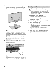
... 1 Take out the Subwoofer from the cushion and the 4 screws from the accessory bag. ~ • You will find the Subwoofer next to the TV unit. • Keep the screws away from children. 2 Place the Subwoofer onto a level and stable surface. • Place your hand as illustrated... and hold it to shocks, vibration or excessive force. Do not put stress on the LCD panel. • When carrying the TV, do not squeeze the panel's speaker grill area. (Continued) 5 The Subwoofer for this product is packaged separately. Getting Started Getting...
... 1 Take out the Subwoofer from the cushion and the 4 screws from the accessory bag. ~ • You will find the Subwoofer next to the TV unit. • Keep the screws away from children. 2 Place the Subwoofer onto a level and stable surface. • Place your hand as illustrated... and hold it to shocks, vibration or excessive force. Do not put stress on the LCD panel. • When carrying the TV, do not squeeze the panel's speaker grill area. (Continued) 5 The Subwoofer for this product is packaged separately. Getting Started Getting...
Operating Instructions
Page 6
...accessible to a wall and/or stand. 3 Install the TV unit to the Subwoofer by aligning the end of the concave section of the TV unit to play or climb on furniture and TV sets. s Avoid placing or hanging items on the LCD panel and the frame around the screen. • ...pushed, or knocked over ; Prevent the TV from Toppling s Secure the TV to children. ~ • If you install the TV unit to prevent the TV from toppling over . Do not put stress on the TV. Securing the TV Sony strongly recommends taking measures to the Subwoofer. 4 Stabilize the TV unit and the Subwoofer with the supplied ...
...accessible to a wall and/or stand. 3 Install the TV unit to the Subwoofer by aligning the end of the concave section of the TV unit to play or climb on furniture and TV sets. s Avoid placing or hanging items on the LCD panel and the frame around the screen. • ...pushed, or knocked over ; Prevent the TV from Toppling s Secure the TV to children. ~ • If you install the TV unit to prevent the TV from toppling over . Do not put stress on the TV. Securing the TV Sony strongly recommends taking measures to the Subwoofer. 4 Stabilize the TV unit and the Subwoofer with the supplied ...
Operating Instructions
Page 7
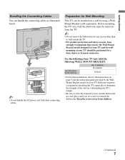
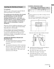
... Cables You can be installed on a wall by using a WallMount Bracket (sold separately). Before mounting the TV on page 9 and the instruction guide provided by the WallMount Bracket model for your TV. Sony Wall-Mount Bracket Model No. KDL-26N4000 SU-WL100 • For bracket installation, refer to the instructions on a wall, the Subwoofer must...
... Cables You can be installed on a wall by using a WallMount Bracket (sold separately). Before mounting the TV on page 9 and the instruction guide provided by the WallMount Bracket model for your TV. Sony Wall-Mount Bracket Model No. KDL-26N4000 SU-WL100 • For bracket installation, refer to the instructions on a wall, the Subwoofer must...
Operating Instructions
Page 8
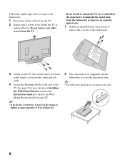
... page 9 for more details on Installing the Wall-Mount Bracket and also the Instruction Guide provided by the WallMount Bracket model for your TV. ~ • If an electric screwdriver is used, set the torque to tighten at approximately 1.5 N·m {15Kgf·cm}. 2 Place the neck cover (supplied) ... hole. ~ • The Subwoofer should not be installed on a wall, follow the steps below . Do not remove any other screws from behind the TV as indicated below to uninstall the metal neck from the Subwoofer to improve its cosmetic appearance. 1 Gently lay the Subwoofer (face down) to remove the...
... page 9 for more details on Installing the Wall-Mount Bracket and also the Instruction Guide provided by the WallMount Bracket model for your TV. ~ • If an electric screwdriver is used, set the torque to tighten at approximately 1.5 N·m {15Kgf·cm}. 2 Place the neck cover (supplied) ... hole. ~ • The Subwoofer should not be installed on a wall, follow the steps below . Do not remove any other screws from behind the TV as indicated below to uninstall the metal neck from the Subwoofer to improve its cosmetic appearance. 1 Gently lay the Subwoofer (face down) to remove the...
Operating Instructions
Page 9
... you are installing. 5 (125) Center line of the TV. Sony is securely mounted. Installation dimensions table Unit: inches TV Dimensions Screen Length for any damage or injury caused by a Sony dealer or a licensed contractor. See page 7 for your ...installer. For product protection and safety, Sony strongly recommends that TV is not liable for each mounting angle (mm) center dimensions Angle (0°) Angle (20°) Weight TV Model A B C D E F G H TV ×4 KDL- 30 3/4 18 1/2 3 3/8 13 1/2 6 3/8 10 3/4 18 13 3/4 24 lb. 96 lb. 26N4000 (778) (468) (83) (...
... you are installing. 5 (125) Center line of the TV. Sony is securely mounted. Installation dimensions table Unit: inches TV Dimensions Screen Length for any damage or injury caused by a Sony dealer or a licensed contractor. See page 7 for your ...installer. For product protection and safety, Sony strongly recommends that TV is not liable for each mounting angle (mm) center dimensions Angle (0°) Angle (20°) Weight TV Model A B C D E F G H TV ×4 KDL- 30 3/4 18 1/2 3 3/8 13 1/2 6 3/8 10 3/4 18 13 3/4 24 lb. 96 lb. 26N4000 (778) (468) (83) (...
Operating Instructions
Page 10
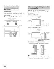
... below. Air circulation is blocked. Wall Wall ~ • Inadequate air circulation can lead to overheating of the TV and may cause damage to your TV has adequate air circulation. Hook locations diagram/table TV Model Hook location KDL-26N4000 a Screw location When installing the Mounting Hook on the wall 11 7/8 inches (30 cm) 4 inches (10...
... below. Air circulation is blocked. Wall Wall ~ • Inadequate air circulation can lead to overheating of the TV and may cause damage to your TV has adequate air circulation. Hook locations diagram/table TV Model Hook location KDL-26N4000 a Screw location When installing the Mounting Hook on the wall 11 7/8 inches (30 cm) 4 inches (10...

Operating Instructions
Page 11
Getting Started 2. Locating Inputs and Outputs Side Panel VIDEO IN 2 VIDEO L (MONO) AUDIO R 1 2 Item 1 VIDEO IN 2 VIDEO/ L (MONO)AUDIO-R 2 Headphone jack Description Connects to the TV's L (MONO) audio input jack. Connects to your camcorder or other video equipment such as a DVD or video game equipment. • If you have mono equipment, ... output jacks on your headphones. If your headphones do not match the jack, use a suitable plug adapter (not supplied). • While headphones are connected, the TV speakers are muted. (Continued) 11
Getting Started 2. Locating Inputs and Outputs Side Panel VIDEO IN 2 VIDEO L (MONO) AUDIO R 1 2 Item 1 VIDEO IN 2 VIDEO/ L (MONO)AUDIO-R 2 Headphone jack Description Connects to the TV's L (MONO) audio input jack. Connects to your camcorder or other video equipment such as a DVD or video game equipment. • If you have mono equipment, ... output jacks on your headphones. If your headphones do not match the jack, use a suitable plug adapter (not supplied). • While headphones are connected, the TV speakers are muted. (Continued) 11
Operating Instructions
Page 12
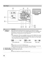
..., use the PC IN (RGB IN) input. • HDMI connection is for service only. 3 AUDIO SYSTEM Connects the Subwoofer to the TV. Note that this TV and any HDMI-equipped audio/video equipment, such as DVD player, a set-top box, A/V receiver and Blu-ray Disc player as well... Item 1 HDMI IN 1/2 R-AUDIO-L qa 67 8 9 0 Description HDMI (High-Definition Multimedia Interface) provides an uncompressed, all-digital audio/video interface between this TV displays all video input signals in a resolution of 1,366 dots × 768 lines. 2 SERVICE ONLY This USB port is necessary to view 480i, 480p, 720p...
..., use the PC IN (RGB IN) input. • HDMI connection is for service only. 3 AUDIO SYSTEM Connects the Subwoofer to the TV. Note that this TV and any HDMI-equipped audio/video equipment, such as DVD player, a set-top box, A/V receiver and Blu-ray Disc player as well... Item 1 HDMI IN 1/2 R-AUDIO-L qa 67 8 9 0 Description HDMI (High-Definition Multimedia Interface) provides an uncompressed, all-digital audio/video interface between this TV displays all video input signals in a resolution of 1,366 dots × 768 lines. 2 SERVICE ONLY This USB port is necessary to view 480i, 480p, 720p...

Operating Instructions
Page 13
... connect the audio cables. Connects to DIGITAL MEDIA PORT adapter (not supplied) to display photos and videos or play music from a Portable Player to your TV (see page 20 for the signals that can use an adapter (not supplied). Getting Started Item 4 CABLE/ ANTENNA 5 VIDEO IN 1 S VIDEO 6 VIDEO IN 1...Input Signal Reference Chart" on the left and right audio input jacks of a digital audio equipment that has S VIDEO. If this TV displays all format types of the TV. You can be displayed. 9 DMPORT • For some Apple Macintosh computers, it may be necessary to use these outputs to ...
... connect the audio cables. Connects to DIGITAL MEDIA PORT adapter (not supplied) to display photos and videos or play music from a Portable Player to your TV (see page 20 for the signals that can use an adapter (not supplied). Getting Started Item 4 CABLE/ ANTENNA 5 VIDEO IN 1 S VIDEO 6 VIDEO IN 1...Input Signal Reference Chart" on the left and right audio input jacks of a digital audio equipment that has S VIDEO. If this TV displays all format types of the TV. You can be displayed. 9 DMPORT • For some Apple Macintosh computers, it may be necessary to use these outputs to ...

Operating Instructions
Page 14
... Sound System To further enhance the sound quality, connect the Subwoofer before connecting the TV to the AUDIO SYSTEM output from the TV; if you connect any other equipment, it could cause a malfunction or damage the TV. 14 3. Subwoofer connection 1 Using DIN cable (supplied) connect the AUDIO SYSTEM... output on the rear of the TV to the AUDIO SYSTEM input on the Subwoofer as shown below. 2 Once Subwoofer installation is complete, plug the TV's and Subwoofer's AC power cord into the wall outlet. ~ • Only the supplied ...
... Sound System To further enhance the sound quality, connect the Subwoofer before connecting the TV to the AUDIO SYSTEM output from the TV; if you connect any other equipment, it could cause a malfunction or damage the TV. 14 3. Subwoofer connection 1 Using DIN cable (supplied) connect the AUDIO SYSTEM... output on the rear of the TV to the AUDIO SYSTEM input on the Subwoofer as shown below. 2 Once Subwoofer installation is complete, plug the TV's and Subwoofer's AC power cord into the wall outlet. ~ • Only the supplied ...
Operating Instructions
Page 15
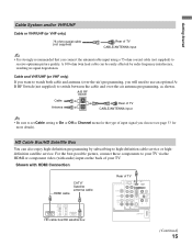
.../UHF (or VHF only) 75-ohm coaxial cable (not supplied) Rear of input signal you choose (see page 33 for the type of TV CABLE/ANTENNA input • It is strongly recommended that you connect the antenna/cable input using a 75-ohm coaxial cable (not supplied) to... picture, connect these components to switch between the cable and over-the-air antenna programming, as shown. Shown with audio) input on the back of TV SERVICE ONLY 1 2 S VIDEO VIDEO L (MONO) AUDIO R 1 VIDEO IN Y IN P B P R L AUDIO R RGB R AUDIO L DIGITAL AUDIO OUT (COAXIAL) R L 1 2 COMPONENT IN (1080i/720p/480p/...
.../UHF (or VHF only) 75-ohm coaxial cable (not supplied) Rear of input signal you choose (see page 33 for the type of TV CABLE/ANTENNA input • It is strongly recommended that you connect the antenna/cable input using a 75-ohm coaxial cable (not supplied) to... picture, connect these components to switch between the cable and over-the-air antenna programming, as shown. Shown with audio) input on the back of TV SERVICE ONLY 1 2 S VIDEO VIDEO L (MONO) AUDIO R 1 VIDEO IN Y IN P B P R L AUDIO R RGB R AUDIO L DIGITAL AUDIO OUT (COAXIAL) R L 1 2 COMPONENT IN (1080i/720p/480p/...

Operating Instructions
Page 16
Shown with DVI Connection CATV/Satellite antenna cable Rear of TV SERVICE ONLY 1 2 S VIDEO VIDEO L (MONO) AUDIO R 1 VIDEO IN Y IN P B P R L AUDIO R RGB R AUDIO L DIGITAL AUDIO OUT (COAXIAL) R L 1 2 COMPONENT IN (1080i/720p/480p/480i...-L (white) AUDIO-R (red) Component video cable Audio cable 16 Shown with Component Connection CATV/ Satellite antenna cable HD cable box/HD satellite box Rear of TV SERVICE ONLY 1 2 S VIDEO VIDEO L (MONO) AUDIO R 1 VIDEO IN Y IN P B P R L AUDIO R RGB R AUDIO L DIGITAL AUDIO OUT (COAXIAL) R L 1 2 COMPONENT IN (1080i/720p/480p/480i...
Shown with DVI Connection CATV/Satellite antenna cable Rear of TV SERVICE ONLY 1 2 S VIDEO VIDEO L (MONO) AUDIO R 1 VIDEO IN Y IN P B P R L AUDIO R RGB R AUDIO L DIGITAL AUDIO OUT (COAXIAL) R L 1 2 COMPONENT IN (1080i/720p/480p/480i...-L (white) AUDIO-R (red) Component video cable Audio cable 16 Shown with Component Connection CATV/ Satellite antenna cable HD cable box/HD satellite box Rear of TV SERVICE ONLY 1 2 S VIDEO VIDEO L (MONO) AUDIO R 1 VIDEO IN Y IN P B P R L AUDIO R RGB R AUDIO L DIGITAL AUDIO OUT (COAXIAL) R L 1 2 COMPONENT IN (1080i/720p/480p/480i...
Operating Instructions
Page 17
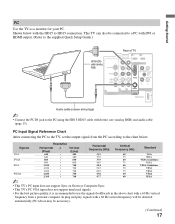
... 60 60 Standard VGA VESA VESA Guidelines VESA VESA Guidelines VESA VESA VESA VESA ~ • This TV's PC input does not support Sync on Green or Composite Sync. • This TV's PC VGA input does not support interlaced signals. • For the best picture quality, it is... will be detected automatically (PC reboot may be connected to a PC with DVI or HDMI output. (Refer to the supplied Quick Setup Guide.) Rear of TV HD15-HD15 cable (analog RGB) S VIDEO SERVICE ONLY Y P B VIDEO L (MONO) AUDIO R P R L AUDIO R 1 2 IN RGB R AUDIO L DIGITAL AUDIO OUT (COAXIAL) R L 1 VIDEO IN 1 2...
... 60 60 Standard VGA VESA VESA Guidelines VESA VESA Guidelines VESA VESA VESA VESA ~ • This TV's PC input does not support Sync on Green or Composite Sync. • This TV's PC VGA input does not support interlaced signals. • For the best picture quality, it is... will be detected automatically (PC reboot may be connected to a PC with DVI or HDMI output. (Refer to the supplied Quick Setup Guide.) Rear of TV HD15-HD15 cable (analog RGB) S VIDEO SERVICE ONLY Y P B VIDEO L (MONO) AUDIO R P R L AUDIO R 1 2 IN RGB R AUDIO L DIGITAL AUDIO OUT (COAXIAL) R L 1 VIDEO IN 1 2...

Operating Instructions
Page 18
Other Equipment Personal computer Blu-ray Disc Player/ "PS3" DVD player Digital satellite receiver Digital cable box Audio system Headphones Camcorder rear of TV SERVICE ONLY 1 2 S VIDEO VIDEO L (MONO) AUDIO R 1 VIDEO IN Y IN P B P R L AUDIO R RGB R AUDIO L DIGITAL AUDIO OUT (COAXIAL) R L 1 2 COMPONENT IN (1080i/720p/480p/480i) AUDIO PC IN ... VCR Game system Digital Analog audio equipment recorder (A/V Receiver/Home Theater) ~ • Refer to the Quick Setup Guide (supplied) when connecting other equipment to your TV. 18
Other Equipment Personal computer Blu-ray Disc Player/ "PS3" DVD player Digital satellite receiver Digital cable box Audio system Headphones Camcorder rear of TV SERVICE ONLY 1 2 S VIDEO VIDEO L (MONO) AUDIO R 1 VIDEO IN Y IN P B P R L AUDIO R RGB R AUDIO L DIGITAL AUDIO OUT (COAXIAL) R L 1 2 COMPONENT IN (1080i/720p/480p/480i) AUDIO PC IN ... VCR Game system Digital Analog audio equipment recorder (A/V Receiver/Home Theater) ~ • Refer to the Quick Setup Guide (supplied) when connecting other equipment to your TV. 18
Operating Instructions
Page 19
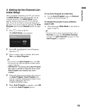
... select Yes to run Auto Program. ~ • If you want to run Initial Setup, which automatically sets up convenient features such as described on the TV. If you have both cable and antenna available, please connect cable first. • IMPORTANT: You must perform Auto Program after cable or antenna is complete... turn on page 33. Auto Program will scan for available channels from signal source directly connected to the TV's CABLE/ANTENNA input. 5 When Auto Program is connected. If you can do not want to set up available channels. The Initial Setup screen appears when ...
... select Yes to run Auto Program. ~ • If you want to run Initial Setup, which automatically sets up convenient features such as described on the TV. If you have both cable and antenna available, please connect cable first. • IMPORTANT: You must perform Auto Program after cable or antenna is complete... turn on page 33. Auto Program will scan for available channels from signal source directly connected to the TV's CABLE/ANTENNA input. 5 When Auto Program is connected. If you can do not want to set up available channels. The Initial Setup screen appears when ...
Operating Instructions
Page 20
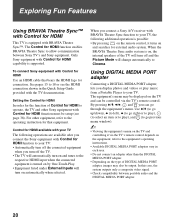
... adapter. • Depending on the type of DIGITAL MEDIA PORT adapter, images may be setup (see page 38). Only Sony equipment with the TV documentation. To connect Sony equipment with Control for connection. Setting the Control for HDMI In order for the function of the... the internal speakers of Control for HDMI to operate, the TV and other equipment, refer to your TV. In this case, the system outputs only a composite video signal. • Check compatibility between Sony TV's and Sony equipment. For other Sony equipment with Control for HDMI Use an HDMI cable that equipment....
... adapter. • Depending on the type of DIGITAL MEDIA PORT adapter, images may be setup (see page 38). Only Sony equipment with the TV documentation. To connect Sony equipment with Control for connection. Setting the Control for HDMI In order for the function of the... the internal speakers of Control for HDMI to operate, the TV and other equipment, refer to your TV. In this case, the system outputs only a composite video signal. • Check compatibility between Sony TV's and Sony equipment. For other Sony equipment with Control for HDMI Use an HDMI cable that equipment....


