
Operating Instructions
Page 1
4-445-037-11 (1) Power Supply Unit Operating Instructions Before operating the unit, please read this manual thoroughly and retain it for future reference. HXCE-FB70 © 2012 Sony Corporation
4-445-037-11 (1) Power Supply Unit Operating Instructions Before operating the unit, please read this manual thoroughly and retain it for future reference. HXCE-FB70 © 2012 Sony Corporation

Operating Instructions
Page 2
.... 3 in which case the user will be required to the safety regulations of each country if applicable. 2. Refer servicing to the proper ratings (Voltage, Ampere). If used in the U.S.A. WARNING: THIS WARNING IS APPLICABLE FOR OTHER COUNTRIES. 1. Use the approved Power Cord (3core mains lead)/Appliance Connector/Plug with the limits for a Class A digital device, pursuant to rain or moisture...
.... 3 in which case the user will be required to the safety regulations of each country if applicable. 2. Refer servicing to the proper ratings (Voltage, Ampere). If used in the U.S.A. WARNING: THIS WARNING IS APPLICABLE FOR OTHER COUNTRIES. 1. Use the approved Power Cord (3core mains lead)/Appliance Connector/Plug with the limits for a Class A digital device, pursuant to rain or moisture...

Operating Instructions
Page 3
... product is Sony Corporation, 1-7-1 Konan, Minato-ku, Tokyo, 108-0075 Japan. This device complies with the EMC Directive issued by the Commission of the FCC Rules. For the customers in Europe, Australia and New Zealand WARNING This is Sony Deutschland GmbH, Hedelfinger Strasse 61, 70327 Stuttgart, Germany. The Authorized Representative for use in which case the user...
... product is Sony Corporation, 1-7-1 Konan, Minato-ku, Tokyo, 108-0075 Japan. This device complies with the EMC Directive issued by the Commission of the FCC Rules. For the customers in Europe, Australia and New Zealand WARNING This is Sony Deutschland GmbH, Hedelfinger Strasse 61, 70327 Stuttgart, Germany. The Authorized Representative for use in which case the user...
Operating Instructions
Page 4
Table of Contents Overview 5 Names and Functions of Parts 6 System Configuration 8 Important Notes on Operation 9 Specifications 10 General 10 Supplied Accessories 10 Optional Accessories 10 Other peripheral devices 11 4 Table of Contents
Table of Contents Overview 5 Names and Functions of Parts 6 System Configuration 8 Important Notes on Operation 9 Specifications 10 General 10 Supplied Accessories 10 Optional Accessories 10 Other peripheral devices 11 4 Table of Contents
Operating Instructions
Page 5
... available distance for power supply varies depending on the model of the CA-FB70. 5 Overview For details, see the operating instructions of the camera/camcorder that are connected to the CA-FB70. Overview The HXCE-FB70 Power Supply Unit connects to the HXCU-FB70 HD Camera Control Unit and CA-FB70 HD Camera Adaptor, and supplies power to the CA-FB70, and total power consumption of the connected peripherals of...
... available distance for power supply varies depending on the model of the CA-FB70. 5 Overview For details, see the operating instructions of the camera/camcorder that are connected to the CA-FB70. Overview The HXCE-FB70 Power Supply Unit connects to the HXCU-FB70 HD Camera Control Unit and CA-FB70 HD Camera Adaptor, and supplies power to the CA-FB70, and total power consumption of the connected peripherals of...
Operating Instructions
Page 6
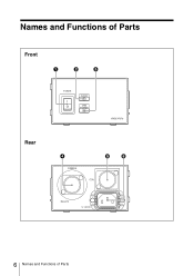
Names and Functions of Parts Front Rear 6 Names and Functions of Parts
Names and Functions of Parts Front Rear 6 Names and Functions of Parts
Operating Instructions
Page 7
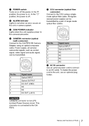
... signal, can be transmitted. Pin No. This connector is off the power. To fasten the power cord to the CA-FB70 HD Camera Adaptor using a singlemode optical fiber cable. c CAM POWER indicator Lights when the unit supplies power to an AC outlet. Signal name A Optical INPUT B Optical OUTPUT 1 NC 2 NC 3 NC 4 NC f AC IN connector Use an optional power cord to connect to the camera/camcorder. e CCU...
... signal, can be transmitted. Pin No. This connector is off the power. To fasten the power cord to the CA-FB70 HD Camera Adaptor using a singlemode optical fiber cable. c CAM POWER indicator Lights when the unit supplies power to an AC outlet. Signal name A Optical INPUT B Optical OUTPUT 1 NC 2 NC 3 NC 4 NC f AC IN connector Use an optional power cord to connect to the camera/camcorder. e CCU...
Operating Instructions
Page 8
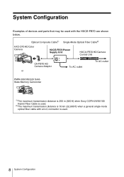
System Configuration Examples of devices and parts that may be used with an LC connector is used . 2) The maximum transmission distance is used . 8 System Configuration Optical Composite Cable1) Single-Mode Optical Fiber Cable2) HXC-D70 HD Color Camera HXCE-FB70 Power Supply Unit HXCU-FB70 HD Camera Control Unit CA-FB70 HD Camera Adaptor or To AC outlet To AC outlet PMW-500/350/320...
System Configuration Examples of devices and parts that may be used with an LC connector is used . 2) The maximum transmission distance is used . 8 System Configuration Optical Composite Cable1) Single-Mode Optical Fiber Cable2) HXC-D70 HD Color Camera HXCE-FB70 Power Supply Unit HXCU-FB70 HD Camera Control Unit CA-FB70 HD Camera Adaptor or To AC outlet To AC outlet PMW-500/350/320...

Operating Instructions
Page 9
...shown in warm climates the temperature inside a car with a fiber optic cleaner before connection. If the end of neutral detergent, then wipe dry. On placement When using or storing the adaptor in a level, ventilated place. Avoid using the adaptor, be sure to place it to 104&#...176;F). • Remember that in summer in the below figure. 9 Important Notes on Operation Maintenance Clean the cabinet and panels by wiping lightly with a small amount of the cable...
...shown in warm climates the temperature inside a car with a fiber optic cleaner before connection. If the end of neutral detergent, then wipe dry. On placement When using or storing the adaptor in a level, ventilated place. Avoid using the adaptor, be sure to place it to 104&#...176;F). • Remember that in summer in the below figure. 9 Important Notes on Operation Maintenance Clean the cabinet and panels by wiping lightly with a small amount of the cable...
Operating Instructions
Page 10
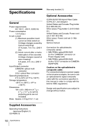
... change without notice. Specifications General Power requirements AC 100 V - 240 V, 50/60 Hz Power consumption 1.5 A (max.) Inrush current (1) Maximum possible inrush current at initial switch-on the optical/electric composite cable: For connection between a power supply unit and camera adaptor, be sure to use an optical/electric signal composite cable with the limit for EMC regulations. Supplied Accessories Operating Instructions Japanese/English (1) CD...
... change without notice. Specifications General Power requirements AC 100 V - 240 V, 50/60 Hz Power consumption 1.5 A (max.) Inrush current (1) Maximum possible inrush current at initial switch-on the optical/electric composite cable: For connection between a power supply unit and camera adaptor, be sure to use an optical/electric signal composite cable with the limit for EMC regulations. Supplied Accessories Operating Instructions Japanese/English (1) CD...
Operating Instructions
Page 11
SONY WILL NOT BE LIABLE FOR DAMAGES OF ANY KIND INCLUDING, BUT NOT LIMITED TO, COMPENSATION OR REIMBURSEMENT ON ACCOUNT OF THE LOSS OF PRESENT OR PROSPECTIVE PROFITS DUE TO FAILURE OF THIS UNIT, EITHER DURING THE WARRANTY PERIOD OR AFTER EXPIRATION OF THE WARRANTY, OR FOR ANY OTHER REASON WHATSOEVER. Note Always verify that the unit is operating properly before use. Other peripheral devices CA-FB70 HD Camera Adaptor HXCU-FB70 HD Camera Control Unit 11 Specifications
SONY WILL NOT BE LIABLE FOR DAMAGES OF ANY KIND INCLUDING, BUT NOT LIMITED TO, COMPENSATION OR REIMBURSEMENT ON ACCOUNT OF THE LOSS OF PRESENT OR PROSPECTIVE PROFITS DUE TO FAILURE OF THIS UNIT, EITHER DURING THE WARRANTY PERIOD OR AFTER EXPIRATION OF THE WARRANTY, OR FOR ANY OTHER REASON WHATSOEVER. Note Always verify that the unit is operating properly before use. Other peripheral devices CA-FB70 HD Camera Adaptor HXCU-FB70 HD Camera Control Unit 11 Specifications
