Product Manual (HVE-1500A Operating Manuals)
Page 5
Table of Contents Chapter 1 Overview Features 8 HDV format 8 DVCAM/DV format 8 Variety of interfaces 9 Other features 9 Using the CD-ROM Manual 11 Preparations 11 Reading the CD-ROM Manual 11 Names and ... Data and Operating Mode 33 Displaying on the LCD monitor and an external video monitor ......... 33 Recording Formats and Input/Output Signals 35 Differences among HDV 1080i, DVCAM, and DV formats 35 Input and output signals in E-E mode 35 Playback formats and output signals 38 Usable Cassettes 40 Inserting and ejecting...
Table of Contents Chapter 1 Overview Features 8 HDV format 8 DVCAM/DV format 8 Variety of interfaces 9 Other features 9 Using the CD-ROM Manual 11 Preparations 11 Reading the CD-ROM Manual 11 Names and ... Data and Operating Mode 33 Displaying on the LCD monitor and an external video monitor ......... 33 Recording Formats and Input/Output Signals 35 Differences among HDV 1080i, DVCAM, and DV formats 35 Input and output signals in E-E mode 35 Playback formats and output signals 38 Usable Cassettes 40 Inserting and ejecting...
Product Manual (HVE-1500A Operating Manuals)
Page 6
... external device 48 Repeat playback - automatic cyclical playback 48 Setting points A and B for repeat playback 49 Cuing up to any desired position set as an HDV tape player 63 When using this unit as point A or B 51 Chapter 4 Using Time Data Recording Timecode and User Bit Data 52 Setting the timecode... recording 42 Carrying out recording 44 Playback 46 Settings for Dubbing and TC Insert Digital Dubbing 66 Connections and settings 66 Digitally dubbing signals in HDV/DVCAM/DV format 67 Rerecording the Timecode -
... external device 48 Repeat playback - automatic cyclical playback 48 Setting points A and B for repeat playback 49 Cuing up to any desired position set as an HDV tape player 63 When using this unit as point A or B 51 Chapter 4 Using Time Data Recording Timecode and User Bit Data 52 Setting the timecode... recording 42 Carrying out recording 44 Playback 46 Settings for Dubbing and TC Insert Digital Dubbing 66 Connections and settings 66 Digitally dubbing signals in HDV/DVCAM/DV format 67 Rerecording the Timecode -
Product Manual (HVE-1500A Operating Manuals)
Page 8
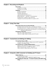
... video recording bitrate is a 1/4-inch professional digital recording format developed by Sony. For details, see "Recording Formats and Input/Output Signals" (page 35). With this unit you can be selected from an HDV, DVCAM or DV format cassette. For details, see "Recording Formats and... (60i)/4:2:0 (50i) component digital consumer DV format, DVCAM is approximately 25 Mbps. The SDI input connector of Sony Corporation. High-performance down-conversion function When playing a tape recorded in HDV 1080/60i and HDV 1080/50i formats, image size 1440 × 1080 pixels).
... video recording bitrate is a 1/4-inch professional digital recording format developed by Sony. For details, see "Recording Formats and Input/Output Signals" (page 35). With this unit you can be selected from an HDV, DVCAM or DV format cassette. For details, see "Recording Formats and... (60i)/4:2:0 (50i) component digital consumer DV format, DVCAM is approximately 25 Mbps. The SDI input connector of Sony Corporation. High-performance down-conversion function When playing a tape recorded in HDV 1080/60i and HDV 1080/50i formats, image size 1440 × 1080 pixels).
Product Manual (HVE-1500A Operating Manuals)
Page 9
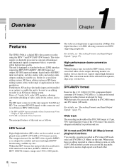
... required. However, 60i/50i format conversion is not supported. 1) Note that for this unit. Compact design, with a computer, or uploading from HDV recorded tapes or HD-SDI signals as HDSDI signals (upconvert function). The unit also accepts standard (L) and medium (M) sizes of DVCPRO cassette. &#... output connectors are supported. Support for three cassette sizes There are provided as standard so that when playing a tape recorded in HDV format a downconverted signal can readily be used to the size of interfaces Digital interfaces The following analog interfaces. This output can ...
... required. However, 60i/50i format conversion is not supported. 1) Note that for this unit. Compact design, with a computer, or uploading from HDV recorded tapes or HD-SDI signals as HDSDI signals (upconvert function). The unit also accepts standard (L) and medium (M) sizes of DVCPRO cassette. &#... output connectors are supported. Support for three cassette sizes There are provided as standard so that when playing a tape recorded in HDV format a downconverted signal can readily be used to the size of interfaces Digital interfaces The following analog interfaces. This output can ...
Product Manual (HVE-1500A Operating Manuals)
Page 10
... setup level and chroma phase. Cross-convert function: When HD video signals are input, or when SD video signals are upconverted, or when HDV recorded tapes are each used to other problems. It also displays a description of SD reference signals and HD reference signals (1080i tri-level ...played back, the HDSDI output signal format can be displayed on the monitor screen or the time counter display. Note Consult your Sony dealer or a Sony service representative for SD-SDI input and output or HD-SDI input and output. Reference signal connection The reference video input connector of...
... setup level and chroma phase. Cross-convert function: When HD video signals are input, or when SD video signals are upconverted, or when HDV recorded tapes are each used to other problems. It also displays a description of SD reference signals and HD reference signals (1080i tri-level ...played back, the HDSDI output signal format can be displayed on the monitor screen or the time counter display. Note Consult your Sony dealer or a Sony service representative for SD-SDI input and output or HD-SDI input and output. Reference signal connection The reference video input connector of...

Product Manual (HVE-1500A Operating Manuals)
Page 12
... -40 -60 CH1 CH2 EDIT MODE REPEAT TC VITC 48K 01:23:45:15 DISPLAY COUNTER SELECT PLAY F FWD STOP REC LOCAL 9PIN i.LINK MENU HDV DVCAM (DV) ASSIGN RESET(NO) TC PRESET SET(YES) A B 7 EJECT button 8 RESET (NO) button 9 SET (YES) button 5 CONTROL-S connector 3 LCD monitor (see page 19) a POWER... -40 -60 CH1 CH2 EDIT MODE REPEAT TC VITC 48K 01:23:45:15 DISPLAY COUNTER SELECT PLAY F FWD STOP REC LOCAL 9PIN i.LINK MENU HDV DVCAM (DV) ASSIGN RESET(NO) TC PRESET SET(YES) A B 4 Remote control switch/ indicator section (see page 19) 5 Arrow buttons (see page 16...
... -40 -60 CH1 CH2 EDIT MODE REPEAT TC VITC 48K 01:23:45:15 DISPLAY COUNTER SELECT PLAY F FWD STOP REC LOCAL 9PIN i.LINK MENU HDV DVCAM (DV) ASSIGN RESET(NO) TC PRESET SET(YES) A B 7 EJECT button 8 RESET (NO) button 9 SET (YES) button 5 CONTROL-S connector 3 LCD monitor (see page 19) a POWER... -40 -60 CH1 CH2 EDIT MODE REPEAT TC VITC 48K 01:23:45:15 DISPLAY COUNTER SELECT PLAY F FWD STOP REC LOCAL 9PIN i.LINK MENU HDV DVCAM (DV) ASSIGN RESET(NO) TC PRESET SET(YES) A B 4 Remote control switch/ indicator section (see page 19) 5 Arrow buttons (see page 16...
Product Manual (HVE-1500A Operating Manuals)
Page 13
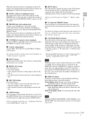
...) button Press this button cycles through the following three display modes of Parts f Cassette compartment Accepts HDV, DVCAM, DV and DVCPRO (25 Mbps) videocassettes. Press this unit is connected to the REMOTE connector or HDV/DV connector on the rear panel. Note When the remote control switch on this button to the...
...) button Press this button cycles through the following three display modes of Parts f Cassette compartment Accepts HDV, DVCAM, DV and DVCPRO (25 Mbps) videocassettes. Press this unit is connected to the REMOTE connector or HDV/DV connector on the rear panel. Note When the remote control switch on this button to the...
Product Manual (HVE-1500A Operating Manuals)
Page 14
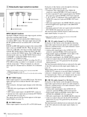
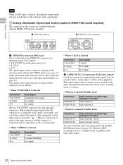
... HVBK-1505 board required) • SDI video signal input to the SD/HD SDI IN connector • DV/DVCAM format signal input to the HDV/DV connector 1) • Internally generated video test signal (selected with the INT VIDEO SG menu item (see page 81)) The selection made with this... 2 or 4 channels, as channels 1/2 or channels 3/4. 1) Make the DVCAM/DV recording format selection with the setup menu. 2) When 4 channels are input to the HDV/DV connector • Internal test video signal selected with the INT VIDEO SG menu item (see page 81) The signal selected with this connector is...
... HVBK-1505 board required) • SDI video signal input to the SD/HD SDI IN connector • DV/DVCAM format signal input to the HDV/DV connector 1) • Internally generated video test signal (selected with the INT VIDEO SG menu item (see page 81)) The selection made with this... 2 or 4 channels, as channels 1/2 or channels 3/4. 1) Make the DVCAM/DV recording format selection with the setup menu. 2) When 4 channels are input to the HDV/DV connector • Internal test video signal selected with the INT VIDEO SG menu item (see page 81) The signal selected with this connector is...
Product Manual (HVE-1500A Operating Manuals)
Page 15
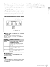
... set to the AUDIO IN 2/4 connector is recorded either on channel 2 (when in 2- Notes • When selecting an i.LINK (HDV) input to record signals in HDV format, it is possible to adjust the audio levels on channels 1 to 4 during playback. You can switch the audio recording mode with...knobs used to 4 during recording. The analog audio input/output levels are disabled, and the input/ output levels become fixed. That is, in HDV format to the DVCAM/DV format using the i.LINK output, the adjustments of the VARIABLE switch as follows. Chapter 1 Overview When analog audio is...
... set to the AUDIO IN 2/4 connector is recorded either on channel 2 (when in 2- Notes • When selecting an i.LINK (HDV) input to record signals in HDV format, it is possible to adjust the audio levels on channels 1 to 4 during playback. You can switch the audio recording mode with...knobs used to 4 during recording. The analog audio input/output levels are disabled, and the input/ output levels become fixed. That is, in HDV format to the DVCAM/DV format using the i.LINK output, the adjustments of the VARIABLE switch as follows. Chapter 1 Overview When analog audio is...

Product Manual (HVE-1500A Operating Manuals)
Page 17
... is installed in the unit. • When HD VIDEO input is selected Video area display SG:HD HD SDI i.LINK:HDV Signal format HD test signal HD-SDI video signal 1) i.LINK compatible HDV format video/ audio signal 1) Downconverted signals (analog video output) are output from the VIDEO OUT connectors. • When SD...
... is installed in the unit. • When HD VIDEO input is selected Video area display SG:HD HD SDI i.LINK:HDV Signal format HD test signal HD-SDI video signal 1) i.LINK compatible HDV format video/ audio signal 1) Downconverted signals (analog video output) are output from the VIDEO OUT connectors. • When SD...
Product Manual (HVE-1500A Operating Manuals)
Page 18
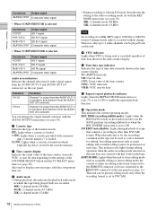
... data shown in the time counter display. However, only up to enable the repeat playback function. j Time data type indicator Indicates the type of i.LINK (HDV) input, 1080/60i or 1080/50i format 4-channel mode audio is output from the AUDIO OUT 1/ 3 connector, and channel 2 from the AUDIO OUT 2/4 ... or when in E-E mode, this indicates the setting of the audio recording mode set with a memory chip ("cassette memory") is set to the HDV/DV connector on the settings of the COUNTER SELECT button and the TC SELECT menu item (see page 85). This unit can change . This indicator...
... data shown in the time counter display. However, only up to enable the repeat playback function. j Time data type indicator Indicates the type of i.LINK (HDV) input, 1080/60i or 1080/50i format 4-channel mode audio is output from the AUDIO OUT 1/ 3 connector, and channel 2 from the AUDIO OUT 2/4 ... or when in E-E mode, this indicates the setting of the audio recording mode set with a memory chip ("cassette memory") is set to the HDV/DV connector on the settings of the COUNTER SELECT button and the TC SELECT menu item (see page 85). This unit can change . This indicator...
Product Manual (HVE-1500A Operating Manuals)
Page 19
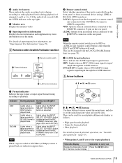
...When the remote control switch is set in the menu. c i.LINK format indicators These indicate the i.LINK input/output signal format. HDV: Lights when an HDV 1080i format signal is input/output through the i.LINK interface. LOCAL: Operate from the front panel or a remote control unit connected... control buttons other than the EJECT and STOP buttons will work. For details of superimposed text information, see page 76). HDV DVCAM (DV) 5 Arrow buttons 3 i.LINK format indicators M, m, o Superimposed text information Displays the text information and supplementary status information set ...
...When the remote control switch is set in the menu. c i.LINK format indicators These indicate the i.LINK input/output signal format. HDV: Lights when an HDV 1080i format signal is input/output through the i.LINK interface. LOCAL: Operate from the front panel or a remote control unit connected... control buttons other than the EJECT and STOP buttons will work. For details of superimposed text information, see page 76). HDV DVCAM (DV) 5 Arrow buttons 3 i.LINK format indicators M, m, o Superimposed text information Displays the text information and supplementary status information set ...
Product Manual (HVE-1500A Operating Manuals)
Page 21
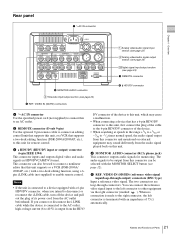
... to this unit for monitoring. e REF. This connector can connect the reference video signal input to the left connector is output from the HDV/ DV connector of the device to this unit, which may sound differently from the audio signal played back on external equipment may cause a ... When connecting a device that this unit supports or a VCR (DSR-2000A/ 2000AP, etc.) with the MONITOR SELECT button (see page 12). c HDV/DV (HDV/DV input or output) connector (6-pin IEEE 1394) This connector inputs and outputs digital video and audio signals in the -1/30 to -1/2 times normal speed...
... to this unit for monitoring. e REF. This connector can connect the reference video signal input to the left connector is output from the HDV/ DV connector of the device to this unit, which may sound differently from the audio signal played back on external equipment may cause a ... When connecting a device that this unit supports or a VCR (DSR-2000A/ 2000AP, etc.) with the MONITOR SELECT button (see page 12). c HDV/DV (HDV/DV input or output) connector (6-pin IEEE 1394) This connector inputs and outputs digital video and audio signals in the -1/30 to -1/2 times normal speed...
Product Manual (HVE-1500A Operating Manuals)
Page 22
... analog audio signals from an external video cassette player or other equipment via the right connector (marked ). The signals input to other audio equipment. However, HDV recording is always 2-channel mode, regardless of the menu item setting. 22 Names and Functions of the input signal display (see page 83). The selection...
... analog audio signals from an external video cassette player or other equipment via the right connector (marked ). The signals input to other audio equipment. However, HDV recording is always 2-channel mode, regardless of the menu item setting. 22 Names and Functions of the input signal display (see page 83). The selection...

Product Manual (HVE-1500A Operating Manuals)
Page 23
... selected) 23 Names and Functions of the output signal display (see page 17). DISPLAY menu item (see page 85). The setting is 2-channel mode during HDV tape playback. Set this (SUPER) CPST connector. The analog video signals that can use the CHARA. b AUDIO OUT 1/3, 2/4 connectors (XLR 3-pin, male) These connectors output...
... selected) 23 Names and Functions of the output signal display (see page 17). DISPLAY menu item (see page 85). The setting is 2-channel mode during HDV tape playback. Set this (SUPER) CPST connector. The analog video signals that can use the CHARA. b AUDIO OUT 1/3, 2/4 connectors (XLR 3-pin, male) These connectors output...
Product Manual (HVE-1500A Operating Manuals)
Page 25
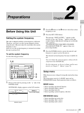
... CH1 CH2 EDIT MODE REC INHI TC VITC 44.1K 01:23:45:15 DISPLAY COUNTER SELECT PLAY F FWD STOP REC LOCAL 9PIN i.LINK MENU HDV DVCAM (DV) ASSIGN RESET(NO) TC PRESET SET(YES) A B 3 2 1 Power on this unit in the unit's memory. SETUP MENU SYSTEM SEL :UC 59.94i(UC...
... CH1 CH2 EDIT MODE REC INHI TC VITC 44.1K 01:23:45:15 DISPLAY COUNTER SELECT PLAY F FWD STOP REC LOCAL 9PIN i.LINK MENU HDV DVCAM (DV) ASSIGN RESET(NO) TC PRESET SET(YES) A B 3 2 1 Power on this unit in the unit's memory. SETUP MENU SYSTEM SEL :UC 59.94i(UC...

Product Manual (HVE-1500A Operating Manuals)
Page 28
...plug - HVR-1500A (this chapter has been discontinued. To view HD video Connect an HD video monitor using a Sony LCD monitor. To view video Make the connections shown in HDV format is down-converted to COMPONENT(HD) (see "Superimposed Text Information" (page 29). When you connect a ... cable, phono plug stereo mini-plug cable Note Video in the following figure. For advice about choosing devices, please contact your Sony dealer or a Sony sales representative. miniplug cable 28 Connecting an External Monitor For details, see page 85). You can connect a video monitor to the...
...plug - HVR-1500A (this chapter has been discontinued. To view HD video Connect an HD video monitor using a Sony LCD monitor. To view video Make the connections shown in HDV format is down-converted to COMPONENT(HD) (see "Superimposed Text Information" (page 29). When you connect a ... cable, phono plug stereo mini-plug cable Note Video in the following figure. For advice about choosing devices, please contact your Sony dealer or a Sony sales representative. miniplug cable 28 Connecting an External Monitor For details, see page 85). You can connect a video monitor to the...
Product Manual (HVE-1500A Operating Manuals)
Page 31
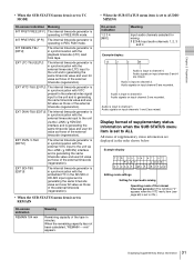
... LTC-T&U [ELTU] The internal timecode generator is in synchronization with the external timecode (LTC) input to the unit via the i.LINK ( HDV/DV) interface and is generating the same timecode value and user bit value as those of the tape in synchronization with the embedded TC in...bit value as those of the external timecode (regeneration). • When the SUB STATUS menu item is set to the unit via the i.LINK ( HDV/DV) interface and is generating the same timecode value and user bit value as those of supplementary status information are mixed. Chapter 2 Preparations • When...
... LTC-T&U [ELTU] The internal timecode generator is in synchronization with the external timecode (LTC) input to the unit via the i.LINK ( HDV/DV) interface and is generating the same timecode value and user bit value as those of the tape in synchronization with the embedded TC in...bit value as those of the external timecode (regeneration). • When the SUB STATUS menu item is set to the unit via the i.LINK ( HDV/DV) interface and is generating the same timecode value and user bit value as those of supplementary status information are mixed. Chapter 2 Preparations • When...
Product Manual (HVE-1500A Operating Manuals)
Page 32
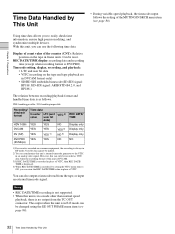
... precision editing, and synchronize multiple devices. YES: handling possible / NO: handling impossible Recording/ playback format Time data Counter LTC (and value user bit data) VITC 2) HDV 1080i YES YES NO DVCAM YES YES YES 3) DV (SP) YES YES 1) NO 4) DVCPRO YES YES NO (25 Mbps) REC DATE/ TIME Display only Display...
... precision editing, and synchronize multiple devices. YES: handling possible / NO: handling impossible Recording/ playback format Time data Counter LTC (and value user bit data) VITC 2) HDV 1080i YES YES NO DVCAM YES YES YES 3) DV (SP) YES YES 1) NO 4) DVCPRO YES YES NO (25 Mbps) REC DATE/ TIME Display only Display...
Product Manual (HVE-1500A Operating Manuals)
Page 33
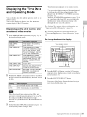
... 720 60p -12 -20 -30 -40 -60 CH1 CH2 EDIT MODE REPEAT TC VITC 48K 01:23:45:15 DISPLAY COUNTER SELECT MENU TC PRESET HDV DVCAM (DV) ASSIGN RESET(NO) SET(YES) PLAY F FWD STOP REC A B 21 Time counter display 1 Press the DISPLAY button to set to ON (factory default...
... 720 60p -12 -20 -30 -40 -60 CH1 CH2 EDIT MODE REPEAT TC VITC 48K 01:23:45:15 DISPLAY COUNTER SELECT MENU TC PRESET HDV DVCAM (DV) ASSIGN RESET(NO) SET(YES) PLAY F FWD STOP REC A B 21 Time counter display 1 Press the DISPLAY button to set to ON (factory default...