Product Manual (HVE-1500A Operating Manuals)
Page 5
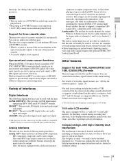
Table of Contents Chapter 1 Overview Features 8 HDV format 8 DVCAM/DV format 8 Variety of interfaces 9 Other features 9 Using the CD-ROM Manual 11 Preparations 11 Reading the CD-ROM Manual 11 Names and ... Data and Operating Mode 33 Displaying on the LCD monitor and an external video monitor ......... 33 Recording Formats and Input/Output Signals 35 Differences among HDV 1080i, DVCAM, and DV formats 35 Input and output signals in E-E mode 35 Playback formats and output signals 38 Usable Cassettes 40 Inserting and ejecting...
Table of Contents Chapter 1 Overview Features 8 HDV format 8 DVCAM/DV format 8 Variety of interfaces 9 Other features 9 Using the CD-ROM Manual 11 Preparations 11 Reading the CD-ROM Manual 11 Names and ... Data and Operating Mode 33 Displaying on the LCD monitor and an external video monitor ......... 33 Recording Formats and Input/Output Signals 35 Differences among HDV 1080i, DVCAM, and DV formats 35 Input and output signals in E-E mode 35 Playback formats and output signals 38 Usable Cassettes 40 Inserting and ejecting...
Product Manual (HVE-1500A Operating Manuals)
Page 6
... 42 Settings for recording 42 Carrying out recording 44 Playback 46 Settings for repeat playback 49 Cuing up to any desired position set as an HDV tape player 63 When using the editing functions of Contents automatic cyclical playback 48 Setting points A and B for playback 46 Playback operations 47 Variable speed... playback - TC Insert Function (DVCAM Format Only 70 6 Table of the recorder 65 Chapter 6 Using the i.LINK Connector for a Linear Editing System 60 Editing in HDV/DVCAM/DV format 67 Rerecording the Timecode -
... 42 Settings for recording 42 Carrying out recording 44 Playback 46 Settings for repeat playback 49 Cuing up to any desired position set as an HDV tape player 63 When using the editing functions of Contents automatic cyclical playback 48 Setting points A and B for playback 46 Playback operations 47 Variable speed... playback - TC Insert Function (DVCAM Format Only 70 6 Table of the recorder 65 Chapter 6 Using the i.LINK Connector for a Linear Editing System 60 Editing in HDV/DVCAM/DV format 67 Rerecording the Timecode -
Product Manual (HVE-1500A Operating Manuals)
Page 8
...Formats and Input/Output Signals" (page 35). High-performance down-conversion function When playing a tape recorded in HDV 1080i format. 1) The HDV and HDV logo are trademarks of Sony Corporation and Victor Company of Japan, Limited (JVC). 2) DVCAM is equipped as standard with an i.LINK interface...the 4:1:1 (60i)/4:2:0 (50i) component digital consumer DV format, DVCAM is 15 µm, 50% wider than the 10 µm of Sony Corporation. When using the HDV 1) and DVCAM 2)/DV formats. It has a 2.7-inch (16:9) color LCD monitor, allowing convenient checking of this unit are digitally ...
...Formats and Input/Output Signals" (page 35). High-performance down-conversion function When playing a tape recorded in HDV 1080i format. 1) The HDV and HDV logo are trademarks of Sony Corporation and Victor Company of Japan, Limited (JVC). 2) DVCAM is equipped as standard with an i.LINK interface...the 4:1:1 (60i)/4:2:0 (50i) component digital consumer DV format, DVCAM is 15 µm, 50% wider than the 10 µm of Sony Corporation. When using the HDV 1) and DVCAM 2)/DV formats. It has a 2.7-inch (16:9) color LCD monitor, allowing convenient checking of this unit are digitally ...
Product Manual (HVE-1500A Operating Manuals)
Page 9
...Analog Input Board enables the unit to the size of switching signal formats, see "Setting the system frequency" (page 25). When in HDV format a downconverted signal can be used as a feeder for example, at broadcasting stations and aboard outside broadcast vans without requiring any option ...playing a tape recorded in 4-channel mode, the two audio channels can be upconverted and output as channels 3 and 4. i.LINK (HDV/DV): This provides i.LINK input/output supporting HDV 1080i and DVCAM/DV formats. Also, the unit is not supported. • A DV (LP) cannot be output either size ...
...Analog Input Board enables the unit to the size of switching signal formats, see "Setting the system frequency" (page 25). When in HDV format a downconverted signal can be used as a feeder for example, at broadcasting stations and aboard outside broadcast vans without requiring any option ...playing a tape recorded in 4-channel mode, the two audio channels can be upconverted and output as channels 3 and 4. i.LINK (HDV/DV): This provides i.LINK input/output supporting HDV 1080i and DVCAM/DV formats. Also, the unit is not supported. • A DV (LP) cannot be output either size ...
Product Manual (HVE-1500A Operating Manuals)
Page 10
...synchronized to 1080i or 720p. Cross-convert function: When HD video signals are input, or when SD video signals are upconverted, or when HDV recorded tapes are each used functions more information about purchasing and installing an option board. 10 Features Remote control The unit can be upconverted...: The three BNC connectors are played back, the HDSDI output signal format can be recorded and played back. Note Consult your Sony dealer or a Sony service representative for SD-SDI input and output or HD-SDI input and output. This unit further supports embedded TC for more rapidly...
...synchronized to 1080i or 720p. Cross-convert function: When HD video signals are input, or when SD video signals are upconverted, or when HDV recorded tapes are each used functions more information about purchasing and installing an option board. 10 Features Remote control The unit can be upconverted...: The three BNC connectors are played back, the HDSDI output signal format can be recorded and played back. Note Consult your Sony dealer or a Sony service representative for SD-SDI input and output or HD-SDI input and output. This unit further supports embedded TC for more rapidly...

Product Manual (HVE-1500A Operating Manuals)
Page 12
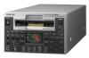
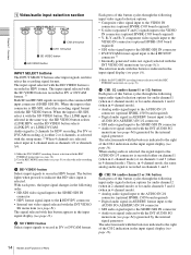
... -40 -60 CH1 CH2 EDIT MODE REPEAT TC VITC 48K 01:23:45:15 DISPLAY COUNTER SELECT PLAY F FWD STOP REC LOCAL 9PIN i.LINK MENU HDV DVCAM (DV) ASSIGN RESET(NO) TC PRESET SET(YES) A B 4 Remote control switch/ indicator section (see page 19) 5 Arrow buttons (see page 16) q; To ... -40 -60 CH1 CH2 EDIT MODE REPEAT TC VITC 48K 01:23:45:15 DISPLAY COUNTER SELECT PLAY F FWD STOP REC LOCAL 9PIN i.LINK MENU HDV DVCAM (DV) ASSIGN RESET(NO) TC PRESET SET(YES) A B 7 EJECT button 8 RESET (NO) button 9 SET (YES) button 5 CONTROL-S connector 3 LCD monitor (see page 19) a...
... -40 -60 CH1 CH2 EDIT MODE REPEAT TC VITC 48K 01:23:45:15 DISPLAY COUNTER SELECT PLAY F FWD STOP REC LOCAL 9PIN i.LINK MENU HDV DVCAM (DV) ASSIGN RESET(NO) TC PRESET SET(YES) A B 4 Remote control switch/ indicator section (see page 19) 5 Arrow buttons (see page 16) q; To ... -40 -60 CH1 CH2 EDIT MODE REPEAT TC VITC 48K 01:23:45:15 DISPLAY COUNTER SELECT PLAY F FWD STOP REC LOCAL 9PIN i.LINK MENU HDV DVCAM (DV) ASSIGN RESET(NO) TC PRESET SET(YES) A B 7 EJECT button 8 RESET (NO) button 9 SET (YES) button 5 CONTROL-S connector 3 LCD monitor (see page 19) a...
Product Manual (HVE-1500A Operating Manuals)
Page 13
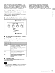
... bits) t CNT... 1) 1) When the TC SELECT menu item is set to 9PIN or i.LINK, and an external device is connected to the REMOTE connector or HDV/DV connector on the rear panel, then it . g EJECT button When you can assign a desired menu item (level 1 or level 2) to use the menu, ... fullscreen Note When the DOWN CONVERTER >CONV MODE is set to EDGE-CROP, the LCD monitor screen is only possible to zero. f Cassette compartment Accepts HDV, DVCAM, DV and DVCPRO (25 Mbps) videocassettes. i SET (YES) button Press this buton to select the type of the time counter) t VITC ( VITC timecode) t ...
... bits) t CNT... 1) 1) When the TC SELECT menu item is set to 9PIN or i.LINK, and an external device is connected to the REMOTE connector or HDV/DV connector on the rear panel, then it . g EJECT button When you can assign a desired menu item (level 1 or level 2) to use the menu, ... fullscreen Note When the DOWN CONVERTER >CONV MODE is set to EDGE-CROP, the LCD monitor screen is only possible to zero. f Cassette compartment Accepts HDV, DVCAM, DV and DVCPRO (25 Mbps) videocassettes. i SET (YES) button Press this buton to select the type of the time counter) t VITC ( VITC timecode) t ...
Product Manual (HVE-1500A Operating Manuals)
Page 14
...pressed to indicate that HD video input is recorded in DV or DVCAM format. 1) Both SD and HD SDI signals are selected, select input in HDV format. Each press of this button cycles through the following input video signal selection options. • Composite video signal input to the VIDEO IN ...input to the common SDI input connector (SD/HD SDI IN). The input signal selected with the setup menu. 2) When 4 channels are input to the HDV/DV connector 1) • Internally generated video test signal (selected with the INT VIDEO SG menu item (see page 81)) The selection made with this ...
...pressed to indicate that HD video input is recorded in DV or DVCAM format. 1) Both SD and HD SDI signals are selected, select input in HDV format. Each press of this button cycles through the following input video signal selection options. • Composite video signal input to the VIDEO IN ...input to the common SDI input connector (SD/HD SDI IN). The input signal selected with the setup menu. 2) When 4 channels are input to the HDV/DV connector 1) • Internally generated video test signal (selected with the INT VIDEO SG menu item (see page 81)) The selection made with this ...
Product Manual (HVE-1500A Operating Manuals)
Page 15
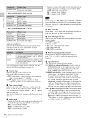
...signal levels cannot be adjusted with the LEVEL SELECT menu item (see page 83). Notes • When selecting an i.LINK (HDV) input to record signals in HDV format, it is possible to adjust the audio levels on the two channels separately. channel mode) or on the setting of... REC MODE menu item (see page 84). b VARIABLE switch Use to control audio levels function differently depending on channels 2 and 4 (when in HDV format to the DVCAM/DV format using the i.LINK output, the adjustments of Parts However, when converting a tape recorded in 4-channel mode). The ...
...signal levels cannot be adjusted with the LEVEL SELECT menu item (see page 83). Notes • When selecting an i.LINK (HDV) input to record signals in HDV format, it is possible to adjust the audio levels on the two channels separately. channel mode) or on the setting of... REC MODE menu item (see page 84). b VARIABLE switch Use to control audio levels function differently depending on channels 2 and 4 (when in HDV format to the DVCAM/DV format using the i.LINK output, the adjustments of Parts However, when converting a tape recorded in 4-channel mode). The ...

Product Manual (HVE-1500A Operating Manuals)
Page 17
... is installed in the unit. • When HD VIDEO input is selected Video area display SG:HD HD SDI i.LINK:HDV Signal format HD test signal HD-SDI video signal 1) i.LINK compatible HDV format video/ audio signal 1) Downconverted signals (analog video output) are output from the VIDEO OUT connectors. • When SD...
... is installed in the unit. • When HD VIDEO input is selected Video area display SG:HD HD SDI i.LINK:HDV Signal format HD test signal HD-SDI video signal 1) i.LINK compatible HDV format video/ audio signal 1) Downconverted signals (analog video output) are output from the VIDEO OUT connectors. • When SD...
Product Manual (HVE-1500A Operating Manuals)
Page 18
... 1/2 CH 3/4 Functions Channel 1 is output from the AUDIO OUT 1/ 3 connector, and channel 2 from the AUDIO OUT 2/4 connector. However, only up to the HDV/DV connector on this unit. EDIT MODE: Lights when this unit does not coincide with that contains a recording in the time counter display. Channel 3 is ... can be played back on the rear panel (see page 85). This unit can be used to DVCAM. 18 Names and Functions of i.LINK (HDV) input, 1080/60i or 1080/50i format 4-channel mode audio is recorded without change the output channel selection with the AUDIO OUTPUT menu item (see...
... 1/2 CH 3/4 Functions Channel 1 is output from the AUDIO OUT 1/ 3 connector, and channel 2 from the AUDIO OUT 2/4 connector. However, only up to the HDV/DV connector on this unit. EDIT MODE: Lights when this unit does not coincide with that contains a recording in the time counter display. Channel 3 is ... can be played back on the rear panel (see page 85). This unit can be used to DVCAM. 18 Names and Functions of i.LINK (HDV) input, 1080/60i or 1080/50i format 4-channel mode audio is recorded without change the output channel selection with the AUDIO OUTPUT menu item (see...
Product Manual (HVE-1500A Operating Manuals)
Page 19
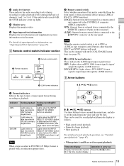
...and STOP buttons will work. c i.LINK format indicators These indicate the i.LINK input/output signal format. HDV DVCAM (DV) 5 Arrow buttons 3 i.LINK format indicators M, m, HDV: Lights when an HDV 1080i format signal is input/output through the i.LINK interface. This can be changed with the LOCAL ENABLE... Lights when a DVCAM/DV format signal is input/ output through the i.LINK interface. For details of channels 1 and 2 or 1 to the HDV/DV connector on the rear panel. Note When the remote control switch is controlled from the front panel, or from an external device connected to...
...and STOP buttons will work. c i.LINK format indicators These indicate the i.LINK input/output signal format. HDV DVCAM (DV) 5 Arrow buttons 3 i.LINK format indicators M, m, HDV: Lights when an HDV 1080i format signal is input/output through the i.LINK interface. This can be changed with the LOCAL ENABLE... Lights when a DVCAM/DV format signal is input/ output through the i.LINK interface. For details of channels 1 and 2 or 1 to the HDV/DV connector on the rear panel. Note When the remote control switch is controlled from the front panel, or from an external device connected to...
Product Manual (HVE-1500A Operating Manuals)
Page 21
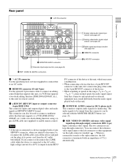
...external equipment may sound differently from this connector can connect the reference video signal input to the left connector is terminated with a 6-pin HDV/DV connector, when you connect or disconnect the i.LINK cable while the device is connected to the AC outlet, high-voltage current (8...IN(SD/HD) SDI OUT1 OUT2 SDI OUT1 OUT2 HD SDI 1/3 2/4 IN AUDIO I/O (AES/EBU) OUT TC IN OUT MONITOR AUDIO 1/2 3/4 1/2 3/4 HDV/DV REMOTE 4 MONITOR AUDIO connector 4 Timecode input/output section (see page 12). b REMOTE connector (D-sub 9-pin) Use the optional 9-pin remote cable to connect...
...external equipment may sound differently from this connector can connect the reference video signal input to the left connector is terminated with a 6-pin HDV/DV connector, when you connect or disconnect the i.LINK cable while the device is connected to the AC outlet, high-voltage current (8...IN(SD/HD) SDI OUT1 OUT2 SDI OUT1 OUT2 HD SDI 1/3 2/4 IN AUDIO I/O (AES/EBU) OUT TC IN OUT MONITOR AUDIO 1/2 3/4 1/2 3/4 HDV/DV REMOTE 4 MONITOR AUDIO connector 4 Timecode input/output section (see page 12). b REMOTE connector (D-sub 9-pin) Use the optional 9-pin remote cable to connect...
Product Manual (HVE-1500A Operating Manuals)
Page 22
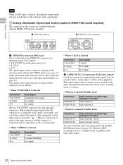
... to these connectors depend on which input signals are the following VIDEO IN connectors for example, you can be input to other audio equipment. However, HDV recording is selected Connectors Y/S-Y/CPST R-Y/S-C B-Y Input signal Composite video signal not usable not usable The two Y/S-Y/CPST connectors are loop-through connectors) • R-Y/S-C • B-Y The...
... to these connectors depend on which input signals are the following VIDEO IN connectors for example, you can be input to other audio equipment. However, HDV recording is selected Connectors Y/S-Y/CPST R-Y/S-C B-Y Input signal Composite video signal not usable not usable The two Y/S-Y/CPST connectors are loop-through connectors) • R-Y/S-C • B-Y The...

Product Manual (HVE-1500A Operating Manuals)
Page 23
... is selected) Audio channel 2 (when 1/2 CH is selected) or silent (when 3/4 CH is selected) • In 4-channel (32 kHz) mode Audio is 2-channel mode during HDV tape playback.
... is selected) Audio channel 2 (when 1/2 CH is selected) or silent (when 3/4 CH is selected) • In 4-channel (32 kHz) mode Audio is 2-channel mode during HDV tape playback.
Product Manual (HVE-1500A Operating Manuals)
Page 25
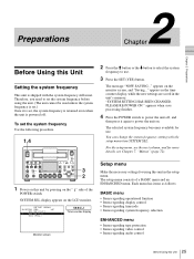
... CH1 CH2 EDIT MODE REC INHI TC VITC 44.1K 01:23:45:15 DISPLAY COUNTER SELECT PLAY F FWD STOP REC LOCAL 9PIN i.LINK MENU HDV DVCAM (DV) ASSIGN RESET(NO) TC PRESET SET(YES) A B 3 2 1 Power on this unit by pressing on the monitor screen, and "Saving..." appears in the time...
... CH1 CH2 EDIT MODE REC INHI TC VITC 44.1K 01:23:45:15 DISPLAY COUNTER SELECT PLAY F FWD STOP REC LOCAL 9PIN i.LINK MENU HDV DVCAM (DV) ASSIGN RESET(NO) TC PRESET SET(YES) A B 3 2 1 Power on this unit by pressing on the monitor screen, and "Saving..." appears in the time...

Product Manual (HVE-1500A Operating Manuals)
Page 28
...SD/HD) SDI OUT1 OUT2 SDI OUT1 OUT2 HD SDI 1/3 2/4 IN AUDIO I /O (AES/EBU) OUT TC IN OUT MONITOR AUDIO 1/2 3/4 1/2 3/4 HDV/DV REMOTE MONITOR AUDIO (SUPER) CPST Connection method and cables Connection method Connection cables (not supplied) Composite ((SUPER) CPST) Audio (MONITOR AUDIO) 75 Ω... menu item to an SD signal. For advice about choosing devices, please contact your Sony dealer or a Sony sales representative. To view HD video Connect an HD video monitor using a Sony LCD monitor. You can also superimpose character information such as timecode and the unit's ...
...SD/HD) SDI OUT1 OUT2 SDI OUT1 OUT2 HD SDI 1/3 2/4 IN AUDIO I /O (AES/EBU) OUT TC IN OUT MONITOR AUDIO 1/2 3/4 1/2 3/4 HDV/DV REMOTE MONITOR AUDIO (SUPER) CPST Connection method and cables Connection method Connection cables (not supplied) Composite ((SUPER) CPST) Audio (MONITOR AUDIO) 75 Ω... menu item to an SD signal. For advice about choosing devices, please contact your Sony dealer or a Sony sales representative. To view HD video Connect an HD video monitor using a Sony LCD monitor. You can also superimpose character information such as timecode and the unit's ...
Product Manual (HVE-1500A Operating Manuals)
Page 31
...value as those of the external timecode (regeneration). • When the SUB STATUS menu item is set to the unit via the i.LINK ( HDV/DV) interface and is generating the same timecode value and user bit value as those of the external timecode (regeneration). EXT SDI-T&U [ESTU]... "REMAIN --- Audio signals on input channel 2 are displayed in synchronization with the external timecode (LTC) input to the unit via the i.LINK ( HDV/DV) interface and is generating the same timecode value and user bit value as those of the external timecode (regeneration). EXT VITC-T&U [EVTU] The ...
...value as those of the external timecode (regeneration). • When the SUB STATUS menu item is set to the unit via the i.LINK ( HDV/DV) interface and is generating the same timecode value and user bit value as those of the external timecode (regeneration). EXT SDI-T&U [ESTU]... "REMAIN --- Audio signals on input channel 2 are displayed in synchronization with the external timecode (LTC) input to the unit via the i.LINK ( HDV/DV) interface and is generating the same timecode value and user bit value as those of the external timecode (regeneration). EXT VITC-T&U [EVTU] The ...
Product Manual (HVE-1500A Operating Manuals)
Page 32
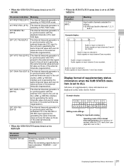
..., the recording is in DF mode. YES: handling possible / NO: handling impossible Recording/ playback format Time data Counter LTC (and value user bit data) VITC 2) HDV 1080i YES YES NO DVCAM YES YES YES 3) DV (SP) YES YES 1) NO 4) DVCPRO YES YES NO (25 Mbps) REC DATE/ TIME Display only Display...
..., the recording is in DF mode. YES: handling possible / NO: handling impossible Recording/ playback format Time data Counter LTC (and value user bit data) VITC 2) HDV 1080i YES YES NO DVCAM YES YES YES 3) DV (SP) YES YES 1) NO 4) DVCPRO YES YES NO (25 Mbps) REC DATE/ TIME Display only Display...
Product Manual (HVE-1500A Operating Manuals)
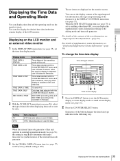
Page 33
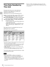
... 720 60p -12 -20 -30 -40 -60 CH1 CH2 EDIT MODE REPEAT TC VITC 48K 01:23:45:15 DISPLAY COUNTER SELECT MENU TC PRESET HDV DVCAM (DV) ASSIGN RESET(NO) SET(YES) PLAY F FWD STOP REC A B 21 Time counter display 1 Press the DISPLAY button to set to status display mode...
... 720 60p -12 -20 -30 -40 -60 CH1 CH2 EDIT MODE REPEAT TC VITC 48K 01:23:45:15 DISPLAY COUNTER SELECT MENU TC PRESET HDV DVCAM (DV) ASSIGN RESET(NO) SET(YES) PLAY F FWD STOP REC A B 21 Time counter display 1 Press the DISPLAY button to set to status display mode...