
Service Manual
Page 2
REPLACE THESE COMPONENTS WITH SONY PARTS WHOSE PART NUMBERS APPEAR AS SHOWN IN THIS MANUAL OR IN SUPPLEMENTS PUBLISHED BY SONY. 2 HCD-ZUX9 Ver. 1.1 Tape deck section Recording system 4-track 2-channel stereo Frequency response 50 - 13,000 Hz (±3 dB), using Sony TYPE I tape Tuner section FM stereo, FM/AM superheterodyne tuner FM tuner section Tuning range US.... • Abbreviation AUS : Australian model SAFETY-RELATED COMPONENT WARNING!! COMPONENTS IDENTIFIED BY MARK 0 OR DOTTED LINE WITH MARK 0 ON THE SCHEMATIC DIAGRAMS AND IN THE PARTS LIST ARE CRITICAL TO SAFE OPERATION.
REPLACE THESE COMPONENTS WITH SONY PARTS WHOSE PART NUMBERS APPEAR AS SHOWN IN THIS MANUAL OR IN SUPPLEMENTS PUBLISHED BY SONY. 2 HCD-ZUX9 Ver. 1.1 Tape deck section Recording system 4-track 2-channel stereo Frequency response 50 - 13,000 Hz (±3 dB), using Sony TYPE I tape Tuner section FM stereo, FM/AM superheterodyne tuner FM tuner section Tuning range US.... • Abbreviation AUS : Australian model SAFETY-RELATED COMPONENT WARNING!! COMPONENTS IDENTIFIED BY MARK 0 OR DOTTED LINE WITH MARK 0 ON THE SCHEMATIC DIAGRAMS AND IN THE PARTS LIST ARE CRITICAL TO SAFE OPERATION.

Service Manual
Page 3
... TEST The AC leakage from any exposed metal part to chassis, must have a 2V AC range are examples of a passive VOM that is applied for Class 1. Measuring the voltage drop across a resistor by the objective lens in hazardous radiation exposure. A. HCD-ZUX9 Ver. 1.1 Notes on chip component replacement &#... leadfree mark (LF) indicating the solder contains no lead. (Caution: Some printed circuit boards may also be measured by any exposed metal part having a return to earth ground and from the objective lens. Caution: The printed pattern (copper foil) may result in the optical pickup...
... TEST The AC leakage from any exposed metal part to chassis, must have a 2V AC range are examples of a passive VOM that is applied for Class 1. Measuring the voltage drop across a resistor by the objective lens in hazardous radiation exposure. A. HCD-ZUX9 Ver. 1.1 Notes on chip component replacement &#... leadfree mark (LF) indicating the solder contains no lead. (Caution: Some printed circuit boards may also be measured by any exposed metal part having a return to earth ground and from the objective lens. Caution: The printed pattern (copper foil) may result in the optical pickup...

Service Manual
Page 4
E2 E51 E13 AUS US Model Part No. 3-095-364-0s 3-095-364-1s 3-095-364-2s 3-095-364-5s 3-095-364-6s • Abbreviation E2 : 120 V AC area in E model E13 : ... to Lead-out regarded as a single session. 4 PART No. MP3 audio tracks must be in and end at a disc control area called the Lead-in MPEG 1 Audio Layer 3 format. 2) A logical format of data using the Track-At-Once method. Conventional discs begin at an area called Lead-out. HCD-ZUX9 Ver. 1.1 MODEL IDENTIFICATION -
E2 E51 E13 AUS US Model Part No. 3-095-364-0s 3-095-364-1s 3-095-364-2s 3-095-364-5s 3-095-364-6s • Abbreviation E2 : 120 V AC area in E model E13 : ... to Lead-out regarded as a single session. 4 PART No. MP3 audio tracks must be in and end at a disc control area called the Lead-in MPEG 1 Audio Layer 3 format. 2) A logical format of data using the Track-At-Once method. Conventional discs begin at an area called Lead-out. HCD-ZUX9 Ver. 1.1 MODEL IDENTIFICATION -

Service Manual
Page 5
.... Printed Wiring Board - Printed Wiring Boards - Key Section 64 7-30. LED Section (2/2 66 7-32. Power Section 69 8. GENERAL Guide to Parts and Controls 7 3. Top Case Section 16 3-3. Main Board 20 3-10. Center Key Board, Beat Creator Board, X-Round Board 22 3-15. ...Diagram - Printed Wiring Board - Power AMP Section 58 7-24. FL Section 61 7-27. Printed Wiring Boards - LED Section (1/2 65 7-31. HCD-ZUX9 TABLE OF CONTENTS 1. Loading Panel 17 3-5. Sensor Board 25 3-21. TEST MODE 27 5. Block Diagram - Tape/Tuner Section 36 7-3. Effector Section ...
.... Printed Wiring Board - Printed Wiring Boards - Key Section 64 7-30. LED Section (2/2 66 7-32. Power Section 69 8. GENERAL Guide to Parts and Controls 7 3. Top Case Section 16 3-3. Main Board 20 3-10. Center Key Board, Beat Creator Board, X-Round Board 22 3-15. ...Diagram - Printed Wiring Board - Power AMP Section 58 7-24. FL Section 61 7-27. Printed Wiring Boards - LED Section (1/2 65 7-31. HCD-ZUX9 TABLE OF CONTENTS 1. Loading Panel 17 3-5. Sensor Board 25 3-21. TEST MODE 27 5. Block Diagram - Tape/Tuner Section 36 7-3. Effector Section ...
Service Manual
Page 7
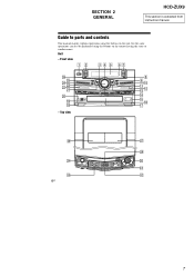
SECTION 2 GENERAL HCD-ZUX9 This section is extracted from instruction manual. Top view 8 9 q; ql qk - ea ed es 6GB 7 Front view 12 3 4 5 67 wh wg wf wd ws wa w; Guide to parts and controls This manual mainly explains operations using the buttons on the unit, but the same operations can also be performed using the buttons on the remote having the same or similar names. Unit - qa qs qd qf qg qh qj wk wj wl ef e;
SECTION 2 GENERAL HCD-ZUX9 This section is extracted from instruction manual. Top view 8 9 q; ql qk - ea ed es 6GB 7 Front view 12 3 4 5 67 wh wg wf wd ws wa w; Guide to parts and controls This manual mainly explains operations using the buttons on the unit, but the same operations can also be performed using the buttons on the remote having the same or similar names. Unit - qa qs qd qf qg qh qj wk wj wl ef e;
Service Manual
Page 31
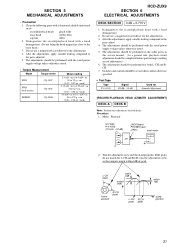
...After the adjustments, apply suitable locking compound to the parts adjusted. 5. Switches and controls should be performed with a head demagnetizer. (Do not bring the head magnetizer close to 170 g • cm (0.68 - 2.36 oz • inch) HCD-ZUX9 SECTION 6 ELECTRICAL ADJUSTMENTS DECK SECTION 0 dB =... in the order given in this adjustments for both decks Procedure: 1. After the adjustments, apply suitable locking compound to the parts adjust. 4. Demagnetize the record/playback head with the rated power supply voltage unless otherwise noted. 5. The adjustments should be ...
...After the adjustments, apply suitable locking compound to the parts adjusted. 5. Switches and controls should be performed with a head demagnetizer. (Do not bring the head magnetizer close to 170 g • cm (0.68 - 2.36 oz • inch) HCD-ZUX9 SECTION 6 ELECTRICAL ADJUSTMENTS DECK SECTION 0 dB =... in the order given in this adjustments for both decks Procedure: 1. After the adjustments, apply suitable locking compound to the parts adjust. 4. Demagnetize the record/playback head with the rated power supply voltage unless otherwise noted. 5. The adjustments should be ...

Service Manual
Page 33
...1 TP106 (FE) 26 25 33 Use an oscilloscope with the following test disc on test mode. • CD: YEDS-18 (PART No. 3-702-101-01) or PATD-012 (PART No. 4-225-203-01) Note: 1. Connect an oscilloscope to obtain best waveform. RFMON signal waveform VOLT/DIV: 200 mV TIME/DIV...;" can be clearly distinguished at the center of open and close the disc tray, actuate the focus search). 4. Therefore, check each item in order given. 2. HCD-ZUX9 CD SECTION [TEST DISC LIST] Use the following checks. [S-CURVE CHECK] BD91 board TP106 (FE) TP124 (VC) oscilloscope + - [RF LEVEL CHECK] BD91 board...
...1 TP106 (FE) 26 25 33 Use an oscilloscope with the following test disc on test mode. • CD: YEDS-18 (PART No. 3-702-101-01) or PATD-012 (PART No. 4-225-203-01) Note: 1. Connect an oscilloscope to obtain best waveform. RFMON signal waveform VOLT/DIV: 200 mV TIME/DIV...;" can be clearly distinguished at the center of open and close the disc tray, actuate the focus search). 4. Therefore, check each item in order given. 2. HCD-ZUX9 CD SECTION [TEST DISC LIST] Use the following checks. [S-CURVE CHECK] BD91 board TP106 (FE) TP124 (VC) oscilloscope + - [RF LEVEL CHECK] BD91 board...

Service Manual
Page 42
... variations may not come printed with a oscilloscope. No. No. GS Q BCE These are indicated. HCD-ZUX9 • Note for Printed Wiring Boards and Schematic Diagrams Note on Printed Wiring Board: • X : parts extracted from the component side. • Y : parts extracted from the conductor side. • : Pattern from the side which enables seeing. (The other...
... variations may not come printed with a oscilloscope. No. No. GS Q BCE These are indicated. HCD-ZUX9 • Note for Printed Wiring Boards and Schematic Diagrams Note on Printed Wiring Board: • X : parts extracted from the component side. • Y : parts extracted from the conductor side. • : Pattern from the side which enables seeing. (The other...

Service Manual
Page 87
...-3 Remark 87 MAIN SECTION #1 top case section 5 2 not supplied #1 (PRIMARY board) 1 #1 HCD-ZUX9 Ver. 1.1 The components identified by mark 0 or dotted line with mark 0 are critical for routine service. back panel section #1 #1 #1 #1 #1 #1 #1 #1 2 chassis section 3 1 front panel section (1) 4 #2 Ref. Replace only with part number specified. Description 3-363-099-02 SCREW (CASE 3 TP2) 3-363-099...
...-3 Remark 87 MAIN SECTION #1 top case section 5 2 not supplied #1 (PRIMARY board) 1 #1 HCD-ZUX9 Ver. 1.1 The components identified by mark 0 or dotted line with mark 0 are critical for routine service. back panel section #1 #1 #1 #1 #1 #1 #1 #1 2 chassis section 3 1 front panel section (1) 4 #2 Ref. Replace only with part number specified. Description 3-363-099-02 SCREW (CASE 3 TP2) 3-363-099...

Service Manual
Page 88
FRONT PANEL SECTION (1) not supplied (POWER LED board) 52 51 52 52 not supplied (CENTER L LED board) 52 not supplied 52 not supplied 52 not supplied (LEFT KEY board) 52 53 52 FL900 52 not supplied (RIGHT KEY board) 52 front panel section (2) 52 not supplied (CENTER R LED board) Ref. Description 1-828-991-11 WIRE (FLAT TYPE) (17 CORE) 1-519-955-11 VACUUM FLUORESCENT DISPLAY Remark Description A-1257-600-A FL BOARD, COMPLETE 3-087-053-01 +BVTP 2.6 (3CR) 88 Remark Ref. HCD-ZUX9 8-2. No. 53 FL900 Part No. No. 51 52 Part No.
FRONT PANEL SECTION (1) not supplied (POWER LED board) 52 51 52 52 not supplied (CENTER L LED board) 52 not supplied 52 not supplied 52 not supplied (LEFT KEY board) 52 53 52 FL900 52 not supplied (RIGHT KEY board) 52 front panel section (2) 52 not supplied (CENTER R LED board) Ref. Description 1-828-991-11 WIRE (FLAT TYPE) (17 CORE) 1-519-955-11 VACUUM FLUORESCENT DISPLAY Remark Description A-1257-600-A FL BOARD, COMPLETE 3-087-053-01 +BVTP 2.6 (3CR) 88 Remark Ref. HCD-ZUX9 8-2. No. 53 FL900 Part No. No. 51 52 Part No.

Service Manual
Page 90
...) 4-225-252-21 CUSHION (FOOT) X-2177-349-1 FRONT PANEL ASSY (CD) (E2,E13,E51) Ref. No. 155 155 156 157 158 Part No. No. 151 152 153 153 154 155 Part No. FRONT PANEL SECTION (3) not supplied (BEAT CREATOR board) 158 supplied with S950 156 157 155 151 151 152 151 not...) (AUS) X-2187-306-1 FRONT PANEL ASSY (CD-U2) (US) 3-095-313-01 KNOB (VOLUME) 3-095-315-01 BRACKET (JOG) 3-095-314-01 KNOB (JOG) 90 HCD-ZUX9 Ver. 1.1 8-4.
...) 4-225-252-21 CUSHION (FOOT) X-2177-349-1 FRONT PANEL ASSY (CD) (E2,E13,E51) Ref. No. 155 155 156 157 158 Part No. No. 151 152 153 153 154 155 Part No. FRONT PANEL SECTION (3) not supplied (BEAT CREATOR board) 158 supplied with S950 156 157 155 151 151 152 151 not...) (AUS) X-2187-306-1 FRONT PANEL ASSY (CD-U2) (US) 3-095-313-01 KNOB (VOLUME) 3-095-315-01 BRACKET (JOG) 3-095-314-01 KNOB (JOG) 90 HCD-ZUX9 Ver. 1.1 8-4.

Service Manual
Page 91
No. 209 210 211 212 213 Part No. TOP CASE SECTION HCD-ZUX9 Ver. 1.1 not supplied 201 204 202 202 206 213 213 216 214 206 213 215 203 209 not supplied 213 205 213 207 208 not ...-352-01 STOPPER (PLAY-A) 215 4-231-836-01 SPRING (HEART CAM-A) 216 4-231-824-01 CAM (A), HEART Remark 91 No. 201 202 203 204 205 Part No. 8-5. Description 3-095-348-01 HOLDER (TC-L) 2-669-613-01 SPRING, DETENT 3-211-052-01 SPRING (A) 3-095-349-01 HOLDER (TC-R) 3-211-053-01 SPRING...
No. 209 210 211 212 213 Part No. TOP CASE SECTION HCD-ZUX9 Ver. 1.1 not supplied 201 204 202 202 206 213 213 216 214 206 213 215 203 209 not supplied 213 205 213 207 208 not ...-352-01 STOPPER (PLAY-A) 215 4-231-836-01 SPRING (HEART CAM-A) 216 4-231-824-01 CAM (A), HEART Remark 91 No. 201 202 203 204 205 Part No. 8-5. Description 3-095-348-01 HOLDER (TC-L) 2-669-613-01 SPRING, DETENT 3-211-052-01 SPRING (A) 3-095-349-01 HOLDER (TC-R) 3-211-053-01 SPRING...

Service Manual
Page 92
... (FM/AM) (ANTENNA) (AUS) TUNER (FM/AM) (ANTENNA) (E2,E13,E51) SCREW +BVTP 3X8 TYPE2 IT-3 SCREW +BVTT 2.6X6 (S) SCREW +BVTP 3X12 TYPE2 IT-3 92 HCD-ZUX9 Ver. 1.1 8-6. BACK PANEL SECTION 251 #1 not supplied M891 252 not supplied (EFFECTOR board) not supplied #4 #3 #1 253 TU901 Ref. Description 1-468-737-51 1-828-361-11..., POWER WIRE (FLAT TYPE) (19 CORE) WIRE (FLAT TYPE) (9 CORE) FAN, DC TUNER (FM/AM) (ANTENNA) (US) Remark Ref. No. 0 251 252 253 M891 TU901 Part No. TU901 TU901...
... (FM/AM) (ANTENNA) (AUS) TUNER (FM/AM) (ANTENNA) (E2,E13,E51) SCREW +BVTP 3X8 TYPE2 IT-3 SCREW +BVTT 2.6X6 (S) SCREW +BVTP 3X12 TYPE2 IT-3 92 HCD-ZUX9 Ver. 1.1 8-6. BACK PANEL SECTION 251 #1 not supplied M891 252 not supplied (EFFECTOR board) not supplied #4 #3 #1 253 TU901 Ref. Description 1-468-737-51 1-828-361-11..., POWER WIRE (FLAT TYPE) (19 CORE) WIRE (FLAT TYPE) (9 CORE) FAN, DC TUNER (FM/AM) (ANTENNA) (US) Remark Ref. No. 0 251 252 253 M891 TU901 Part No. TU901 TU901...

Service Manual
Page 93
... No. 301 301 302 303 0 304 0 304 0 304 0 305 306 307 308 309 310 310 310 310 310 311 312 313 314 0 F1241 0 F1241 Part No. Description Remark A-1257-724-A TRANS BOARD, COMPLETE (EXCEPT US) A-1392-675-A TRANS BOARD, COMPLETE (US) 4-900-386-01 SCREW 3-703-244-21 BUSHING ... (TIME LAG) (T8AL/250V) (EXCEPT US) Ref. No. 0 F1251 0 F1251 0 F1261 0 F1261 0 F1271 0 F1271 0 F1281 0 F1281 0 F1291 0 F1291 M892 0 T1200 0 T1200 #1 #2 #4 Part No. HCD-ZUX9 Ver. 1.1 8-7. Description Remark 1-533-311-12 1-533-949-33 1-533-311-12 1-533-949-33 1-533-311-12 FUSE, GLASS CYLINDRICAL (DIA.5) (8A/125V) (US...
... No. 301 301 302 303 0 304 0 304 0 304 0 305 306 307 308 309 310 310 310 310 310 311 312 313 314 0 F1241 0 F1241 Part No. Description Remark A-1257-724-A TRANS BOARD, COMPLETE (EXCEPT US) A-1392-675-A TRANS BOARD, COMPLETE (US) 4-900-386-01 SCREW 3-703-244-21 BUSHING ... (TIME LAG) (T8AL/250V) (EXCEPT US) Ref. No. 0 F1251 0 F1251 0 F1261 0 F1261 0 F1271 0 F1271 0 F1281 0 F1281 0 F1291 0 F1291 M892 0 T1200 0 T1200 #1 #2 #4 Part No. HCD-ZUX9 Ver. 1.1 8-7. Description Remark 1-533-311-12 1-533-949-33 1-533-311-12 1-533-949-33 1-533-311-12 FUSE, GLASS CYLINDRICAL (DIA.5) (8A/125V) (US...

Service Manual
Page 94
...-01 PULLEY (TABLE) 3-231-598-01 SHEET (BA) A-1108-965-A MOTOR ASSY, TABLE (TABLE) 94 No. 360 361 362 363 364 Part No. No. 351 352 353 354 355 Part No. HCD-ZUX9 8-8. CD MECHANISM SECTION (1) (CDM74KF-K6BD91UR-WOD) 356 362 358 351 357 356 355 356 357 355 359 358 361 364 360...
...-01 PULLEY (TABLE) 3-231-598-01 SHEET (BA) A-1108-965-A MOTOR ASSY, TABLE (TABLE) 94 No. 360 361 362 363 364 Part No. No. 351 352 353 354 355 Part No. HCD-ZUX9 8-8. CD MECHANISM SECTION (1) (CDM74KF-K6BD91UR-WOD) 356 362 358 351 357 356 355 356 357 355 359 358 361 364 360...

Service Manual
Page 95
No. 401 402 403 404 405 Part No. No. 417 418 419 420 421 Part No. Description 4-224-611-01 4-224-606-01 4-243-818-01 4-243-822-02 4-243-817-22 GEAR (LOADING B) GEAR (RV) GEAR (U/D) LEVER (LIFTER) CHASSIS ... TYPE) (13 CORE) 4-218-253-42 SCREW (M2.6), +BTTP 1-834-268-11 WIRE (FLAT TYPE) (16 CORE) Remark Ref. CD MECHANISM SECTION (2) (CDM74KF-K6BD91UR-WOD) HCD-ZUX9 415 414 416 417 419 408 408 408 420 413 418 RE701 421 422 423 404 412 M751 411 409 408 407 401 410 404...
No. 401 402 403 404 405 Part No. No. 417 418 419 420 421 Part No. Description 4-224-611-01 4-224-606-01 4-243-818-01 4-243-822-02 4-243-817-22 GEAR (LOADING B) GEAR (RV) GEAR (U/D) LEVER (LIFTER) CHASSIS ... TYPE) (13 CORE) 4-218-253-42 SCREW (M2.6), +BTTP 1-834-268-11 WIRE (FLAT TYPE) (16 CORE) Remark Ref. CD MECHANISM SECTION (2) (CDM74KF-K6BD91UR-WOD) HCD-ZUX9 415 414 416 417 419 408 408 408 420 413 418 RE701 421 422 423 404 412 M751 411 409 408 407 401 410 404...

Service Manual
Page 96
...220-230 V AC area in ohms. METAL: Metal-film resistor. D1030 D1031 D1032 D1033 D1034 D1035 Part No. D923 D924 D925 D926 D927 Part No. When indicating parts by mark 0 or dotted line with part number specified. Description BASE L LED BOARD Remark < DIODE > 6-501-872-01 LED SLI-560DTT32X-... CHIP ELECT CHIP CERAMIC CHIP CERAMIC CHIP 0.1uF 100uF 0.1uF 0.1uF 16V 20% 10V 16V 16V 96 HCD-ZUX9 BASE L LED BASE R LED BD91 NOTE: • Due to standardization, replacements in the parts list may be anticipated when ordering these items. • SEMICONDUCTORS In each case, u : µ, ...
...220-230 V AC area in ohms. METAL: Metal-film resistor. D1030 D1031 D1032 D1033 D1034 D1035 Part No. D923 D924 D925 D926 D927 Part No. When indicating parts by mark 0 or dotted line with part number specified. Description BASE L LED BOARD Remark < DIODE > 6-501-872-01 LED SLI-560DTT32X-... CHIP ELECT CHIP CERAMIC CHIP CERAMIC CHIP 0.1uF 100uF 0.1uF 0.1uF 16V 20% 10V 16V 16V 96 HCD-ZUX9 BASE L LED BASE R LED BD91 NOTE: • Due to standardization, replacements in the parts list may be anticipated when ordering these items. • SEMICONDUCTORS In each case, u : µ, ...

Service Manual
Page 98
Part No. No. No. Part No. Description R212 R213 R214 R216 R218 1-216-809-11 1-216-809-11 1-216-809-11 1-216-809-11 1-216-845-11 METAL CHIP METAL ... R925 1-216-821-11 METAL CHIP 1K 5% 1/10W R979 1-216-821-11 METAL CHIP 1K 5% 1/10W R980 1-216-821-11 METAL CHIP 1K 5% 1/10W 98 HCD-ZUX9 BD91 BEAT CREATOR CENTER KEY CENTER L LED Ref. Description Remark Ref.
Part No. No. No. Part No. Description R212 R213 R214 R216 R218 1-216-809-11 1-216-809-11 1-216-809-11 1-216-809-11 1-216-845-11 METAL CHIP METAL ... R925 1-216-821-11 METAL CHIP 1K 5% 1/10W R979 1-216-821-11 METAL CHIP 1K 5% 1/10W R980 1-216-821-11 METAL CHIP 1K 5% 1/10W 98 HCD-ZUX9 BD91 BEAT CREATOR CENTER KEY CENTER L LED Ref. Description Remark Ref.

Service Manual
Page 99
... ELECT 10uF 20% 50V C1555 1-162-923-11 CERAMIC CHIP 47PF C1559 1-126-964-11 ELECT 10uF 5% 50V 20% 50V 99 No. Description Remark Ref. Part No. Part No. HCD-ZUX9 CENTER R LED DRIVER EFFECTOR Ref.
... ELECT 10uF 20% 50V C1555 1-162-923-11 CERAMIC CHIP 47PF C1559 1-126-964-11 ELECT 10uF 5% 50V 20% 50V 99 No. Description Remark Ref. Part No. Part No. HCD-ZUX9 CENTER R LED DRIVER EFFECTOR Ref.

Service Manual
Page 101
...-836-11 METAL CHIP METAL CHIP METAL CHIP METAL CHIP METAL CHIP 22K 22K 100K 10K 18K Remark Ref. No. R1580 R1581 R1582 R1583 R1588 Part No. Part No. HCD-ZUX9 EFFECTOR FL Ref.
...-836-11 METAL CHIP METAL CHIP METAL CHIP METAL CHIP METAL CHIP 22K 22K 100K 10K 18K Remark Ref. No. R1580 R1581 R1582 R1583 R1588 Part No. Part No. HCD-ZUX9 EFFECTOR FL Ref.


