Service Manual
Page 1
...up Block with 7 mm aperture. HCD-SH2000 SERVICE MANUAL E Model Ver. 1.1 2011.09 • HCD-SH2000 is the tuner, USB, CD and amplifier section in FST-SH2000/LBT-SH2000. • "WALKMAN" and "WALKMAN" logo are registered trademarks of Sony Corporation. • MPEG Layer-3...Power requirements AC 120 V - 240 V, 50/60 Hz Power consumption 320 W Dimensions (w/h/d) (excl. speakers) (Approx.) 10.0 kg Supplied accessories Remote control (1) R6 (Size AA) batteries (2) FM lead/AM loop antenna (1) Speaker foot (8) Design and specifications are subject to certain intellectual property...
...up Block with 7 mm aperture. HCD-SH2000 SERVICE MANUAL E Model Ver. 1.1 2011.09 • HCD-SH2000 is the tuner, USB, CD and amplifier section in FST-SH2000/LBT-SH2000. • "WALKMAN" and "WALKMAN" logo are registered trademarks of Sony Corporation. • MPEG Layer-3...Power requirements AC 120 V - 240 V, 50/60 Hz Power consumption 320 W Dimensions (w/h/d) (excl. speakers) (Approx.) 10.0 kg Supplied accessories Remote control (1) R6 (Size AA) batteries (2) FM lead/AM loop antenna (1) Speaker foot (8) Design and specifications are subject to certain intellectual property...

Service Manual
Page 18
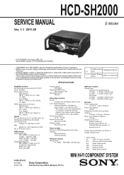
... 18 Note: IC103 (TYPE B) on the MAIN board (Suffix-12) is damaged, remove IC103 and C242 (Combination: TYPE B) and replace with single. HCD-SH2000 5-4. D1259 (DJ LED) D1280 (LED BAR2) D1290 (LED BAR1) D1251 (STANDBY LED) LED DRIVE IC1000 15 Q12 16 Q11 17 Q10 18 Q9 19 ... SG4/KS4 1 SG3/KS3 2 SG2/KS2 3 SG1/KS1 SG24/KS24 2 FL-DRIVER-CLK 1 FL-DRIVER-DATA 21 /FL-DRIVER-CS SYSTEM CONTROLLER IC100 (4/4) 10 - 33 34 - 49 REMOTE CONTROL RECEIVER IC982 MASTER DJ CONTROL S1000 ROTARY ENCODER 4 SIRCS 97 MASTER-VOL D1151 (USB B : BLUE) D1154 (USB B : RED) D1150 (USB A : BLUE) LED DRIVE...
... 18 Note: IC103 (TYPE B) on the MAIN board (Suffix-12) is damaged, remove IC103 and C242 (Combination: TYPE B) and replace with single. HCD-SH2000 5-4. D1259 (DJ LED) D1280 (LED BAR2) D1290 (LED BAR1) D1251 (STANDBY LED) LED DRIVE IC1000 15 Q12 16 Q11 17 Q10 18 Q9 19 ... SG4/KS4 1 SG3/KS3 2 SG2/KS2 3 SG1/KS1 SG24/KS24 2 FL-DRIVER-CLK 1 FL-DRIVER-DATA 21 /FL-DRIVER-CS SYSTEM CONTROLLER IC100 (4/4) 10 - 33 34 - 49 REMOTE CONTROL RECEIVER IC982 MASTER DJ CONTROL S1000 ROTARY ENCODER 4 SIRCS 97 MASTER-VOL D1151 (USB B : BLUE) D1154 (USB B : RED) D1150 (USB A : BLUE) LED DRIVE...
Service Manual
Page 44
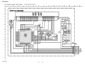
... BOARD - • See page 54 for IC Block Diagrams. 1 2 3 4 5 6 7 8 9 10 11 12 13 14 15 A B C D E F G H I J DISPLAY BOARD FL901 FLUORESCENT INDICATOR TUBE E+3.3V SIRCS IC982 REMOTE CONTROL SIGNAL RECEIVER IC982 PNA4823M03S0 VCC OUT IR GND 3.4 2.8 JL900 R900 22 C901 0.22 JL901 55 R922 0 JL902 C902 0.1 JL903 JL904 JL905 JL906 JL907 JL909 JL910... 8 JL950 7 JL948 6 JL946 5 JL944 4 JL942 3 JL940 2 JL938 1 LED_+13.5V LED_GND -VG DGND FL_DRIVER_CLK FL_DRIVER_DATA FL_DRIVER_CS +3.3V SIRCS E+3.3V K VOLUME BOARD NO1002 (Page 46) HCD-SH2000 44 44 HCD-SH2000 5-29.
... BOARD - • See page 54 for IC Block Diagrams. 1 2 3 4 5 6 7 8 9 10 11 12 13 14 15 A B C D E F G H I J DISPLAY BOARD FL901 FLUORESCENT INDICATOR TUBE E+3.3V SIRCS IC982 REMOTE CONTROL SIGNAL RECEIVER IC982 PNA4823M03S0 VCC OUT IR GND 3.4 2.8 JL900 R900 22 C901 0.22 JL901 55 R922 0 JL902 C902 0.1 JL903 JL904 JL905 JL906 JL907 JL909 JL910... 8 JL950 7 JL948 6 JL946 5 JL944 4 JL942 3 JL940 2 JL938 1 LED_+13.5V LED_GND -VG DGND FL_DRIVER_CLK FL_DRIVER_DATA FL_DRIVER_CS +3.3V SIRCS E+3.3V K VOLUME BOARD NO1002 (Page 46) HCD-SH2000 44 44 HCD-SH2000 5-29.

Service Manual
Page 61
... transfer clock signal output to "H". 13 XOUT O Main system clock output terminal (8MHz) 14 VSS - Ground terminal 15 XIN I Remote control signal input LED-DRIVER-DATA O Serial data output signal to LED Driver, R8A66166SP /LED-DRIVER-OE O Output Enable Signal to LED ...Clock Signal from MTK DMB Board 42 MTK-RESET O MTK DMB Board reset pin 43 MTK_POWER_CTRL O Power Control pin for all speaker mute control pin. HCD-SH2000 • IC Pin Function Descriptions MAIN BOARD (1/4) IC100 R5F3650KBDFA (SYSTEM CONTROL) Pin No. 1 2 3 4 5 6 7 8 9 10 11 12 Pin Name I/O Description...
... transfer clock signal output to "H". 13 XOUT O Main system clock output terminal (8MHz) 14 VSS - Ground terminal 15 XIN I Remote control signal input LED-DRIVER-DATA O Serial data output signal to LED Driver, R8A66166SP /LED-DRIVER-OE O Output Enable Signal to LED ...Clock Signal from MTK DMB Board 42 MTK-RESET O MTK DMB Board reset pin 43 MTK_POWER_CTRL O Power Control pin for all speaker mute control pin. HCD-SH2000 • IC Pin Function Descriptions MAIN BOARD (1/4) IC100 R5F3650KBDFA (SYSTEM CONTROL) Pin No. 1 2 3 4 5 6 7 8 9 10 11 12 Pin Name I/O Description...


