Operating Instructions
Page 9
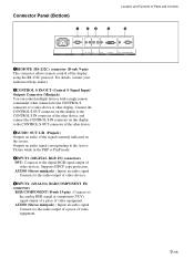
... an audio signal. Connects to the audio output of video devices. 5INPUT2 (ANALOG RGB/COMPONENT IN) connectors RGB/COMPONENT (D-sub 15-pin) : Connects to the digital RGB signal output of video equipment. For details, contact your authorized Sony dealers. 2CONTROL S IN/OUT (Control S Signal Input/ Output) Connector (Minijack).... Connects to the audio output of a piece of the display using the RS-232C protocol. Supports HDCP copy protection. Connector Panel (Bottom) 1 23 4 Location and Function of Parts and Controls 5 AC IN REMOTE IN OUT R L AUDIO CONTROL S AUDIO OUT DVI-HDCP...
... an audio signal. Connects to the audio output of video devices. 5INPUT2 (ANALOG RGB/COMPONENT IN) connectors RGB/COMPONENT (D-sub 15-pin) : Connects to the digital RGB signal output of video equipment. For details, contact your authorized Sony dealers. 2CONTROL S IN/OUT (Control S Signal Input/ Output) Connector (Minijack).... Connects to the audio output of a piece of the display using the RS-232C protocol. Supports HDCP copy protection. Connector Panel (Bottom) 1 23 4 Location and Function of Parts and Controls 5 AC IN REMOTE IN OUT R L AUDIO CONTROL S AUDIO OUT DVI-HDCP...
Operating Instructions
Page 11
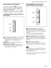
... signal to the connector, see "Pin assignment" on other optional adaptors (Not supplied), consult your Sony dealers. AUDIO VD 1RGB/COMPONENT IN (D-sub 15-pin) : Connects to an AC power or is... in the display; Optional adaptors (Not supplied) The connectors marked with 7on the connector panel are slot-in types and can be fitted with any of the optional adaptors in the standby...audio output of a piece of video equipment or a computer. Connects to the component signal input or analog RGB signal input of a piece of video equipment or a computer. 3AUDIO IN (Stereo minijack) : Inputs audio ...
... signal to the connector, see "Pin assignment" on other optional adaptors (Not supplied), consult your Sony dealers. AUDIO VD 1RGB/COMPONENT IN (D-sub 15-pin) : Connects to an AC power or is... in the display; Optional adaptors (Not supplied) The connectors marked with 7on the connector panel are slot-in types and can be fitted with any of the optional adaptors in the standby...audio output of a piece of video equipment or a computer. Connects to the component signal input or analog RGB signal input of a piece of video equipment or a computer. 3AUDIO IN (Stereo minijack) : Inputs audio ...
Operating Instructions
Page 12
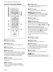
..., and User 1 to 3. 8ASPECT button Press to change the display to the standby mode. 3MUTING button Press to mute the sound. Each press toggles between RGB and COMPONENT. 7PICTURE button Selects Picture mode. Press again to restore sound. 4DISPLAY button Press to the INPUT2 connectors. Press again to hide them. Location...
..., and User 1 to 3. 8ASPECT button Press to change the display to the standby mode. 3MUTING button Press to mute the sound. Each press toggles between RGB and COMPONENT. 7PICTURE button Selects Picture mode. Press again to restore sound. 4DISPLAY button Press to the INPUT2 connectors. Press again to hide them. Location...
Operating Instructions
Page 19
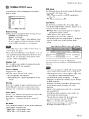
...8226; Signals of the composite synchronous signal, the image may lose the energy saving effects if you can still adjust the quality of the RGB/COMPONENT connector. However, note that you can reduce power consumption or set to "Reduce", you increase Contrast or Brightness. Notes •... There are some inputs for the synchronous mode setting, you may not be carried out for the input through the RGB connector. • With Sync On Green, if the unit is input. CUSTOM SETUP menu You can enjoy viewing pictures while reducing power...
...8226; Signals of the composite synchronous signal, the image may lose the energy saving effects if you can still adjust the quality of the RGB/COMPONENT connector. However, note that you can reduce power consumption or set to "Reduce", you increase Contrast or Brightness. Notes •... There are some inputs for the synchronous mode setting, you may not be carried out for the input through the RGB connector. • With Sync On Green, if the unit is input. CUSTOM SETUP menu You can enjoy viewing pictures while reducing power...
Operating Instructions
Page 20
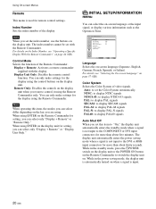
... PAL: to display PAL signals SECAM: to display SECAM signals PAL-M: to display PAL-M signals PAL-N: to display PAL-N signals PAL60: to the DVI or RGB input connectors for setting, you can select differ depending on -screen language or the input signal, or display various information such as the Operation Time...
... PAL: to display PAL signals SECAM: to display SECAM signals PAL-M: to display PAL-M signals PAL-N: to display PAL-N signals PAL60: to the DVI or RGB input connectors for setting, you can select differ depending on -screen language or the input signal, or display various information such as the Operation Time...
Operating Instructions
Page 23
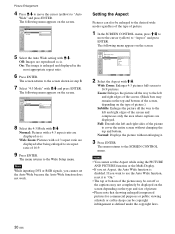
...equipment equipped with a TBC (time base corrector). Option1 S Video: Selects the signal (S video signal) input from the equipment connected to "Input2 RGB" or "Input2 Component" alternately. Option1 Video: Selects the signal (video signal) input from the equipment connected to the connectors of the option ...) input to the connectors of the menus, see "Selecting the On-screen Language" on page 37 (GB). Option1 RGB: Selects the signal (analog RGB signal) input from multiple systems, the Picture Quality setting will default to the selected input connector, the indication changes every...
...equipment equipped with a TBC (time base corrector). Option1 S Video: Selects the signal (S video signal) input from the equipment connected to "Input2 RGB" or "Input2 Component" alternately. Option1 Video: Selects the signal (video signal) input from the equipment connected to the connectors of the option ...) input to the connectors of the menus, see "Selecting the On-screen Language" on page 37 (GB). Option1 RGB: Selects the signal (analog RGB signal) input from multiple systems, the Picture Quality setting will default to the selected input connector, the indication changes every...
Operating Instructions
Page 24
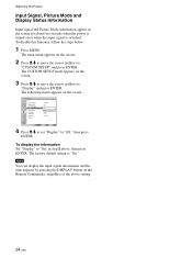
.... The following menu appears on or when the input signal is "On." CUSTOM SETUP Power Saving: Speaker Out: Closed Caption: Display: Color Matrix: HD Mode: RGB Mode: Sync Mode: Remote Standard Off Off Off OY/nPB/PR 1080i DTV H/Comp Select Set ENTER Exit MENU 4 Press M/m to set "Display" to "On...
.... The following menu appears on or when the input signal is "On." CUSTOM SETUP Power Saving: Speaker Out: Closed Caption: Display: Color Matrix: HD Mode: RGB Mode: Sync Mode: Remote Standard Off Off Off OY/nPB/PR 1080i DTV H/Comp Select Set ENTER Exit MENU 4 Press M/m to set "Display" to "On...
Operating Instructions
Page 25
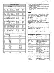
... Option 1 slot is set to composite video. Notes • When inputting an HDTV signal, input the tri-level sync signal to the 2nd pin of RGB/COMPONENT (D-sub 15 pin) on -screen display of the unit's status On-screen display 640×480 / 60 (e.g.) 480 / 60i (e.g.) NTSC (e.g.) Out ... U.S.A. The selected input signal is component video. The signal mode of the Video Electronics Standards Association. The signal mode of INPUT2 is set to analog RGB. The selected input signal is NTSC. The signal mode of Option 1 slot is set to component video. 25 (GB) The input signal is a...
... Option 1 slot is set to composite video. Notes • When inputting an HDTV signal, input the tri-level sync signal to the 2nd pin of RGB/COMPONENT (D-sub 15 pin) on -screen display of the unit's status On-screen display 640×480 / 60 (e.g.) 480 / 60i (e.g.) NTSC (e.g.) Out ... U.S.A. The selected input signal is component video. The signal mode of the Video Electronics Standards Association. The signal mode of INPUT2 is set to analog RGB. The selected input signal is NTSC. The signal mode of Option 1 slot is set to component video. 25 (GB) The input signal is a...

Operating Instructions
Page 28
.... Mid: Sets the Gamma Correct. to low. 3 Press ENTER to return to their factory presettings. Notes • You cannot adjust Chroma and Phase when an RGB signal is input. • You cannot adjust Phase when a component signal is input. • You cannot adjust Phase with M/m and press ENTER. with a PAL, PAL...
.... Mid: Sets the Gamma Correct. to low. 3 Press ENTER to return to their factory presettings. Notes • You cannot adjust Chroma and Phase when an RGB signal is input. • You cannot adjust Phase when a component signal is input. • You cannot adjust Phase with M/m and press ENTER. with a PAL, PAL...
Operating Instructions
Page 30
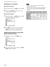
... Wide: 4:3 Mode: On NWoidrme aZloom Wide Zoom Select Set ENTER Exit MENU 8 Select the 4:3 Mode with a 4:3 aspect ratio are displayed. Note While inputting DVI or RGB signals, you set the Auto Wide because the Auto Wide function does not work. The menu returns to "On." • The top or bottom of...
... Wide: 4:3 Mode: On NWoidrme aZloom Wide Zoom Select Set ENTER Exit MENU 8 Select the 4:3 Mode with a 4:3 aspect ratio are displayed. Note While inputting DVI or RGB signals, you set the Auto Wide because the Auto Wide function does not work. The menu returns to "On." • The top or bottom of...
Operating Instructions
Page 34
Viewing two pictures at the same time Zooming in on a picture When P&P is selected 1 Select "Picture Size" with M/m and press ENTER. 2 Keep pressing
Viewing two pictures at the same time Zooming in on a picture When P&P is selected 1 Select "Picture Size" with M/m and press ENTER. 2 Keep pressing
Operating Instructions
Page 37
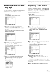
... M/m to move the cursor (yellow) to "Color Matrix" and press ENTER. CUSTOM SETUP Power Saving: Speaker Out: Closed Caption: Display: Color Matrix: HD Mode: RGB Mode: Sync Mode: Remote Standard Off Off Off Y/PB/PR 1080i DTV H/Comp Select Set ENTER Exit MENU 3 Press M/m to move the cursor (yellow) to...to return to the language of your choice and press ENTER. CUSTOM SETUP Power Saving: Speaker Out: Closed Caption: Display: Color Matrix: HD Mode: RGB Mode: Sync Mode: Remote Standard Off Off Off Y/CPB/PCR Y10/P8B0i/PR DTV H/Comp Select Set ENTER Exit MENU 4 Select the color matrix ...
... M/m to move the cursor (yellow) to "Color Matrix" and press ENTER. CUSTOM SETUP Power Saving: Speaker Out: Closed Caption: Display: Color Matrix: HD Mode: RGB Mode: Sync Mode: Remote Standard Off Off Off Y/PB/PR 1080i DTV H/Comp Select Set ENTER Exit MENU 3 Press M/m to move the cursor (yellow) to...to return to the language of your choice and press ENTER. CUSTOM SETUP Power Saving: Speaker Out: Closed Caption: Display: Color Matrix: HD Mode: RGB Mode: Sync Mode: Remote Standard Off Off Off Y/CPB/PCR Y10/P8B0i/PR DTV H/Comp Select Set ENTER Exit MENU 4 Select the color matrix ...
Operating Instructions
Page 44
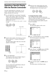
... Remote menu. The input number appears right next to the normal screen. CUSTOM SETUP Power Saving: Speaker Out: Closed Caption: Display: Color Matrix: HD Mode: RGB Mode: Sync Mode: Remote Standard Off Off Off Y/PB/PR 1080i DTV H/Comp Select Set ENTER Exit MENU 3 Select "Remote" with M /m and press ENTER. ON...
... Remote menu. The input number appears right next to the normal screen. CUSTOM SETUP Power Saving: Speaker Out: Closed Caption: Display: Color Matrix: HD Mode: RGB Mode: Sync Mode: Remote Standard Off Off Off Y/PB/PR 1080i DTV H/Comp Select Set ENTER Exit MENU 3 Select "Remote" with M /m and press ENTER. ON...
Operating Instructions
Page 45
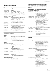
...: 700 to 140 MHz Panel system AC-type Plasma Display Panel Display resolution 1366 dots (horizontal) × 768 lines (vertical) FWD-42PV1/42PV1A: Pixel pitch 1.08 (horizontal) × 1.08 (vertical) mm (1⁄16 × 1⁄16 inches) Picture size 920 (horizontal) × 518 (vertical) mm (36 1⁄4 × 20 1⁄2 inches) Panel size 42-inch (diagonal 1056...
...: 700 to 140 MHz Panel system AC-type Plasma Display Panel Display resolution 1366 dots (horizontal) × 768 lines (vertical) FWD-42PV1/42PV1A: Pixel pitch 1.08 (horizontal) × 1.08 (vertical) mm (1⁄16 × 1⁄16 inches) Picture size 920 (horizontal) × 518 (vertical) mm (36 1⁄4 × 20 1⁄2 inches) Panel size 42-inch (diagonal 1056...
Operating Instructions
Page 46
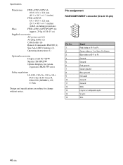
Pin assignment RGB/COMPONENT connector (D-sub 15-pin) Pin No. 1 2 3 4 5 6 7 8 9 10 11 12 13 ... Ground Ground SDA H sync or composite sync V sync SCL 46 (GB) Specifications Dimensions FWD-42PV1/42PV1A: 1033 × 631 × 121 mm (40 3⁄4 × 24 7⁄8 × 4 7⁄8 inches) FWD-42PV1P: 631 × 1033 × 121 mm (24 7⁄8 × 40 ...3⁄4 × 4 7⁄8 inches) (w/h/d, excluding projections) Mass FWD-42PV1/42PV1P/42PV1A: Approx. 29 kg (63 lb 15 oz) Supplied accessories AC power cord (1) AC plug holder (2) Cable...
Pin assignment RGB/COMPONENT connector (D-sub 15-pin) Pin No. 1 2 3 4 5 6 7 8 9 10 11 12 13 ... Ground Ground SDA H sync or composite sync V sync SCL 46 (GB) Specifications Dimensions FWD-42PV1/42PV1A: 1033 × 631 × 121 mm (40 3⁄4 × 24 7⁄8 × 4 7⁄8 inches) FWD-42PV1P: 631 × 1033 × 121 mm (24 7⁄8 × 40 ...3⁄4 × 4 7⁄8 inches) (w/h/d, excluding projections) Mass FWD-42PV1/42PV1P/42PV1A: Approx. 29 kg (63 lb 15 oz) Supplied accessories AC power cord (1) AC plug holder (2) Cable...