Operating Instructions
Page 2
...located on , the user is encouraged to try to correct the interference by one or more of Conformity Trade Name: SONY Model: FWD-42PV1/42PV1P/42PV1A Responsible Party: Sony Electronics Inc. If you carry the display unit, hold the unit itself, not the speakers. Operation is connected. ...subject to the following two conditions: (1) This device may not cause harmful interference, and (2) this equipment does cause harmful interference to Part 15 of the FCC Rules. Model No. This equipment generates, uses, and can radiate radio frequency energy and, if not installed...
...located on , the user is encouraged to try to correct the interference by one or more of Conformity Trade Name: SONY Model: FWD-42PV1/42PV1P/42PV1A Responsible Party: Sony Electronics Inc. If you carry the display unit, hold the unit itself, not the speakers. Operation is connected. ...subject to the following two conditions: (1) This device may not cause harmful interference, and (2) this equipment does cause harmful interference to Part 15 of the FCC Rules. Model No. This equipment generates, uses, and can radiate radio frequency energy and, if not installed...
Operating Instructions
Page 3
Table of Contents Precautions 5 (GB) Location and Function of Parts and Controls ....... 7 (GB) Front / Rear / Left side / Right side / Bottom .......... 7 (GB) Indicator Section 8 (GB) Control Button Section (Top 8 (GB) Connector Panel (Bottom 9 (GB) Connector Panel (Left side 10 (GB) Remote Commander RM-980 12 (GB) Caution 14 (GB) Connections 15 (GB) Connecting the Speakers...
Table of Contents Precautions 5 (GB) Location and Function of Parts and Controls ....... 7 (GB) Front / Rear / Left side / Right side / Bottom .......... 7 (GB) Indicator Section 8 (GB) Control Button Section (Top 8 (GB) Connector Panel (Bottom 9 (GB) Connector Panel (Left side 10 (GB) Remote Commander RM-980 12 (GB) Caution 14 (GB) Connections 15 (GB) Connecting the Speakers...
Operating Instructions
Page 5
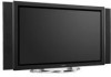
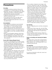
... away the carton and packing materials. When shipping the unit, repack it . On the PDP (Plasma Display Panel) • You may damage the finish of the cabinet or can generate a few dark or ...sunlight, excessive dust, mechanical vibration or shock. • When you install the unit on a part of red, blue or green remain, or dark spots appear on the carton. If light ghosting...image burn-in occurs, it will never completely disappear. • To protect the plasma display, this unit, contact your authorized Sony dealers. 5 (GB) These do not indicate malfunction. • Do not display ...
... away the carton and packing materials. When shipping the unit, repack it . On the PDP (Plasma Display Panel) • You may damage the finish of the cabinet or can generate a few dark or ...sunlight, excessive dust, mechanical vibration or shock. • When you install the unit on a part of red, blue or green remain, or dark spots appear on the carton. If light ghosting...image burn-in occurs, it will never completely disappear. • To protect the plasma display, this unit, contact your authorized Sony dealers. 5 (GB) These do not indicate malfunction. • Do not display ...
Operating Instructions
Page 7
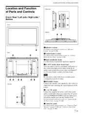
...lights up an audio/visual system (the power rating: maximum 0.5 A). Note Be sure not to connect the device of Parts and Controls Right side 4 5 SPEAKER R Bottom 67 Rear 2 45 Left side 67 7 5 1 3 57 ... 8 (GB). 2Control button section For details on the control button section, see "Connector Panel (Bottom)" on page 9 (GB) and "Connector Panel (Left side)" on page 10 (GB). 7 (GB) AC IN socket Connect the ...consuming small power to a wall outlet. For more details, consult your Sony dealer. For more details on the power cord, see "Connecting the AC Power Cord" on page 15 ...
...lights up an audio/visual system (the power rating: maximum 0.5 A). Note Be sure not to connect the device of Parts and Controls Right side 4 5 SPEAKER R Bottom 67 Rear 2 45 Left side 67 7 5 1 3 57 ... 8 (GB). 2Control button section For details on the control button section, see "Connector Panel (Bottom)" on page 9 (GB) and "Connector Panel (Left side)" on page 10 (GB). 7 (GB) AC IN socket Connect the ...consuming small power to a wall outlet. For more details, consult your Sony dealer. For more details on the power cord, see "Connecting the AC Power Cord" on page 15 ...
Operating Instructions
Page 8
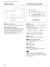
Location and Function of Parts and Controls Indicator Section Control Button Section (Top) 12 12345 6 1Remote control detector Receives the signals from the Remote Commander. 2POWER/STANDBY indicator Lights up ... installed in orange when the display enters the power saving mode while a signal is input from the INPUT or OPTION1 connector. Note To protect the panel, a certain amount of these operations before executing the next operation. 8 (GB) Press again to return to turn the unit ON/STANDBY. The signal to be...
Location and Function of Parts and Controls Indicator Section Control Button Section (Top) 12 12345 6 1Remote control detector Receives the signals from the Remote Commander. 2POWER/STANDBY indicator Lights up ... installed in orange when the display enters the power saving mode while a signal is input from the INPUT or OPTION1 connector. Note To protect the panel, a certain amount of these operations before executing the next operation. 8 (GB) Press again to return to turn the unit ON/STANDBY. The signal to be...
Operating Instructions
Page 9
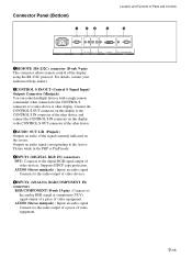
...CONTROL S IN connector on this display to the CONTROL S connector of video devices. Supports HDCP copy protection. For details, contact your authorized Sony dealers. 2CONTROL S IN/OUT (Control S Signal Input/ Output) Connector (Minijack) You can control multiple devices with a single remote commander when...RGB signal output of a video device or other device. 3AUDIO OUT L/R (Pinjack) Outputs an audio of video equipment. Connector Panel (Bottom) 1 23 4 Location and Function of Parts and Controls 5 AC IN REMOTE IN OUT R L AUDIO CONTROL S AUDIO OUT DVI-HDCP INPUT 1 AUDIO RGB/COMPONENT ...
...CONTROL S IN connector on this display to the CONTROL S connector of video devices. Supports HDCP copy protection. For details, contact your authorized Sony dealers. 2CONTROL S IN/OUT (Control S Signal Input/ Output) Connector (Minijack) You can control multiple devices with a single remote commander when...RGB signal output of a video device or other device. 3AUDIO OUT L/R (Pinjack) Outputs an audio of video equipment. Connector Panel (Bottom) 1 23 4 Location and Function of Parts and Controls 5 AC IN REMOTE IN OUT R L AUDIO CONTROL S AUDIO OUT DVI-HDCP INPUT 1 AUDIO RGB/COMPONENT ...
Operating Instructions
Page 10
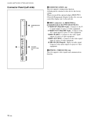
...can control the display unit via the network. 7VIDEO connectors (A BKM-FW10 is attached to the Y/C signal input of a piece of Parts and Controls Connector Panel (Left side) 6 COMMUNICATION Slot COMMUNICATION 7 8 OPTION1 (VIDEO/COM) Slot OPTION 1 (VIDEO/COM) 6COMMUNICATION slot This slot supports ... (BNC) : Connects to the audio output of a piece of video equipment. A blank panel is preinstalled only in this slot, you install the optional adaptor BKM-FW32 (Network Management Adaptor) in the FWD-42LX1/32LX1.) S VIDEO IN (Mini DIN 4-pin) : Connects to the video signal input...
...can control the display unit via the network. 7VIDEO connectors (A BKM-FW10 is attached to the Y/C signal input of a piece of Parts and Controls Connector Panel (Left side) 6 COMMUNICATION Slot COMMUNICATION 7 8 OPTION1 (VIDEO/COM) Slot OPTION 1 (VIDEO/COM) 6COMMUNICATION slot This slot supports ... (BNC) : Connects to the audio output of a piece of video equipment. A blank panel is preinstalled only in this slot, you install the optional adaptor BKM-FW32 (Network Management Adaptor) in the FWD-42LX1/32LX1.) S VIDEO IN (Mini DIN 4-pin) : Connects to the video signal input...
Operating Instructions
Page 11
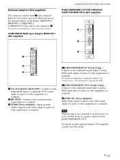
... signal. Optional adaptors (Not supplied) The connectors marked with 7on the connector panel are slot-in types and can be fitted with any of video equipment or a computer. For ...details on installation, consult your Sony dealer. 11 (GB) AUDIO VD 1RGB/COMPONENT IN (D-sub 15-pin) : Connects...of video equipment or a computer. COMPONENT/RGB Input Adaptor BKM-FW11 (Not supplied) Location and Function of Parts and Controls RGB/COMPONENT ACTIVE THROUGH ADAPTOR BKM-FW12 (Not supplied) 1 2 IN RGB/COMPONENT THROUGH OUT ...
... signal. Optional adaptors (Not supplied) The connectors marked with 7on the connector panel are slot-in types and can be fitted with any of video equipment or a computer. For ...details on installation, consult your Sony dealer. 11 (GB) AUDIO VD 1RGB/COMPONENT IN (D-sub 15-pin) : Connects...of video equipment or a computer. COMPONENT/RGB Input Adaptor BKM-FW11 (Not supplied) Location and Function of Parts and Controls RGB/COMPONENT ACTIVE THROUGH ADAPTOR BKM-FW12 (Not supplied) 1 2 IN RGB/COMPONENT THROUGH OUT ...
Operating Instructions
Page 12
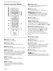
Location and Function of Parts and Controls Remote Commander RM-980 1 2 MUTING DISPLAY STBY ON 3 4 5 qf 6 qg 7 qh 8 qj 9 ENTER 123 0 456 789 qa 0 qk qs ON SET qd ql ...
Location and Function of Parts and Controls Remote Commander RM-980 1 2 MUTING DISPLAY STBY ON 3 4 5 qf 6 qg 7 qh 8 qj 9 ENTER 123 0 456 789 qa 0 qk qs ON SET qd ql ...
Operating Instructions
Page 13
qk CHROMA button Adjusts the chroma when the picture mode is set to any of "User1" to "User3." Press this button and adjust the chroma with the M/m or
qk CHROMA button Adjusts the chroma when the picture mode is set to any of "User1" to "User3." Press this button and adjust the chroma with the M/m or
Operating Instructions
Page 21
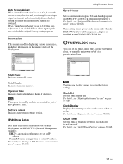
Even when input signals are not preset in memory each input signal on page 42 (GB). Serial Number Indicates the serial number. Software Version Indicates the system software version. Manual: Manual configuration to set disabled. Clock Display Displays the currently ..., or make the unit power on the menu only when the BKM-FW32 (Network Management Adaptor) is installed in standby mode is not counted as part of operation. For details, see "Setting an IP Address and communication speed" on the unit and automatically detects the last setting in the factory setting...
Even when input signals are not preset in memory each input signal on page 42 (GB). Serial Number Indicates the serial number. Software Version Indicates the system software version. Manual: Manual configuration to set disabled. Clock Display Displays the currently ..., or make the unit power on the menu only when the BKM-FW32 (Network Management Adaptor) is installed in standby mode is not counted as part of operation. For details, see "Setting an IP Address and communication speed" on the unit and automatically detects the last setting in the factory setting...


