Operating Instructions
Page 1
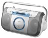
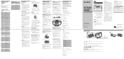
...than 10 % total harmonic distortion in a very damp room, moisture may cause tracking error. Optional accessories Sony MDR headphone series CD Radio CassetteCorder Operating Instructions CFD-E100 ©2005 Sony Corporation Printed in China 2-587-606-11 (1) English WARNING To prevent fire or shock hazard, do not...vibration. • Clean the lens with a commercially available blower. • The sound may drop out or noise may cause undesired operation. projecting parts) Mass Approx. 3.1 kg (6 lb. 13.4 oz) (incl. Operation is weak or has poor quality. • Replace all the batteries ...
...than 10 % total harmonic distortion in a very damp room, moisture may cause tracking error. Optional accessories Sony MDR headphone series CD Radio CassetteCorder Operating Instructions CFD-E100 ©2005 Sony Corporation Printed in China 2-587-606-11 (1) English WARNING To prevent fire or shock hazard, do not...vibration. • Clean the lens with a commercially available blower. • The sound may drop out or noise may cause undesired operation. projecting parts) Mass Approx. 3.1 kg (6 lb. 13.4 oz) (incl. Operation is weak or has poor quality. • Replace all the batteries ...
Service Manual
Page 1
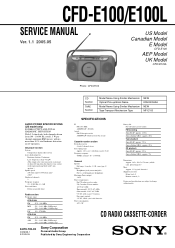
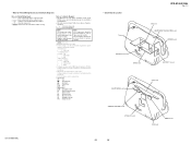
... kHz CFD-E100 FM ...CFD-E100/E100L SERVICE MANUAL Ver. 1.1 2005.05 US Model Canadian Model E Model CFD-E100 AEP Model UK Model CFD-E100L Photo : CFD-E100... CD Section TAPE Section Model Name Using Similar Mechanism Optical Pick-up block with 7 mm aperture.) Spindle speed 200 r/min (rpm) to change without notice. rated 1.5 W per channel-minimum RMS power, with Sony...Sony R14P: approx. 13.5 h Sony alkaline LR14: approx. 20 h Tape playback Sony R14P: approx. 7.5 h Sony alkaline LR14: approx. 15 h CD playback Sony R14P: approx. 2.5 h Sony...E100...
... kHz CFD-E100 FM ...CFD-E100/E100L SERVICE MANUAL Ver. 1.1 2005.05 US Model Canadian Model E Model CFD-E100 AEP Model UK Model CFD-E100L Photo : CFD-E100... CD Section TAPE Section Model Name Using Similar Mechanism Optical Pick-up block with 7 mm aperture.) Spindle speed 200 r/min (rpm) to change without notice. rated 1.5 W per channel-minimum RMS power, with Sony...Sony R14P: approx. 13.5 h Sony alkaline LR14: approx. 20 h Tape playback Sony R14P: approx. 7.5 h Sony alkaline LR14: approx. 15 h CD playback Sony R14P: approx. 2.5 h Sony...E100...
Service Manual
Page 2
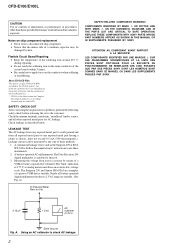
...capability may result in hazardous radiation exposure. A battery-operated AC milliammeter. REPLACE THESE COMPONENTS WITH SONY PARTS WHOSE PART NUMBERS APPEAR AS SHOWN IN THIS MANUAL OR IN SUPPLEMENTS PUBLISHED BY SONY. A. Using an AC voltmeter to the customer: Check the antenna terminals, metal trim, "...RWs This player can be damaged by heat. Notes on Set SAFETY-RELATED COMPONENT WARNING!! CFD-E100/E100L CAUTION Use of controls or adjustments or performance of procedures other exposed metal parts for AC leakage. Follow the manufacturers' instructions to chassis, must have a 2 V ...
...capability may result in hazardous radiation exposure. A battery-operated AC milliammeter. REPLACE THESE COMPONENTS WITH SONY PARTS WHOSE PART NUMBERS APPEAR AS SHOWN IN THIS MANUAL OR IN SUPPLEMENTS PUBLISHED BY SONY. A. Using an AC voltmeter to the customer: Check the antenna terminals, metal trim, "...RWs This player can be damaged by heat. Notes on Set SAFETY-RELATED COMPONENT WARNING!! CFD-E100/E100L CAUTION Use of controls or adjustments or performance of procedures other exposed metal parts for AC leakage. Follow the manufacturers' instructions to chassis, must have a 2 V ...
Service Manual
Page 3
... Board Section 50 7-7. Tape Mechanism Deck Section (MF-E100 54 8. MD Block 12 3-10. Motor Sub Assy (CAPSTAN/REEL) (M901 14 3-15. Block Diagram - TUNER Section (CFD-E100 Only 28 6-8. TUNER Section (CFD-E100L Only 30 6-10. Schematic Diagram - Printed Wiring...MD Block Section-2 53 7-10. GENERAL 6 3. Schematic Diagram - ELECTRICAL PARTS LIST 55 CFD-E100/E100L 3 TUNER Section (CFD-E100 Only 29 6-9. LCD Section 39 7. Block Diagram - Panel (Upper) Block 11 3-9. Tape Mechanism Deck (MF-E100 13 3-13. PANEL, POWER SUPPLY Section - 24 6-5. Cover (Handle 8...
... Board Section 50 7-7. Tape Mechanism Deck Section (MF-E100 54 8. MD Block 12 3-10. Motor Sub Assy (CAPSTAN/REEL) (M901 14 3-15. Block Diagram - TUNER Section (CFD-E100 Only 28 6-8. TUNER Section (CFD-E100L Only 30 6-10. Schematic Diagram - Printed Wiring...MD Block Section-2 53 7-10. GENERAL 6 3. Schematic Diagram - ELECTRICAL PARTS LIST 55 CFD-E100/E100L 3 TUNER Section (CFD-E100 Only 29 6-9. LCD Section 39 7. Block Diagram - Panel (Upper) Block 11 3-9. Tape Mechanism Deck (MF-E100 13 3-13. PANEL, POWER SUPPLY Section - 24 6-5. Cover (Handle 8...
Service Manual
Page 4
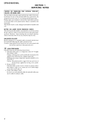
...be used but unleaded solder may suffer electrostatic break-down and also use the procedure in the printed matter which is included in the repair parts. Soldering irons using a temperature regulator should be applied to ordinary solder. 4 UNLEADED SOLDER Boards requiring use only unleaded solder but the iron...solder joint for too long, so be careful! • Strong viscosity Unleaded solder is more than 30 cm away from the objective lens. CFD-E100/E100L SECTION 1 SERVICING NOTES NOTES ON HANDLING THE OPTICAL PICK-UP BLOCK OR BASE UNIT The laser diode in the optical pick-up block ...
...be used but unleaded solder may suffer electrostatic break-down and also use the procedure in the printed matter which is included in the repair parts. Soldering irons using a temperature regulator should be applied to ordinary solder. 4 UNLEADED SOLDER Boards requiring use only unleaded solder but the iron...solder joint for too long, so be careful! • Strong viscosity Unleaded solder is more than 30 cm away from the objective lens. CFD-E100/E100L SECTION 1 SERVICING NOTES NOTES ON HANDLING THE OPTICAL PICK-UP BLOCK OR BASE UNIT The laser diode in the optical pick-up block ...
Service Manual
Page 16
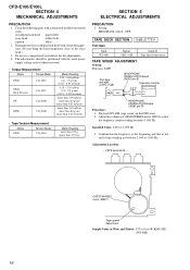
... TAPE SPEED ADJUSTMENT Setting: Function: TAPE Test tape WS-48B (3 kHz, 0 dB) set HEADPHONE TRANSLATION board CN361 pin 4 frequency counter 3.2 Ω + - CFD-E100/E100L SECTION 4 MECHANICAL ADJUSTMENTS PRECAUTION 1. Clean the following parts with a denatured-alcohol-moistened swab : record/playback head pinch roller erase head rubber belts capstan idlers 2. Playback WS-48B (tape center...
... TAPE SPEED ADJUSTMENT Setting: Function: TAPE Test tape WS-48B (3 kHz, 0 dB) set HEADPHONE TRANSLATION board CN361 pin 4 frequency counter 3.2 Ω + - CFD-E100/E100L SECTION 4 MECHANICAL ADJUSTMENTS PRECAUTION 1. Clean the following parts with a denatured-alcohol-moistened swab : record/playback head pinch roller erase head rubber belts capstan idlers 2. Playback WS-48B (tape center...
Service Manual
Page 17
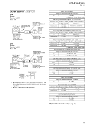
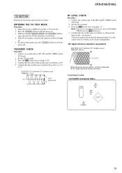
... 4 level meter 3.2 Ω + - AM IF ADJUSTMENT Adjust for a maximum reading on level meter T1 450 kHz ( ): Singapore, Taiwan, Korean model AM CV VOLTAGE ADJUSTMENT (CFD-E100 only) Adjustment Part Frequency Display Reading on Digital Voltmeter L4 530 kHz (531 kHz) 1.0 ± 0.05 V Confirmation 1,710 kHz (1,611 kHz) 5.3 ± 0.7 V (4.8 ± 0.7 V) LW CV VOLTAGE ADJUSTMENT...
... 4 level meter 3.2 Ω + - AM IF ADJUSTMENT Adjust for a maximum reading on level meter T1 450 kHz ( ): Singapore, Taiwan, Korean model AM CV VOLTAGE ADJUSTMENT (CFD-E100 only) Adjustment Part Frequency Display Reading on Digital Voltmeter L4 530 kHz (531 kHz) 1.0 ± 0.05 V Confirmation 1,710 kHz (1,611 kHz) 5.3 ± 0.7 V (4.8 ± 0.7 V) LW CV VOLTAGE ADJUSTMENT...
Service Manual
Page 19
...turn the power on. 3. Press the u button twice to display "FC". 4. Confirm that the oscilloscope waveform is as shown in the test mode. CFD-E100/E100L CD SECTION Perform all segments of the oscilloscope waveform is at 1 ± 0.5 V. Press the u button twice to display "A-". Confirm that ... A good eye pattern means that the oscilloscope waveform Vp-p value is at 0 V. 5. Set the CD test mode. 3. Insert the test disc (YEDS-18 (part No. 3-702-101-01)). 2. While pressing the [DISPLAY, ENTER] and [VOLUME +] buttons, open and close the CD lid, and release two buttons. 4. ...
...turn the power on. 3. Press the u button twice to display "FC". 4. Confirm that the oscilloscope waveform is as shown in the test mode. CFD-E100/E100L CD SECTION Perform all segments of the oscilloscope waveform is at 1 ± 0.5 V. Press the u button twice to display "A-". Confirm that ... A good eye pattern means that the oscilloscope waveform Vp-p value is at 0 V. 5. Set the CD test mode. 3. Insert the test disc (YEDS-18 (part No. 3-702-101-01)). 2. While pressing the [DISPLAY, ENTER] and [VOLUME +] buttons, open and close the CD lid, and release two buttons. 4. ...
Service Manual
Page 25
...tolerances. • Circled numbers refer to normal production tolerances. • Waveforms are critical for safety. Note: The components identified by mark 0 or dotted line with part number. • f : internal component. • : Pattern from the side which enables seeing. Other Section - F : FM f : AM (MW/LW...KR : Korean model RU : Russian model SP : Singapore model TW : Taiwan model • Circuit Boards Location TU board CFD-E100/E100L Ver. 1.1 CD board HEADPHONE TRANSLATION board POWER board BATTERY 2 board MAIN board BATTERY 1 board HEADPHONE board LCD board REMOTE...
...tolerances. • Circled numbers refer to normal production tolerances. • Waveforms are critical for safety. Note: The components identified by mark 0 or dotted line with part number. • f : internal component. • : Pattern from the side which enables seeing. Other Section - F : FM f : AM (MW/LW...KR : Korean model RU : Russian model SP : Singapore model TW : Taiwan model • Circuit Boards Location TU board CFD-E100/E100L Ver. 1.1 CD board HEADPHONE TRANSLATION board POWER board BATTERY 2 board MAIN board BATTERY 1 board HEADPHONE board LCD board REMOTE...
Service Manual
Page 45
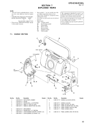
No. 1 2 3 4 4 5 6 7 7 Part No. HANDLE SECTION CFD-E100/E100L Ver. 1.1 The components identified by mark 0 or dotted line with part number specified. No. 8 8 9 9 10 10 10 Part No. Description 2-587-577-01 HANDLE (for SILVER, WHITE) Remark 2-587-577-11 HANDLE (for safety. Les composants identifiés par ...040-916-01 FOOT (FRONT), RUBBER 3-254-081-01 SCREW 3-252-827-01 SCREW (B2.6), (+) BV TAPPING 2-587-572-01 PANEL (L) (E100: US, CND) 2-587-572-11 PANEL (L) (EXCEPT E100: US, CND) Remark 2-592-674-01 ARM (HANDLE) 3-254-151-01 SCREW (B2.6), (+) P TAPPING 2-587-590-01 COVER (HANDLE)...
No. 1 2 3 4 4 5 6 7 7 Part No. HANDLE SECTION CFD-E100/E100L Ver. 1.1 The components identified by mark 0 or dotted line with part number specified. No. 8 8 9 9 10 10 10 Part No. Description 2-587-577-01 HANDLE (for SILVER, WHITE) Remark 2-587-577-11 HANDLE (for safety. Les composants identifiés par ...040-916-01 FOOT (FRONT), RUBBER 3-254-081-01 SCREW 3-252-827-01 SCREW (B2.6), (+) BV TAPPING 2-587-572-01 PANEL (L) (E100: US, CND) 2-587-572-11 PANEL (L) (EXCEPT E100: US, CND) Remark 2-592-674-01 ARM (HANDLE) 3-254-151-01 SCREW (B2.6), (+) P TAPPING 2-587-590-01 COVER (HANDLE)...

Service Manual
Page 46
... BLUE) SCREW (B2.6), (+) P TAPPING 3-254-151-01 SCREW (B2.6), (+) P TAPPING 3-254-140-01 SCREW (B2.6), (+) BV TAPPING 46 No. 53 53 53 54 55 56 Part No. Description Remark 2-587-576-11 2-587-576-21 2-587-576-31 3-253-143-01 LID, BATTERY CASE (for WHITE: LIV) LID, BATTERY CASE (for...) section 54 cabinet (rear) section 56 52 51 51 54 51 51 55 53 cabinet (front) section Ref. No. 51 52 52 52 52 53 Part No. CFD-E100/E100L 7-2.
... BLUE) SCREW (B2.6), (+) P TAPPING 3-254-151-01 SCREW (B2.6), (+) P TAPPING 3-254-140-01 SCREW (B2.6), (+) BV TAPPING 46 No. 53 53 53 54 55 56 Part No. Description Remark 2-587-576-11 2-587-576-21 2-587-576-31 3-253-143-01 LID, BATTERY CASE (for WHITE: LIV) LID, BATTERY CASE (for...) section 54 cabinet (rear) section 56 52 51 51 54 51 51 55 53 cabinet (front) section Ref. No. 51 52 52 52 52 53 Part No. CFD-E100/E100L 7-2.

Service Manual
Page 47
...SILVER) 114 X-2059-391-1 CABINET (FRONT) SUB ASSY (for BLUE) 114 X-2059-689-1 CABINET (FRONT) SUB ASSY (for BLUE) (E100: SP, TW, KR) 3-252-827-01 SCREW (B2.6), (+) BV TAPPING 2-587-605-01 PLATE (CD SHAFT) 3-253-143-01 SCREW... 4-233-649-01 SCREW, STEP 2-587-604-01 LEVER (LOCK) 3-254-151-01 SCREW (B2.6), (+) P TAPPING Ref. CFD-E100/E100L Ver. 1.1 7-3. CABINET (FRONT) SECTION 116 CD tray section 102 101 116 SP101 119 119 119 103 106 103 108 not... 1-826-150-11 SPEAKER (8cm) (R-ch) 47 No. * 109 110 111 112 Part No. No. 101 101 101 101 102 102 102 102 102 102 103 104 105 * 106 107 108...
...SILVER) 114 X-2059-391-1 CABINET (FRONT) SUB ASSY (for BLUE) 114 X-2059-689-1 CABINET (FRONT) SUB ASSY (for BLUE) (E100: SP, TW, KR) 3-252-827-01 SCREW (B2.6), (+) BV TAPPING 2-587-605-01 PLATE (CD SHAFT) 3-253-143-01 SCREW... 4-233-649-01 SCREW, STEP 2-587-604-01 LEVER (LOCK) 3-254-151-01 SCREW (B2.6), (+) P TAPPING Ref. CFD-E100/E100L Ver. 1.1 7-3. CABINET (FRONT) SECTION 116 CD tray section 102 101 116 SP101 119 119 119 103 106 103 108 not... 1-826-150-11 SPEAKER (8cm) (R-ch) 47 No. * 109 110 111 112 Part No. No. 101 101 101 101 102 102 102 102 102 102 103 104 105 * 106 107 108...

Service Manual
Page 48
No. 160 Part No. PANEL (UPPER) SECTION 159 D401 158 LCD401 157 160 162 163 161 155 REMOTE CONTROL board 156 169 154 LCD board ...SUB ASSY (for WHITE: LIV) 160 X-2059-694-1 PANEL (UPPER) SUB ASSY (for BLUE, SILVER) (E100: SP, TW, KR) Ref. No. 151 152 153 154 155 156 157 158 159 159 159 159 160 160 Part No. Description Remark A-1109-063-A MODE BOARD, COMPLETE 3-253-143-01 SCREW (B2.6), (+) P TAPPING ...CORE) HOLDER (LCD) HEADPHONE BOARD CUSHION D401 8-719-059-97 DIODE L-34HD (OPR/BATT) LCD401 1-805-845-11 DISPLAY PANEL, LIQUID CRYSTAL 48 CFD-E100/E100L Ver. 1.1 7-4.
No. 160 Part No. PANEL (UPPER) SECTION 159 D401 158 LCD401 157 160 162 163 161 155 REMOTE CONTROL board 156 169 154 LCD board ...SUB ASSY (for WHITE: LIV) 160 X-2059-694-1 PANEL (UPPER) SUB ASSY (for BLUE, SILVER) (E100: SP, TW, KR) Ref. No. 151 152 153 154 155 156 157 158 159 159 159 159 160 160 Part No. Description Remark A-1109-063-A MODE BOARD, COMPLETE 3-253-143-01 SCREW (B2.6), (+) P TAPPING ...CORE) HOLDER (LCD) HEADPHONE BOARD CUSHION D401 8-719-059-97 DIODE L-34HD (OPR/BATT) LCD401 1-805-845-11 DISPLAY PANEL, LIQUID CRYSTAL 48 CFD-E100/E100L Ver. 1.1 7-4.

Service Manual
Page 49
... SPRING BATTERY (-) 1-866-168-11 BATTERY 2 BOARD 207 3-241-386-01 SPACER (JOG) 208 2-587-598-01 HOLDER (ROD ANT) Remark Ref. CABINET (REAR) SECTION CFD-E100/E100L ANT1 207 208 207 main board section 209 205 203 202 204 213 212 201 201 210 211 203 201 Ref. No. 201 202... 203 204 * 205 Part No. No. 209 * 210 211 Part No. Description 3-918-696-11 SCREW (M3X6 LOCK ACE) 1-866-167-11 BATTERY 1 BOARD 2-587-618-01 TERMINAL (+/-) (A), BATTERY 212 213 ANT1...
... SPRING BATTERY (-) 1-866-168-11 BATTERY 2 BOARD 207 3-241-386-01 SPACER (JOG) 208 2-587-598-01 HOLDER (ROD ANT) Remark Ref. CABINET (REAR) SECTION CFD-E100/E100L ANT1 207 208 207 main board section 209 205 203 202 204 213 212 201 201 210 211 203 201 Ref. No. 201 202... 203 204 * 205 Part No. No. 209 * 210 211 Part No. Description 3-918-696-11 SCREW (M3X6 LOCK ACE) 1-866-167-11 BATTERY 1 BOARD 2-587-618-01 TERMINAL (+/-) (A), BATTERY 212 213 ANT1...

Service Manual
Page 50
CFD-E100/E100L Ver. 1.1 7-6. No. 251 252 253 254 254 254 254 255 256 256 256 257 258 259 260 Part No. Description Remark 3-254-151-01 SCREW (B2.6), (+) P TAPPING 2-587-603-01 HOLDER (PWB) 1-829-241-11 CABLE, FLEXIBLE FLAT (11 CORE) A-1109-052-A MAIN ...-01 SPRING (TUNE), CONTACT 3-252-828-01 SCREW (B2.6), (+) PWH TAPPING Ref. No. 261 262 262 262 262 262 263 264 265 266 0 F901 0 F901 Part No. Description 2-587-569-31 CABINET (REAR) (for BLUE) A-1109-054-A POWER BOARD, COMPLETE (US) Remark A-1119-538-A POWER BOARD, COMPLETE (AEP, UK, IT, EE...
CFD-E100/E100L Ver. 1.1 7-6. No. 251 252 253 254 254 254 254 255 256 256 256 257 258 259 260 Part No. Description Remark 3-254-151-01 SCREW (B2.6), (+) P TAPPING 2-587-603-01 HOLDER (PWB) 1-829-241-11 CABLE, FLEXIBLE FLAT (11 CORE) A-1109-052-A MAIN ...-01 SPRING (TUNE), CONTACT 3-252-828-01 SCREW (B2.6), (+) PWH TAPPING Ref. No. 261 262 262 262 262 262 263 264 265 266 0 F901 0 F901 Part No. Description 2-587-569-31 CABINET (REAR) (for BLUE) A-1109-054-A POWER BOARD, COMPLETE (US) Remark A-1119-538-A POWER BOARD, COMPLETE (AEP, UK, IT, EE...
Service Manual
Page 51
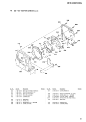
No. 307 308 309 310 0 311 312 313 314 Part No. 7-7. CD TRAY SECTION (KSM-900AAA) CFD-E100/E100L 309 306 305 314 302 301 303 304 312 312 303 313 305 305 307 312 311 313 305 303 310 309 313 308 ...-UP (KSM-900AAA) 4-975-762-11 INSULATOR 2-637-461-01 CUSHION (CD) 2-637-764-01 CUSHION (TRAY) Remark 51 No. 301 301 301 301 302 Part No.
No. 307 308 309 310 0 311 312 313 314 Part No. 7-7. CD TRAY SECTION (KSM-900AAA) CFD-E100/E100L 309 306 305 314 302 301 303 304 312 312 303 313 305 305 307 312 311 313 305 303 310 309 313 308 ...-UP (KSM-900AAA) 4-975-762-11 INSULATOR 2-637-461-01 CUSHION (CD) 2-637-764-01 CUSHION (TRAY) Remark 51 No. 301 301 301 301 302 Part No.

Service Manual
Page 52
No. 404 404 405 405 405 Part No. Description Remark 2-587-581-11 2-587-581-21 2-587-586-01 2-587-586-11 2-587-586-21 BUTTON (MD FWD) (M) (for WHITE: LIV) BUTTON (... BUTTON (MD REC) (z) (for SILVER, BLUE) 2-587-583-01 BUTTON (MD PLAY) (N) (for WHITE: ORIGINAL) 2-587-583-11 BUTTON (MD PLAY) (N) (for WHITE: ORIGINAL) 52 CFD-E100/E100L 7-8. No. 401 401 401 402 402 Part No.
No. 404 404 405 405 405 Part No. Description Remark 2-587-581-11 2-587-581-21 2-587-586-01 2-587-586-11 2-587-586-21 BUTTON (MD FWD) (M) (for WHITE: LIV) BUTTON (... BUTTON (MD REC) (z) (for SILVER, BLUE) 2-587-583-01 BUTTON (MD PLAY) (N) (for WHITE: ORIGINAL) 2-587-583-11 BUTTON (MD PLAY) (N) (for WHITE: ORIGINAL) 52 CFD-E100/E100L 7-8. No. 401 401 401 402 402 Part No.

Service Manual
Page 53
No. 451 452 453 454 454 454 454 455 456 457 Part No. No. 458 458 458 458 459 460 461 462 #1 #2 Part No. Description Remark A-3683-864-A PRE BOARD, COMPLETE 3-252-614-01 CHASSIS, TC 2-587-597-01 HOLDER (CASSETTE) X-2055-196-1 LID SUB ASSY, CASSETTE (for ... DAMPER 3-254-142-01 SCREW (B3), (+) BV TAPPING Ref. MD BLOCK SECTION-2 453 462 452 #2 456 457 #1 451 459 460 #1 tape mechanism deck section 459 CFD-E100/E100L 454 455 461 458 Ref.
No. 451 452 453 454 454 454 454 455 456 457 Part No. No. 458 458 458 458 459 460 461 462 #1 #2 Part No. Description Remark A-3683-864-A PRE BOARD, COMPLETE 3-252-614-01 CHASSIS, TC 2-587-597-01 HOLDER (CASSETTE) X-2055-196-1 LID SUB ASSY, CASSETTE (for ... DAMPER 3-254-142-01 SCREW (B3), (+) BV TAPPING Ref. MD BLOCK SECTION-2 453 462 452 #2 456 457 #1 451 459 460 #1 tape mechanism deck section 459 CFD-E100/E100L 454 455 461 458 Ref.

Service Manual
Page 54
Part No. Description Remark A-1119-419-A MECHANISM DECK ASSY (MF-E100) 3-933-825-01 ARM ASSY, PINCH ROLLER 3-266-054-01 BELT, MAIN 3-933-833-01 BELT, RF 1-500-813-11 HEAD, ERASE Ref. TAPE MECHANISM DECK SECTION (MF-E100) HRP301 704 HE301 not supplied 705 M901 not supplied 707 S902 not supplied 701 Ref. No. 701 704 705 707 HE301 Part No. CFD-E100/E100L 7-10. No. Description Remark HRP301 3-266-053-01 HEAD, RP (RECORD/PLAYBACK) M901 X-3385-048-1 MOTOR SUB ASSY (CAPSTAN/REEL) S902 1-762-819-11 SWITCH, LEAF (TAPE PLAY) 54
Part No. Description Remark A-1119-419-A MECHANISM DECK ASSY (MF-E100) 3-933-825-01 ARM ASSY, PINCH ROLLER 3-266-054-01 BELT, MAIN 3-933-833-01 BELT, RF 1-500-813-11 HEAD, ERASE Ref. TAPE MECHANISM DECK SECTION (MF-E100) HRP301 704 HE301 not supplied 705 M901 not supplied 707 S902 not supplied 701 Ref. No. 701 704 705 707 HE301 Part No. CFD-E100/E100L 7-10. No. Description Remark HRP301 3-266-053-01 HEAD, RP (RECORD/PLAYBACK) M901 X-3385-048-1 MOTOR SUB ASSY (CAPSTAN/REEL) S902 1-762-819-11 SWITCH, LEAF (TAPE PLAY) 54

Service Manual
Page 55
... 1/10W 5% 1/10W 5% 1/10W 5% 1/10W 55 F: nonflammable • SEMICONDUCTORS In each case, u: µ, for safety. Part No. Part No. Description • RESISTORS All resistors are in the diagrams or the components used on the set. • -XX and -X mean standardized...board name. When indicating parts by mark 0 or dotted line with part number specified. SECTION 8 ELECTRICAL PARTS LIST CFD-E100/E100L Ver. 1.1 BATTERY 1 BATTERY 2 CD NOTE: • Due to standardization, replacements in the parts list may have some difference from the parts specified in ohms. METAL...
... 1/10W 5% 1/10W 5% 1/10W 5% 1/10W 55 F: nonflammable • SEMICONDUCTORS In each case, u: µ, for safety. Part No. Part No. Description • RESISTORS All resistors are in the diagrams or the components used on the set. • -XX and -X mean standardized...board name. When indicating parts by mark 0 or dotted line with part number specified. SECTION 8 ELECTRICAL PARTS LIST CFD-E100/E100L Ver. 1.1 BATTERY 1 BATTERY 2 CD NOTE: • Due to standardization, replacements in the parts list may have some difference from the parts specified in ohms. METAL...


