Operating Instructions
Page 1
... the player using the remote. • Check that the product needs adjustment or modification. After trying the above remedies, if you press an operation button. • Close the cassette compartment securely. rated 1.5 W per channel-minimum RMS power, with adhesive tape. Other specifications CD player section System Compact disc digital audio system Laser diode properties Emission duration: Continuous Laser output: Less than 3 minutes to the wall outlet securely. • Make sure the batteries are...
... the player using the remote. • Check that the product needs adjustment or modification. After trying the above remedies, if you press an operation button. • Close the cassette compartment securely. rated 1.5 W per channel-minimum RMS power, with adhesive tape. Other specifications CD player section System Compact disc digital audio system Laser diode properties Emission duration: Continuous Laser output: Less than 3 minutes to the wall outlet securely. • Make sure the batteries are...
Operating Instructions
Page 2
... "Playing a CD"). Set the TV•CD/RADIO switch as follows: To repeat a single track repeat all the tracks once. Playing a CD 1 Press Z OPEN to open the tape compartment and insert a recorded tape. Using the display To check the total track number and playing time Press DISPLAY•ENTER/MEMORY in the display. Note When using the other (non-Sony) manufacturers' components, or to use the code number 011. Use TYPE I (normal) tape only. 2 Press N. Insert a tape or disc if necessary. 2 While pressing SET, press POWER. 3 Press the button...
... "Playing a CD"). Set the TV•CD/RADIO switch as follows: To repeat a single track repeat all the tracks once. Playing a CD 1 Press Z OPEN to open the tape compartment and insert a recorded tape. Using the display To check the total track number and playing time Press DISPLAY•ENTER/MEMORY in the display. Note When using the other (non-Sony) manufacturers' components, or to use the code number 011. Use TYPE I (normal) tape only. 2 Press N. Insert a tape or disc if necessary. 2 While pressing SET, press POWER. 3 Press the button...
Service Manual
Page 1
... Speaker Full range: 8 cm dia., 3.2 Ω, cone type (2) Outputs Headphones jack (stereo minijack) For 16 - 68 Ω impedance headphones Maximum Power output 3.6 W Power requirements For CD radio cassette-corder: US, Canadian, Taiwan models: 120 V AC, 60Hz Korean model: 220 V AC, 60Hz Other models: 230 V AC, 50Hz 9 V DC, 6 R14 (size C) batteries For remote control: 3 V DC, 2 R03 (size AAA) batteries Power consumption AC 14 W Battery life For CD radio cassette-corder: FM recording Sony R14P: approx. 13.5 h Sony alkaline LR14: approx. 20 h Tape playback Sony...
... Speaker Full range: 8 cm dia., 3.2 Ω, cone type (2) Outputs Headphones jack (stereo minijack) For 16 - 68 Ω impedance headphones Maximum Power output 3.6 W Power requirements For CD radio cassette-corder: US, Canadian, Taiwan models: 120 V AC, 60Hz Korean model: 220 V AC, 60Hz Other models: 230 V AC, 50Hz 9 V DC, 6 R14 (size C) batteries For remote control: 3 V DC, 2 R03 (size AAA) batteries Power consumption AC 14 W Battery life For CD radio cassette-corder: FM recording Sony R14P: approx. 13.5 h Sony alkaline LR14: approx. 20 h Tape playback Sony...
Service Manual
Page 2
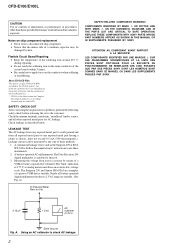
... DOTTED LINE WITH MARK 0 ON THE SCHEMATIC DIAGRAMS AND IN THE PARTS LIST ARE CRITICAL TO SAFE OPERATION. Flexible Circuit Board Repairing • Keep the temperature of the soldering iron around 270 ˚C during repairing. • Do not touch the soldering iron on Set SAFETY-RELATED COMPONENT WARNING!! Leakage current can play CD-Rs/CD-RWs recorded in hazardous radiation exposure. About CD-Rs/CD...
... DOTTED LINE WITH MARK 0 ON THE SCHEMATIC DIAGRAMS AND IN THE PARTS LIST ARE CRITICAL TO SAFE OPERATION. Flexible Circuit Board Repairing • Keep the temperature of the soldering iron around 270 ˚C during repairing. • Do not touch the soldering iron on Set SAFETY-RELATED COMPONENT WARNING!! Leakage current can play CD-Rs/CD-RWs recorded in hazardous radiation exposure. About CD-Rs/CD...
Service Manual
Page 3
... Section 35 6-15. POWER Section 37 6-17. Schematic Diagram - Tape Mechanism Deck Section (MF-E100 54 8. PANEL, POWER SUPPLY Section - 24 6-5. Printed Wiring Board - Panel (Upper) Block 11 3-9. Block Diagram - Block Diagram - Schematic Diagram - LCD Section 38 6-18. Disassembly Flow 7 3-2. Schematic Diagram - EXPLODED VIEWS 7-1. MECHANICAL ADJUSTMENTS 16 5. Block Diagram - Printed Wiring Board - SERVICING NOTES 4 2. Handle Section 45 7-2. GENERAL 6 3. ELECTRICAL ADJUSTMENTS 16 6. MAIN Board 12 3-11. CD Section 26 6-6.
... Section 35 6-15. POWER Section 37 6-17. Schematic Diagram - Tape Mechanism Deck Section (MF-E100 54 8. PANEL, POWER SUPPLY Section - 24 6-5. Printed Wiring Board - Panel (Upper) Block 11 3-9. Block Diagram - Block Diagram - Schematic Diagram - LCD Section 38 6-18. Disassembly Flow 7 3-2. Schematic Diagram - EXPLODED VIEWS 7-1. MECHANICAL ADJUSTMENTS 16 5. Block Diagram - Printed Wiring Board - SERVICING NOTES 4 2. Handle Section 45 7-2. GENERAL 6 3. ELECTRICAL ADJUSTMENTS 16 6. MAIN Board 12 3-11. CD Section 26 6-6.
Service Manual
Page 4
... on the disc reflective surface by the charged electrostatic load, etc. Therefore, when checking the laser diode emission, observe from the objective lens. During repair, pay attention to electrostatic break-down because of unleaded solder are printed with ordinary solder It is concentrated so as to be focused on this model is best to use only unleaded...
... on the disc reflective surface by the charged electrostatic load, etc. Therefore, when checking the laser diode emission, observe from the objective lens. During repair, pay attention to electrostatic break-down because of unleaded solder are printed with ordinary solder It is concentrated so as to be focused on this model is best to use only unleaded...
Service Manual
Page 6
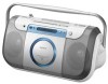
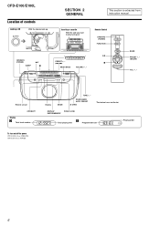
...up OPERATE (POWER) SLEEP u* x SECTION 2 GENERAL Inserting a cassette With the side you want to play facing out * PRESET +, - .,> MEGA BASS VOLUME +*, - CFD-E100: Press POWER. This section is extracted from instruction manual. Remote Control OPERATE (POWER) FUNCTION u x BAND PRESET +, - .,> VOL +*, - Display MODE TUNE +, - DISPLAY PUSH CLOSE ENTER/MEMORY Total playing time E Programmed track Playing order 6 i Remote sensor OPR/BATT Display D Total track number To turn on/off the power CFD-E100L: Press OPERATE. RADIO•BAND AUTO PRESET Z OPEN *The button has...
...up OPERATE (POWER) SLEEP u* x SECTION 2 GENERAL Inserting a cassette With the side you want to play facing out * PRESET +, - .,> MEGA BASS VOLUME +*, - CFD-E100: Press POWER. This section is extracted from instruction manual. Remote Control OPERATE (POWER) FUNCTION u x BAND PRESET +, - .,> VOL +*, - Display MODE TUNE +, - DISPLAY PUSH CLOSE ENTER/MEMORY Total playing time E Programmed track Playing order 6 i Remote sensor OPR/BATT Display D Total track number To turn on/off the power CFD-E100L: Press OPERATE. RADIO•BAND AUTO PRESET Z OPEN *The button has...
Service Manual
Page 16
... the record/playback head with the rated power supply voltage unless otherwise noted. • Torque Measurement Mode Torque Meter...Tape speed Adjustment Sample Value of tape winding are between 2,940 to 3,060 Hz. Do not use a magnetized screwdriver for Tape Speed Adjustment TAPE SPEED ADJUSTMENT Setting: Function: TAPE Test tape WS-48B (3 kHz, 0 dB) set HEADPHONE TRANSLATION board CN361 pin 4 frequency counter 3.2 Ω + - CFD-E100/E100L SECTION 4 MECHANICAL ADJUSTMENTS PRECAUTION 1. Clean the following parts with a denatured-alcohol-moistened swab : record/playback...
... the record/playback head with the rated power supply voltage unless otherwise noted. • Torque Measurement Mode Torque Meter...Tape speed Adjustment Sample Value of tape winding are between 2,940 to 3,060 Hz. Do not use a magnetized screwdriver for Tape Speed Adjustment TAPE SPEED ADJUSTMENT Setting: Function: TAPE Test tape WS-48B (3 kHz, 0 dB) set HEADPHONE TRANSLATION board CN361 pin 4 frequency counter 3.2 Ω + - CFD-E100/E100L SECTION 4 MECHANICAL ADJUSTMENTS PRECAUTION 1. Clean the following parts with a denatured-alcohol-moistened swab : record/playback...
Service Manual
Page 17
... adjustment. CFD-E100/E100L Ver. 1.1 TUNER SECTION [AM] Setting: Function: RADIO Band: AM 0 dB=1 µV AM RF signal generator Put the lead-wire antenna close to the set TU board TP (GND) HEADPHONE TRANSLATION board CN361 pin 4 level meter 3.2 Ω + - AM IF ADJUSTMENT Adjust for a maximum reading on level meter T1 450 kHz ( ): Singapore, Taiwan, Korean model AM CV VOLTAGE ADJUSTMENT (CFD-E100 only) Adjustment Part Frequency Display...
... adjustment. CFD-E100/E100L Ver. 1.1 TUNER SECTION [AM] Setting: Function: RADIO Band: AM 0 dB=1 µV AM RF signal generator Put the lead-wire antenna close to the set TU board TP (GND) HEADPHONE TRANSLATION board CN361 pin 4 level meter 3.2 Ω + - AM IF ADJUSTMENT Adjust for a maximum reading on level meter T1 450 kHz ( ): Singapore, Taiwan, Korean model AM CV VOLTAGE ADJUSTMENT (CFD-E100 only) Adjustment Part Frequency Display...
Service Manual
Page 19
... pressing the [DISPLAY, ENTER] and [VOLUME +] buttons, open and close the CD lid, and release two buttons. 4. Connect an oscilloscope to turn the power on the CD board. 2. Confirm that the diamond shape (◊) in the center of the waveform can be clearly distinguished. • RF signal reference waveform (eye pattern) VOLT/DIV: 0.2 V (with the 10:1 probe in use .) TIME/DIV: 500...
... pressing the [DISPLAY, ENTER] and [VOLUME +] buttons, open and close the CD lid, and release two buttons. 4. Connect an oscilloscope to turn the power on the CD board. 2. Confirm that the diamond shape (◊) in the center of the waveform can be clearly distinguished. • RF signal reference waveform (eye pattern) VOLT/DIV: 0.2 V (with the 10:1 probe in use .) TIME/DIV: 500...

Service Manual
Page 21
... FOCUS/TRACKING COIL DRIVE, SPINDLE/SLED MOTOR DRIVE IC702 T+ 12 T- 11 TRACKING COIL DRIVE TIN 9 EFMIN 3 SLISE LEVEL CONTROL RAM ERROR CORRECTION AUDIO CD INTERPOLATION MUTE ATTENUATION DEEMPHASIS 8FS DIGITAL FILTER 1 BIT DAC AUDIO OUT LCHO 42 LPF RCHO 45 R-CH DOUT 39 • R-ch is omitted due to same as L-ch. • SIGNAL PATH : CD PLAY CD-L-OUT A (Page 23) A/D CLV, CAV CONTROL RUPTURE...
... FOCUS/TRACKING COIL DRIVE, SPINDLE/SLED MOTOR DRIVE IC702 T+ 12 T- 11 TRACKING COIL DRIVE TIN 9 EFMIN 3 SLISE LEVEL CONTROL RAM ERROR CORRECTION AUDIO CD INTERPOLATION MUTE ATTENUATION DEEMPHASIS 8FS DIGITAL FILTER 1 BIT DAC AUDIO OUT LCHO 42 LPF RCHO 45 R-CH DOUT 39 • R-ch is omitted due to same as L-ch. • SIGNAL PATH : CD PLAY CD-L-OUT A (Page 23) A/D CLV, CAV CONTROL RUPTURE...

Service Manual
Page 22
... L3-1 MW CT5 +6V L3-2 LW Q41 Q43 LW ON Q42 CT3, L3-1 MW TRACKING CT5, L3-2 LW TRACKING (CFD-E100L) Q41, 42 MW ON MW/LW SWITCH Q14 (CFD-E100) L4 AM CV VOLTAGE L4 MW/LW CV VOLTAGE (CFD-E100L) L4 AM OSC D3 (2/2) AM OSC FM OSC FM MIX MIX-OUT 4 FM OSC... 20 XIN 19 REFERENCE DIVIDER LOW-PASS FILTER UNLOCK DETECT PHASE DETECTOR/ CHARGE PUMP 12 BIT PROGRAMMABLE DIVIDER 1/2 SWALLOW COUNTER UNIVERSAL COUNTER CCB INTERFACE DI 2 CL 3 CE 1 DO 4 R DATA R CLOCK R CE R COUNT FM/AM PLL IC2 (CFD-E100) IC2 (CFD-E100L) SHIFT REGISTER & LATCH CFD-E100/E100L 22 22 CFD-E100/E100L 6-2. BLOCK...
... L3-1 MW CT5 +6V L3-2 LW Q41 Q43 LW ON Q42 CT3, L3-1 MW TRACKING CT5, L3-2 LW TRACKING (CFD-E100L) Q41, 42 MW ON MW/LW SWITCH Q14 (CFD-E100) L4 AM CV VOLTAGE L4 MW/LW CV VOLTAGE (CFD-E100L) L4 AM OSC D3 (2/2) AM OSC FM OSC FM MIX MIX-OUT 4 FM OSC... 20 XIN 19 REFERENCE DIVIDER LOW-PASS FILTER UNLOCK DETECT PHASE DETECTOR/ CHARGE PUMP 12 BIT PROGRAMMABLE DIVIDER 1/2 SWALLOW COUNTER UNIVERSAL COUNTER CCB INTERFACE DI 2 CL 3 CE 1 DO 4 R DATA R CLOCK R CE R COUNT FM/AM PLL IC2 (CFD-E100) IC2 (CFD-E100L) SHIFT REGISTER & LATCH CFD-E100/E100L 22 22 CFD-E100/E100L 6-2. BLOCK...

Service Manual
Page 23
... LINE TAPE REC DATA CLK ST-BY ELECTRICAL VOLUME IC331 LIN 8 L-OUT 7 R-CH LOGIC CONTROL 45 +9V 8 POWER AMP IC351 STANDBY SWITCH L-IN 11 POWER AMP L-OUT 5 MUTING Q151 R-CH MEGA BASS CONTROL Q131 R-CH D351 D331 CFD-E100/E100L R-CH J361 i SP101 (L-CH) SP201 (R-CH) R-ch is omitted due to same as L-ch. SIGNAL PATH : CD PLAY : TUNER (FM/AM) : TAPE PLAY : REC ISS1 ISS2 CD TAPE...
... LINE TAPE REC DATA CLK ST-BY ELECTRICAL VOLUME IC331 LIN 8 L-OUT 7 R-CH LOGIC CONTROL 45 +9V 8 POWER AMP IC351 STANDBY SWITCH L-IN 11 POWER AMP L-OUT 5 MUTING Q151 R-CH MEGA BASS CONTROL Q131 R-CH D351 D331 CFD-E100/E100L R-CH J361 i SP101 (L-CH) SP201 (R-CH) R-ch is omitted due to same as L-ch. SIGNAL PATH : CD PLAY : TUNER (FM/AM) : TAPE PLAY : REC ISS1 ISS2 CD TAPE...
Service Manual
Page 25
... battery terminal. - Note: Les composants identifiés par une marque 0 sont critiques pour la sécurité. CD Section - [ ] : CD PLAY - TUNER Section - no mark : TUNER ( ) : CD PLAY TAPE PLAY [ ] : REC • Voltages are critical for repair. • Power voltage is dc 9V and fed with part number specified. Voltage variations may be noted due to waveforms. • Signal path. • Note for Printed Wiring Boards and Schematic Diagrams...
... battery terminal. - Note: Les composants identifiés par une marque 0 sont critiques pour la sécurité. CD Section - [ ] : CD PLAY - TUNER Section - no mark : TUNER ( ) : CD PLAY TAPE PLAY [ ] : REC • Voltages are critical for repair. • Power voltage is dc 9V and fed with part number specified. Voltage variations may be noted due to waveforms. • Signal path. • Note for Printed Wiring Boards and Schematic Diagrams...

Service Manual
Page 34
...CFD-E100L) (Page 36) (Page 36) M901 (CAPSTAN/REEL) S903 (MOTOR ON/OFF) S902 (TAPE PLAY) CN310 13P TU IN L TU IN R CD L CD R L-OUT R-OUT CD YTAPE AUDIO-6V GND REC ISS1 ISS2 R879 10k CD-L-OUT CD-R-OUT CD TAPE REC ISS1 ISS2 C951 220 16V C141 1 50V R141 1k C241 1 50V R241 1k CN801 11P R-MUTE R-COUNT R-CLOCK...,231 MEGA BASS CONTROL C131 1 50V C231 1 50V R231 470 R233 1k Q131 2SC4081-T106Q R132 10k C132 2200p C232 2200p R232 Q231 10k 2SC4081-T106Q C234 4.7 50V R234 470 C233 0.022 C238 4700p R235 0 C332 0.01 C331 1000 10V C334 47p C335 47p D331 1SS355 ELECTRICAL VOLUME IC331 ...
...CFD-E100L) (Page 36) (Page 36) M901 (CAPSTAN/REEL) S903 (MOTOR ON/OFF) S902 (TAPE PLAY) CN310 13P TU IN L TU IN R CD L CD R L-OUT R-OUT CD YTAPE AUDIO-6V GND REC ISS1 ISS2 R879 10k CD-L-OUT CD-R-OUT CD TAPE REC ISS1 ISS2 C951 220 16V C141 1 50V R141 1k C241 1 50V R241 1k CN801 11P R-MUTE R-COUNT R-CLOCK...,231 MEGA BASS CONTROL C131 1 50V C231 1 50V R231 470 R233 1k Q131 2SC4081-T106Q R132 10k C132 2200p C232 2200p R232 Q231 10k 2SC4081-T106Q C234 4.7 50V R234 470 C233 0.022 C238 4700p R235 0 C332 0.01 C331 1000 10V C334 47p C335 47p D331 1SS355 ELECTRICAL VOLUME IC331 ...

Service Manual
Page 37
... S405 R408 R407 R410 2 S406 TUNE + TUNE − 1 R414 7 1 JW402 S409 R416 JW405 S410 S409 BAND, RADIO AUTO PRESET R415 JW406 21 S410 > PRESET + JW403 JW404 CN404 21 S411 R413 x S407 LCD401 LIQUID CRYSTAL DISPLAY 1 S411 . CFD-E100/E100L 1 2 3 4 5 6 7 8 9 10 11 S404 DISPLAY MODE BOARD ENTER/MEMORY A 31 S403 MODE R405 S404 R406 11 1-866-170- (11) B REMOTE CONTROL BOARD D401 OPR/BATT R424...
... S405 R408 R407 R410 2 S406 TUNE + TUNE − 1 R414 7 1 JW402 S409 R416 JW405 S410 S409 BAND, RADIO AUTO PRESET R415 JW406 21 S410 > PRESET + JW403 JW404 CN404 21 S411 R413 x S407 LCD401 LIQUID CRYSTAL DISPLAY 1 S411 . CFD-E100/E100L 1 2 3 4 5 6 7 8 9 10 11 S404 DISPLAY MODE BOARD ENTER/MEMORY A 31 S403 MODE R405 S404 R406 11 1-866-170- (11) B REMOTE CONTROL BOARD D401 OPR/BATT R424...

Service Manual
Page 43
... used 35 A-MUTE O Audio muting on/off control signal output terminal "H": muting on 36 CD O CD function control signal output terminal "H": CD on 37 TAPE O Tape function control signal output terminal "H": tape on /off detection signal input from the digital signal processor 57 C-CE O Chip enable signal output to the digital signal processor 58 C-FSEQ I Synchronizing signal detection signal input from the remote control receiver 49 TC-PLAY I Tape play detection switch input terminal "L": tape play mode 50...
... used 35 A-MUTE O Audio muting on/off control signal output terminal "H": muting on 36 CD O CD function control signal output terminal "H": CD on 37 TAPE O Tape function control signal output terminal "H": tape on /off detection signal input from the digital signal processor 57 C-CE O Chip enable signal output to the digital signal processor 58 C-FSEQ I Synchronizing signal detection signal input from the remote control receiver 49 TC-PLAY I Tape play detection switch input terminal "L": tape play mode 50...
Service Manual
Page 45
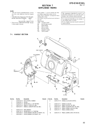
.... • Color Indication of Appearance Parts Example: KNOB, BALANCE (WHITE) . . . (RED) R R Parts of electrical parts list. • Abbreviation CND : Canadian model EE : East European model IT : Italian model KR : Korean model RU : Russian model SP : Singapore model TW : Taiwan model 7-1. HANDLE SECTION CFD-E100/E100L Ver. 1.1 The components identified by mark 0 or dotted line with part number specified. No. 1 2 3 4 4 5 6 7 7 Part No. Description 3-040-916-01 FOOT...
.... • Color Indication of Appearance Parts Example: KNOB, BALANCE (WHITE) . . . (RED) R R Parts of electrical parts list. • Abbreviation CND : Canadian model EE : East European model IT : Italian model KR : Korean model RU : Russian model SP : Singapore model TW : Taiwan model 7-1. HANDLE SECTION CFD-E100/E100L Ver. 1.1 The components identified by mark 0 or dotted line with part number specified. No. 1 2 3 4 4 5 6 7 7 Part No. Description 3-040-916-01 FOOT...

Service Manual
Page 55
... mark 0 or dotted line with part number specified. Les composants identifiés par une marque 0 sont critiques pour la sécurité. EE : East European model SP : Singapore model IT : Italian model TW : Taiwan model KR : Korean model RU : Russian model Remark Ref. SECTION 8 ELECTRICAL PARTS LIST CFD-E100/E100L Ver. 1.1 BATTERY 1 BATTERY 2 CD NOTE: • Due to standardization, replacements in the parts list may have some difference...
... mark 0 or dotted line with part number specified. Les composants identifiés par une marque 0 sont critiques pour la sécurité. EE : East European model SP : Singapore model IT : Italian model TW : Taiwan model KR : Korean model RU : Russian model Remark Ref. SECTION 8 ELECTRICAL PARTS LIST CFD-E100/E100L Ver. 1.1 BATTERY 1 BATTERY 2 CD NOTE: • Due to standardization, replacements in the parts list may have some difference...
Service Manual
Page 63
... 3-266-053-01 HEAD, RP (RECORD/PLAYBACK) LCD401 1-805-845-11 DISPLAY PANEL, LIQUID CRYSTAL M901 X-3385-048-1 MOTOR SUB ASSY (CAPSTAN/REEL) S902 1-762-819-11 SWITCH, LEAF (TAPE PLAY) SP101 1-826-150-11 SPEAKER (8cm) (L-ch) 1/10W 1/10W 1/10W (E100) SP201 1-826-150-11 SPEAKER (8cm) (R-ch) 0 T901 1-435-917-21 TRANSFORMER, POWER (US, CND, TW) 0 T901...
... 3-266-053-01 HEAD, RP (RECORD/PLAYBACK) LCD401 1-805-845-11 DISPLAY PANEL, LIQUID CRYSTAL M901 X-3385-048-1 MOTOR SUB ASSY (CAPSTAN/REEL) S902 1-762-819-11 SWITCH, LEAF (TAPE PLAY) SP101 1-826-150-11 SPEAKER (8cm) (L-ch) 1/10W 1/10W 1/10W (E100) SP201 1-826-150-11 SPEAKER (8cm) (R-ch) 0 T901 1-435-917-21 TRANSFORMER, POWER (US, CND, TW) 0 T901...


