Operating Instructions
Page 1
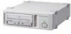
2-546-892-13(1) AIT Drive Operating Instructions AIT-2 Turbo TAPE DRIVE AITe200/AITe200T AIT-1 Turbo TAPE DRIVE AITe100/AITe100T AIT-E Turbo TAPE DRIVE AITe50/AITe50T ©2004 Sony Corporation
2-546-892-13(1) AIT Drive Operating Instructions AIT-2 Turbo TAPE DRIVE AITe200/AITe200T AIT-1 Turbo TAPE DRIVE AITe100/AITe100T AIT-E Turbo TAPE DRIVE AITe50/AITe50T ©2004 Sony Corporation
Operating Instructions
Page 2
Model No. Address: 16450 W. for Regulatory Compliance Your AITe200 is indicated on the model number label on the bottom. Your AITe100 and AITe50 are located on your drive along with part 15 of the FCC Rules. Operation is subject to Sony contact in the instruction manual. To avoid electrical shock, do not expose the unit to rain or moisture. If you call...
Model No. Address: 16450 W. for Regulatory Compliance Your AITe200 is indicated on the model number label on the bottom. Your AITe100 and AITe50 are located on your drive along with part 15 of the FCC Rules. Operation is subject to Sony contact in the instruction manual. To avoid electrical shock, do not expose the unit to rain or moisture. If you call...

Operating Instructions
Page 3
This device requires shielded interface cables to comply with the limits for a Class B digital device, pursuant to Part 15 of the following measures: • Reorient or relocate the receiving antenna. • Increase the separation between the equipment and receiver. • Connect the equipment into an outlet on this equipment must be easily accessible. CAUTION The mains plug on...
This device requires shielded interface cables to comply with the limits for a Class B digital device, pursuant to Part 15 of the following measures: • Reorient or relocate the receiving antenna. • Increase the separation between the equipment and receiver. • Connect the equipment into an outlet on this equipment must be easily accessible. CAUTION The mains plug on...
Operating Instructions
Page 6
... to normal operation. • When the unit exhibits a distinct change in a confined space, such as opening or removing covers may expose you to qualified service personnel. 6 Safety Regulations Do not attempt to service the unit yourself as a bookcase, or built-in the operating instructions. Refer to all servicing to dangerous voltage or other controls may fall, causing serious injury to a child...
... to normal operation. • When the unit exhibits a distinct change in a confined space, such as opening or removing covers may expose you to qualified service personnel. 6 Safety Regulations Do not attempt to service the unit yourself as a bookcase, or built-in the operating instructions. Refer to all servicing to dangerous voltage or other controls may fall, causing serious injury to a child...
Operating Instructions
Page 7
... Specifications (AITe200 28 Specifications (AITe100 29 Specifications (AITe50 30 7 Table of Cartridges 26 Use Precautions 26 Storage Precautions 26 Head Cleaning 27 How to Use this Guide 8 Part 1. Care and Maintenance Appendix About AIT Drives 9 Features ...9 Useable Cartridges 10 System Components 11 Part Names and Functions 12 Front Panel 12 Rear Panel 13 Supplied Items 14 Interconnections 14 SCSI ID Setting 15 Option Switches (DIP Switch 15 How to use the AIT Drive 18 Cartridge Removal...
... Specifications (AITe200 28 Specifications (AITe100 29 Specifications (AITe50 30 7 Table of Cartridges 26 Use Precautions 26 Storage Precautions 26 Head Cleaning 27 How to Use this Guide 8 Part 1. Care and Maintenance Appendix About AIT Drives 9 Features ...9 Useable Cartridges 10 System Components 11 Part Names and Functions 12 Front Panel 12 Rear Panel 13 Supplied Items 14 Interconnections 14 SCSI ID Setting 15 Option Switches (DIP Switch 15 How to use the AIT Drive 18 Cartridge Removal...

Operating Instructions
Page 8
... future reference. Part 2 describes the necessary connections between the drive and the host computer. Please read it carefully before using the unit, and keep it . If other SCSI devices are installing the drive. Refer to the parts that relate to change the SCSI ID setting. The Guide consists of each part. How to Use this Guide This Guide describes the AIT Drive Unit AITe200/AITe100/AITe50, and how to take care of the drive and cartridges, and...
... future reference. Part 2 describes the necessary connections between the drive and the host computer. Please read it carefully before using the unit, and keep it . If other SCSI devices are installing the drive. Refer to the parts that relate to change the SCSI ID setting. The Guide consists of each part. How to Use this Guide This Guide describes the AIT Drive Unit AITe200/AITe100/AITe50, and how to take care of the drive and cartridges, and...
Operating Instructions
Page 9
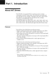
... an external AIT drive unit that uses data cartridges conforming to the AIT-E Turbo, AIT-1, and AIT-1 Turbo formats. • Data compression provides 104 gigabytes of storage on 186 m tape-length AIT-1 Turbo data cartridge.*1 The native capacity is 40 gigabytes of storage on 186 m tape-length AIT-2 Turbo data cartridge. • Ultra 160 Wide SCSI LVD/SE interface is fully supported for host computer access. *1 This is an external AIT drive unit that uses data cartridges conforming to the AIT-1 Turbo format. The AIT Drive Unit AITe100...
... an external AIT drive unit that uses data cartridges conforming to the AIT-E Turbo, AIT-1, and AIT-1 Turbo formats. • Data compression provides 104 gigabytes of storage on 186 m tape-length AIT-1 Turbo data cartridge.*1 The native capacity is 40 gigabytes of storage on 186 m tape-length AIT-2 Turbo data cartridge. • Ultra 160 Wide SCSI LVD/SE interface is fully supported for host computer access. *1 This is an external AIT drive unit that uses data cartridges conforming to the AIT-1 Turbo format. The AIT Drive Unit AITe100...

Operating Instructions
Page 10
... specifically for host computer access. *1 This is assuming 2.6:1 compression ratio. The AITe50 can damage the AIT drive. The AIT Drive Unit AITe50 has the following features: • Supports reading and writing to data cartridges conforming to the AIT-E Turbo format. • Data compression provides 52 gigabytes of storage on 98 m tape-length AIT-E Turbo data cartridge. • Wide Ultra SCSI LVD/SE interface is fully supported for AIT. • Do not use anything but AIT cartridges...
... specifically for host computer access. *1 This is assuming 2.6:1 compression ratio. The AITe50 can damage the AIT drive. The AIT Drive Unit AITe50 has the following features: • Supports reading and writing to data cartridges conforming to the AIT-E Turbo format. • Data compression provides 52 gigabytes of storage on 98 m tape-length AIT-E Turbo data cartridge. • Wide Ultra SCSI LVD/SE interface is fully supported for AIT. • Do not use anything but AIT cartridges...

Operating Instructions
Page 12
... Independent Tape Access in Progress (others) Independent Independent Cleaning is requested Independent Independent Cleaning is on /0.3 sec off ) Fast 1 pulse (0.3 sec on . 3 Dust Cover This cover protects the AIT data cartridge receptacle. 4 LED Indication for information on inserting and removing a AIT data cartridge. 2 POWER Indicator Lights while the drive is Not Completed Independent Independent Media Error Occurred H/W Error Occurred on Slow 1 pulse (0.9 sec on/0.3 sec off ) 12 Part 1. Introduction Part...
... Independent Tape Access in Progress (others) Independent Independent Cleaning is requested Independent Independent Cleaning is on /0.3 sec off ) Fast 1 pulse (0.3 sec on . 3 Dust Cover This cover protects the AIT data cartridge receptacle. 4 LED Indication for information on inserting and removing a AIT data cartridge. 2 POWER Indicator Lights while the drive is Not Completed Independent Independent Media Error Occurred H/W Error Occurred on Slow 1 pulse (0.9 sec on/0.3 sec off ) 12 Part 1. Introduction Part...

Operating Instructions
Page 13
Rear Panel 5 EJECT Button Push to remove a data cartridge from the drive. 6 POWER Switch Press to turn the drive on or off. 1 2 3 4 1 Rotary Selector Switch SCSI ID selector. 2 AC IN Connector Connect the supplied power cable here. 3 SCSI Connector Connects to the SCSI bus connector of the host computer or another SCSI peripheral or the terminator. 4 Cooling Fan 13 Part 1. Introduction
Rear Panel 5 EJECT Button Push to remove a data cartridge from the drive. 6 POWER Switch Press to turn the drive on or off. 1 2 3 4 1 Rotary Selector Switch SCSI ID selector. 2 AC IN Connector Connect the supplied power cable here. 3 SCSI Connector Connects to the SCSI bus connector of the host computer or another SCSI peripheral or the terminator. 4 Cooling Fan 13 Part 1. Introduction

Operating Instructions
Page 14
... of the SCSI bus, use less than 1.5 meter, if connected to the host computer, and select the SCSI ID with a half pitch 68 pin connector. Supplied Items When you have all of the required accessories for your supplier if anything is missing or broken. • AIT Drive Unit • Power Cable • Operating Instructions/Device Driver (CD-ROM) Interconnections The SCSI bus allows connection of...
... of the SCSI bus, use less than 1.5 meter, if connected to the host computer, and select the SCSI ID with a half pitch 68 pin connector. Supplied Items When you have all of the required accessories for your supplier if anything is missing or broken. • AIT Drive Unit • Power Cable • Operating Instructions/Device Driver (CD-ROM) Interconnections The SCSI bus allows connection of...

Operating Instructions
Page 15
... unit. Option Switches (DIP Switch) Remove the two slotted screws by the rotary switch on the SCSI bus. • When shipped from the factory, the SCSI ID is usually set to the following figure for the SCSI ID setting. Once the DIP switch settings have been changed, replace the access cover using the two original slotted screws provided. DIP Switch Access Cover Slotted Screws 15 Part 2. Be sure to connect...
... unit. Option Switches (DIP Switch) Remove the two slotted screws by the rotary switch on the SCSI bus. • When shipped from the factory, the SCSI ID is usually set to the following figure for the SCSI ID setting. Once the DIP switch settings have been changed, replace the access cover using the two original slotted screws provided. DIP Switch Access Cover Slotted Screws 15 Part 2. Be sure to connect...

Operating Instructions
Page 18
How to use the AIT drive, and how to use the AIT Drive 1 Press the POWER switch on the front panel. Operation This section describes how to handle data cartridges. The TAPE MOTION indicator lights. 3 Computer software controls the reading and writing of tapes. The POWER indicator should light, and the TAPE MOTION, CLEANING REQUEST, and REPLACE TAPE indicators should blink as the self-test is performed. 2 When the three indicators stop blinking, open the dust...
How to use the AIT drive, and how to use the AIT Drive 1 Press the POWER switch on the front panel. Operation This section describes how to handle data cartridges. The TAPE MOTION indicator lights. 3 Computer software controls the reading and writing of tapes. The POWER indicator should light, and the TAPE MOTION, CLEANING REQUEST, and REPLACE TAPE indicators should blink as the self-test is performed. 2 When the three indicators stop blinking, open the dust...
Operating Instructions
Page 20
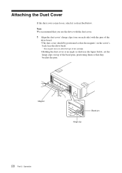
...that you use the drive with the dust cover. 1 Align the dust cover's hinge clips (one on each side) with the pins of the drive bezel. • The dust cover should be positioned so that the magnets* on the cover's back face the drive bezel. * This magnet does not affect the tape of the cartridge. •... Holding the dust cover at an angle as described below , set the hinge clips on top of the bezel pins, positioning them so that they bracket the pins. Attaching the Dust...
...that you use the drive with the dust cover. 1 Align the dust cover's hinge clips (one on each side) with the pins of the drive bezel. • The dust cover should be positioned so that the magnets* on the cover's back face the drive bezel. * This magnet does not affect the tape of the cartridge. •... Holding the dust cover at an angle as described below , set the hinge clips on top of the bezel pins, positioning them so that they bracket the pins. Attaching the Dust...
Operating Instructions
Page 22
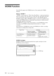
... on a tape only once, but permits that data to as a non-WORM drive when used with WORM logo) Read/Write Enabled Waiting for Eject Read/Write Enabled Read/ Append-Write Enabled WORM Cartridges WORM cartridges can not be read from regular cartridges by their WORM logo and red shutters. When a WORM cartridge is being used with an application that supports the...
... on a tape only once, but permits that data to as a non-WORM drive when used with WORM logo) Read/Write Enabled Waiting for Eject Read/Write Enabled Read/ Append-Write Enabled WORM Cartridges WORM cartridges can not be read from regular cartridges by their WORM logo and red shutters. When a WORM cartridge is being used with an application that supports the...
Operating Instructions
Page 23
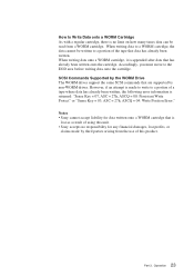
...: Write Position Error." When writing data to a WORM cartridge, the data cannot be read from the use of this unit. • Sony accepts no limit on how many times data can be written to a portion of the tape that are supported by non-WORM drives. How to Write Data onto a WORM Cartridge As with a regular cartridge, there is no responsibility for data written onto a WORM cartridge that...
...: Write Position Error." When writing data to a WORM cartridge, the data cannot be read from the use of this unit. • Sony accepts no limit on how many times data can be written to a portion of the tape that are supported by non-WORM drives. How to Write Data onto a WORM Cartridge As with a regular cartridge, there is no responsibility for data written onto a WORM cartridge that...

Operating Instructions
Page 26
... to write or read a tape. • When finished using the drive, remove the cartridge. Care and Maintenance If you do not need to write to the tape, move this switch to the write-protect position (in a car. 26 Part 4. Please do not need to or accidentally erased. Do not open the shutter by hand, as touching the tape may interfere with reading...
... to write or read a tape. • When finished using the drive, remove the cartridge. Care and Maintenance If you do not need to write to the tape, move this switch to the write-protect position (in a car. 26 Part 4. Please do not need to or accidentally erased. Do not open the shutter by hand, as touching the tape may interfere with reading...

Operating Instructions
Page 28
Appendix Specifications (AITe200) ■ Performance Storage Capacity Bit Error Rate Data Transfer Rate (TAPE) Burst Data Transfer Rate (SCSI) Initialize Time 208 GB compressed (with 186 m AIT-2 Turbo cartridge)*1 80 GB uncompressed (with 186 m AIT-2 Turbo cartridge) less than 10-17 12 MB/s uncompressed (with AIT-E Turbo, AIT-1 Turbo, AIT-2, and AIT-2 Turbo cartridge) 8 MB/s uncompressed (with AIT-1 cartridge) 12 MB/s maximum, asynchronous 160 MB/s maximum, synchronous less than 5 seconds ■ Operating Environment Operating Non-operating Temperature: 10 to 35°C (∆T
Appendix Specifications (AITe200) ■ Performance Storage Capacity Bit Error Rate Data Transfer Rate (TAPE) Burst Data Transfer Rate (SCSI) Initialize Time 208 GB compressed (with 186 m AIT-2 Turbo cartridge)*1 80 GB uncompressed (with 186 m AIT-2 Turbo cartridge) less than 10-17 12 MB/s uncompressed (with AIT-E Turbo, AIT-1 Turbo, AIT-2, and AIT-2 Turbo cartridge) 8 MB/s uncompressed (with AIT-1 cartridge) 12 MB/s maximum, asynchronous 160 MB/s maximum, synchronous less than 5 seconds ■ Operating Environment Operating Non-operating Temperature: 10 to 35°C (∆T
Operating Instructions
Page 29
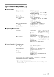
Specifications (AITe100) ■ Performance Storage Capacity Bit Error Rate Data Transfer Rate (TAPE) Burst Data Transfer Rate (SCSI) Initialize Time 104 GB compressed (with 186 m AIT-1 Turbo cartridge)*1 40 GB uncompressed (with 186 m AIT-1 Turbo cartridge) less than 10-17 6 MB/s uncompressed (with AIT-E Turbo and AIT-1 Turbo cartridge) 4 MB/s uncompressed (with AIT-1 cartridge) 12 MB/s maximum, asynchronous 40 MB/s maximum, synchronous less than 5 seconds ■ Operating Environment Operating Non-operating Temperature: 10 to 35°C (∆T
Specifications (AITe100) ■ Performance Storage Capacity Bit Error Rate Data Transfer Rate (TAPE) Burst Data Transfer Rate (SCSI) Initialize Time 104 GB compressed (with 186 m AIT-1 Turbo cartridge)*1 40 GB uncompressed (with 186 m AIT-1 Turbo cartridge) less than 10-17 6 MB/s uncompressed (with AIT-E Turbo and AIT-1 Turbo cartridge) 4 MB/s uncompressed (with AIT-1 cartridge) 12 MB/s maximum, asynchronous 40 MB/s maximum, synchronous less than 5 seconds ■ Operating Environment Operating Non-operating Temperature: 10 to 35°C (∆T

Operating Instructions
Page 30
Specifications (AITe50) ■ Performance Storage Capacity Bit Error Rate Data Transfer Rate (TAPE) Burst Data Transfer Rate (SCSI) Initialize Time 52 GB compressed (with 98 m AIT-E Turbo cartridge)*1 20 GB uncompressed (with 98 m AIT-E Turbo cartridge) less than 10-17 6 MB/s uncompressed 12 MB/s maximum, asynchronous 40 MB/s maximum, synchronous less than 5 seconds ■ Operating Environment Operating Non-operating Temperature: 10 to 35°C (∆T
Specifications (AITe50) ■ Performance Storage Capacity Bit Error Rate Data Transfer Rate (TAPE) Burst Data Transfer Rate (SCSI) Initialize Time 52 GB compressed (with 98 m AIT-E Turbo cartridge)*1 20 GB uncompressed (with 98 m AIT-E Turbo cartridge) less than 10-17 6 MB/s uncompressed 12 MB/s maximum, asynchronous 40 MB/s maximum, synchronous less than 5 seconds ■ Operating Environment Operating Non-operating Temperature: 10 to 35°C (∆T
