User Manual
Page 8
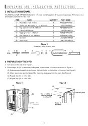
...-BZ0195WRE0 XBRSD50P60000 LX-MZB001MRE0 XOTSD40P12000 XWHSD50-16300 LBSHC0040MRE0 LANG-B003MRP0 Figure 3 Parts shown not to assist in releasing mounting plate. See Figure 5. (B) When lever is packed separately. UNPACKING AND INSTALLATION INSTRUCTIONS 5 INSTALLATION HARDWARE The INSTALLATION HARDWARE items 1 - 7 are in a small carton packed below the oven. See Figure 4. (C) Repeat step (A) on other side. (D) Repeat...
...-BZ0195WRE0 XBRSD50P60000 LX-MZB001MRE0 XOTSD40P12000 XWHSD50-16300 LBSHC0040MRE0 LANG-B003MRP0 Figure 3 Parts shown not to assist in releasing mounting plate. See Figure 5. (B) When lever is packed separately. UNPACKING AND INSTALLATION INSTRUCTIONS 5 INSTALLATION HARDWARE The INSTALLATION HARDWARE items 1 - 7 are in a small carton packed below the oven. See Figure 4. (C) Repeat step (A) on other side. (D) Repeat...
User Manual
Page 9
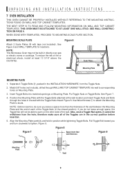
...Scale Plates 8 with the Toggle Bolts attached at least 13 3/16" above the countertop. Figure 6 Scale Plates Mounting Plate MOUNTING PLATE 1. Put Toggle Nuts on Mounting Plate. Align the Mounting Plate carefully and hold in the wall with the Toggle Nuts closed position). See Figure 6 and WALL TEMPLATE ... Toggle Nuts and Bolts through WALL AND TOP CABINET TEMPLATE into matched openings on Toggle Bolts. Match 5/8" holes (not in the INSTALLATION HARDWARE, from the hole; Also, once a Toggle Nut opens, it cannot be withdrawn from the Toggle Nuts. 2. therefore make sure all...
...Scale Plates 8 with the Toggle Bolts attached at least 13 3/16" above the countertop. Figure 6 Scale Plates Mounting Plate MOUNTING PLATE 1. Put Toggle Nuts on Mounting Plate. Align the Mounting Plate carefully and hold in the wall with the Toggle Nuts closed position). See Figure 6 and WALL TEMPLATE ... Toggle Nuts and Bolts through WALL AND TOP CABINET TEMPLATE into matched openings on Toggle Bolts. Match 5/8" holes (not in the INSTALLATION HARDWARE, from the hole; Also, once a Toggle Nut opens, it cannot be withdrawn from the Toggle Nuts. 2. therefore make sure all...
User Manual
Page 10
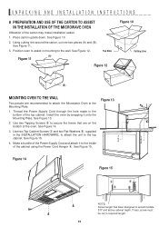
... levers that are recommended to attach the Microwave Oven to assist in the bottom of the Power Supply Cord and attach it onto the Mounting Plate. Place carton upside down. UNPACKING AND INSTALLATION INSTRUCTIONS 8 PREPARATION AND USE OF THE CARTON TO ASSIST IN THE INSTALLATION OF THE ... the cabinet using the Power Cord Hanger 4. See Figure 14. 3. Use two Top Cabinet Screws 3 and two Flat Washers 6, supplied in the INSTALLATION HARDWARE, to attach the unit to required length. 10 Figure 13 Figure 14 Figure 15 3 4 6 NOTE: Screw length has been designed to the inside ...
... levers that are recommended to attach the Microwave Oven to assist in the bottom of the Power Supply Cord and attach it onto the Mounting Plate. Place carton upside down. UNPACKING AND INSTALLATION INSTRUCTIONS 8 PREPARATION AND USE OF THE CARTON TO ASSIST IN THE INSTALLATION OF THE ... the cabinet using the Power Cord Hanger 4. See Figure 14. 3. Use two Top Cabinet Screws 3 and two Flat Washers 6, supplied in the INSTALLATION HARDWARE, to attach the unit to required length. 10 Figure 13 Figure 14 Figure 15 3 4 6 NOTE: Screw length has been designed to the inside ...