

Instructions for Use
Page 53
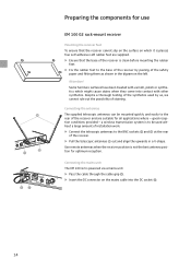
...ቢ Display for the current channel bank "1 ... 8, U" ባ Display for the current channel number "1 ... 4" ቤ "B.CH" - Overview of operating controls EM 100 G2 rack-mount receiver ³ · »¿ ´ ቢ ባቤ ብ ቦቧ ቨ ቩቪ ቫ ቭቮ ¹...; ̆ button (UP) » ̄ button (DOWN) ¿ SET button ´ POWER button (serves as the ESC (cancel) key in the operating menu) ² Cable grip for power supply DC cable ¶ DC socket for connection of mains unit (DC IN) º Audio output (...
...ቢ Display for the current channel bank "1 ... 8, U" ባ Display for the current channel number "1 ... 4" ቤ "B.CH" - Overview of operating controls EM 100 G2 rack-mount receiver ³ · »¿ ´ ቢ ባቤ ብ ቦቧ ቨ ቩቪ ቫ ቭቮ ¹...; ̆ button (UP) » ̄ button (DOWN) ¿ SET button ´ POWER button (serves as the ESC (cancel) key in the operating menu) ² Cable grip for power supply DC cable ¶ DC socket for connection of mains unit (DC IN) º Audio output (...
Instructions for Use
Page 61
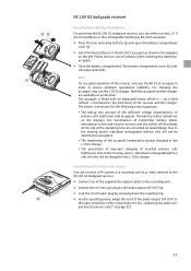
... for optimum reception. Use remote antennas when the receiver position is to be mounted quickly and easily to the rear of the receiver and are supplied. ̈ Ensure that the base of the receiver is clean before mounting the rubber feet. ̈ Fix the rubber feet to the BNC sockets ¸... cannot slip on the surface on which might cause stains when they come into the DC socket ¶. 14 Connecting the mains unit The EM 100 G2 is powered via a mains unit. ̈ Pass the cable through the cable grip ². ̈ Insert the DC connector on the left. Despite a thorough testing of...
... for optimum reception. Use remote antennas when the receiver position is to be mounted quickly and easily to the rear of the receiver and are supplied. ̈ Ensure that the base of the receiver is clean before mounting the rubber feet. ̈ Fix the rubber feet to the BNC sockets ¸... cannot slip on the surface on which might cause stains when they come into the DC socket ¶. 14 Connecting the mains unit The EM 100 G2 is powered via a mains unit. ̈ Pass the cable through the cable grip ². ̈ Insert the DC connector on the left. Despite a thorough testing of...
Instructions for Use
Page 64
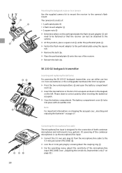
...also not be identified as accessories. Connecting units to ensure optimum operational reliability. video camera) to the EK 100 G2 bodypack receiver. ̈ Connect one of the supplied line output cables to the recording unit. ̈ Connect the 3.5 mm jack plug to the input ...;¾ º ³ EK 100 G2 bodypack receiver Inserting and replacing the batteries For powering the EK 100 G2 bodypack receiver, you can connect a PA system or a recording unit (e.g. For charging the accupack, only use two 1.5 V AA size batteries or the rechargeable Sennheiser BA 2015 accupack. ̈ Press ...
...also not be identified as accessories. Connecting units to ensure optimum operational reliability. video camera) to the EK 100 G2 bodypack receiver. ̈ Connect one of the supplied line output cables to the recording unit. ̈ Connect the 3.5 mm jack plug to the input ...;¾ º ³ EK 100 G2 bodypack receiver Inserting and replacing the batteries For powering the EK 100 G2 bodypack receiver, you can connect a PA system or a recording unit (e.g. For charging the accupack, only use two 1.5 V AA size batteries or the rechargeable Sennheiser BA 2015 accupack. ̈ Press ...
Instructions for Use
Page 65
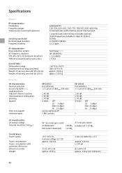
... transmitter Inserting and replacing the batteries For powering the SK 100 G2 bodypack transmitter, you can best be fastened so that the receiver can either use two 1.5 V AA size batteries or the rechargeable Sennheiser BA 2015 accupack. ̈ Press the two unlocking buttons ᕩ and open the battery ... battery compartment. Ƹ ¹ ƹ º¾ º Ƹ ƹ³ 18 Mounting the bodypack receiver to a camera Use the supplied camera kit to mount the receiver to be attached to the camera. ̈ At this position, place a square nut ƹ under the perforated plate ...
... transmitter Inserting and replacing the batteries For powering the SK 100 G2 bodypack transmitter, you can best be fastened so that the receiver can either use two 1.5 V AA size batteries or the rechargeable Sennheiser BA 2015 accupack. ̈ Press the two unlocking buttons ᕩ and open the battery ... battery compartment. Ƹ ¹ ƹ º¾ º Ƹ ƹ³ 18 Mounting the bodypack receiver to a camera Use the supplied camera kit to mount the receiver to be attached to the camera. ̈ At this position, place a square nut ƹ under the perforated plate ...
Instructions for Use
Page 89
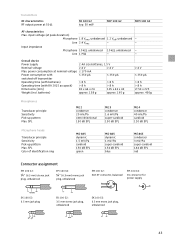
... ≤± 15 ppm Sennheiser HDX 40-18,000 Hz ≥ 110 dB(A) ≤ 0.9 % -10 °C to +55 °C 380 x 370 x 70 approx. 3100 g approx. 2160 g Receivers RF characteristics Receiver principle Sensitivity (with HDX, peak deviation) Adjacent channel rejection Intermodulation attenuation Blocking Squelch Pilot tone squelch Antenna inputs EM 100 G2 true diversity
... ≤± 15 ppm Sennheiser HDX 40-18,000 Hz ≥ 110 dB(A) ≤ 0.9 % -10 °C to +55 °C 380 x 370 x 70 approx. 3100 g approx. 2160 g Receivers RF characteristics Receiver principle Sensitivity (with HDX, peak deviation) Adjacent channel rejection Intermodulation attenuation Blocking Squelch Pilot tone squelch Antenna inputs EM 100 G2 true diversity
Instructions for Use
Page 90
... 144 dB SPL red Connector assignment EM 100 G2: ¼'' (6.3 mm) stereo jack plug, unbalanced EM 100 G2: ¼'' (6.3 mm) mono jack plug, unbalanced NC/GN D SK 100 G2: 3.5 mm jack plug EK 100 G2: 3.5 mm stereo jack plug, unbalanced EM 100 G2: XLR-3F connector, balanced + 21 3 EM 100 G2: DC connector for power supply EK 100 G2: 3.5 mm mono jack plug, unbalanced 43 Input...
... 144 dB SPL red Connector assignment EM 100 G2: ¼'' (6.3 mm) stereo jack plug, unbalanced EM 100 G2: ¼'' (6.3 mm) mono jack plug, unbalanced NC/GN D SK 100 G2: 3.5 mm jack plug EK 100 G2: 3.5 mm stereo jack plug, unbalanced EM 100 G2: XLR-3F connector, balanced + 21 3 EM 100 G2: DC connector for power supply EK 100 G2: 3.5 mm mono jack plug, unbalanced 43 Input...
