
Instructions for Use
Page 1
Active Antenna Splitter 2 x 1:8 ASA 3000 Instructions for use 1
Active Antenna Splitter 2 x 1:8 ASA 3000 Instructions for use 1

Instructions for Use
Page 2
...) can be exchanged for a selective input module. The active antenna splitter allows you to make receiver systems with only one pair of application: y Multi-channel RF installations (fixed or mobile) y Permanent installations in antenna boosters, the signals are routed without loss the the connected receivers. Areas of diversity antennas. Contents Safety information 3 Delivery includes 3 Operating elements 4 Connection diagram 5 Trouble shooting 9 Accessories 10 Specifications 11 Manufacturer declarations 12 Brief description...
...) can be exchanged for a selective input module. The active antenna splitter allows you to make receiver systems with only one pair of application: y Multi-channel RF installations (fixed or mobile) y Permanent installations in antenna boosters, the signals are routed without loss the the connected receivers. Areas of diversity antennas. Contents Safety information 3 Delivery includes 3 Operating elements 4 Connection diagram 5 Trouble shooting 9 Accessories 10 Specifications 11 Manufacturer declarations 12 Brief description...
Instructions for Use
Page 3
... y 1 active antenna splitter, 2 x 1:8 y 1 mains cable y 1 rack-mounting kit y 1 set up the unit on an even surface or mount it into a rack! Make sure that no-one can stumble over them! Keep the unit away from the unit! Lay the cables in breach of self-adhesive plastic feet y 2 telescopic antennas y 1 instruction manual For accessories, please refer to AC outlets. Keep liquids and small parts which conduct...
... y 1 active antenna splitter, 2 x 1:8 y 1 mains cable y 1 rack-mounting kit y 1 set up the unit on an even surface or mount it into a rack! Make sure that no-one can stumble over them! Keep the unit away from the unit! Lay the cables in breach of self-adhesive plastic feet y 2 telescopic antennas y 1 instruction manual For accessories, please refer to AC outlets. Keep liquids and small parts which conduct...
Instructions for Use
Page 4
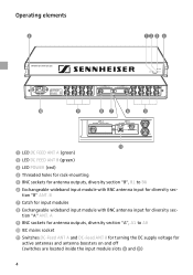
...for antenna outputs, diversity section "A", A1 to B8 ² Exchangeable wideband input module with BNC antenna input for diversity sec- B ¶ Catch for input modules º Exchangeable wideband input module with BNC antenna input for diversity sec- Operating elements...POWER (red) ¿ Threaded holes for rack-mounting ´ BNC sockets for antenna outputs, diversity section "B", B1 to A8 µ IEC mains socket ¸ Switches DC-Feed ANT A and DC-Feed ANT B for turning the DC supply voltage for active antennas and antenna boosters on and off (switches are located inside the input...
...for antenna outputs, diversity section "A", A1 to B8 ² Exchangeable wideband input module with BNC antenna input for diversity sec- B ¶ Catch for input modules º Exchangeable wideband input module with BNC antenna input for diversity sec- Operating elements...POWER (red) ¿ Threaded holes for rack-mounting ´ BNC sockets for antenna outputs, diversity section "B", B1 to A8 µ IEC mains socket ¸ Switches DC-Feed ANT A and DC-Feed ANT B for turning the DC supply voltage for active antennas and antenna boosters on and off (switches are located inside the input...
Instructions for Use
Page 5
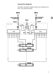
AB 1036 Input A 1 : 8 1 : 8 ANT B POWER ANT A 8 7 6 5 4 3 2 1 12 345678 EM 3000 1 B A EM 3000 2 B A EM 3000 8 B A 5 AB 1036 Input B ASA 3000 Mains Antenna booster e.g. ANT B ANT A Antenna booster e.g. or 16-channel system. Connection diagram The below connection diagram shows the connections for an 8-
AB 1036 Input A 1 : 8 1 : 8 ANT B POWER ANT A 8 7 6 5 4 3 2 1 12 345678 EM 3000 1 B A EM 3000 2 B A EM 3000 8 B A 5 AB 1036 Input B ASA 3000 Mains Antenna booster e.g. ANT B ANT A Antenna booster e.g. or 16-channel system. Connection diagram The below connection diagram shows the connections for an 8-
Instructions for Use
Page 6
... ASA 3000 is suitable for active antennas or antenna boosters turned on. The two LEDs DC FEED ANT A ³ and DC FEED ANT B · light up green. · 6 Connecting the antennas ̈ You can be mounted into a rack. ̈ Fix the unit to the BNC sockets ᕦ and º of the synthetics used by using the supplied rackmounting kit. ̈ To set up the unit on...
... ASA 3000 is suitable for active antennas or antenna boosters turned on. The two LEDs DC FEED ANT A ³ and DC FEED ANT B · light up green. · 6 Connecting the antennas ̈ You can be mounted into a rack. ̈ Fix the unit to the BNC sockets ᕦ and º of the synthetics used by using the supplied rackmounting kit. ̈ To set up the unit on...

Instructions for Use
Page 7
... 3031, or eight twin receivers, e.g. To do so, remove the two input modu- Note: µ The ASA 3000 can be turned off. If you use passive antennas only, the DC supply voltage can be connected. ̈ Use BNC cables to connect the receivers to the BNC sockets ´ and ¾ as it is connected to B1. The ASA 3000 has no power switch. The unit is fitted with 100...
... 3031, or eight twin receivers, e.g. To do so, remove the two input modu- Note: µ The ASA 3000 can be turned off. If you use passive antennas only, the DC supply voltage can be connected. ̈ Use BNC cables to connect the receivers to the BNC sockets ´ and ¾ as it is connected to B1. The ASA 3000 has no power switch. The unit is fitted with 100...
Instructions for Use
Page 8
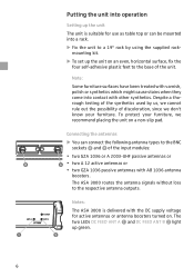
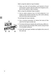
... BNC connector. ̈ Insert the new input modules and tighten the screw of the selective input modules! GZA 1036 antenna with antenna booster (e.g. ¶ º¶ When using the wideband input modules: y Use an active antenna (e.g. A 12 AD antenna) or an antenna with AB 1036 antenna booster). When using the selective input modules: y Make sure that all transmitters and receivers of your transmission system operate within the frequency window of...
... BNC connector. ̈ Insert the new input modules and tighten the screw of the selective input modules! GZA 1036 antenna with antenna booster (e.g. ¶ º¶ When using the wideband input modules: y Use an active antenna (e.g. A 12 AD antenna) or an antenna with AB 1036 antenna booster). When using the selective input modules: y Make sure that all transmitters and receivers of your transmission system operate within the frequency window of...
Instructions for Use
Page 9
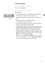
... LED POWER » does not light up green. Disturbed reception or no reception Possible causes: y Transmitting antennas are not within the frequency window of the selective input modules (optional) and antenna boosters (optional) y When using active antennas or antenna boosters, the supply voltage must be turned on (see "Connecting the antennas" on y Transmitter batteries are not inserted or batteries are ¸ low y The antennas are not connected correctly y The connecting cables...
... LED POWER » does not light up green. Disturbed reception or no reception Possible causes: y Transmitting antennas are not within the frequency window of the selective input modules (optional) and antenna boosters (optional) y When using active antennas or antenna boosters, the supply voltage must be turned on (see "Connecting the antennas" on y Transmitter batteries are not inserted or batteries are ¸ low y The antennas are not connected correctly y The connecting cables...
Instructions for Use
Page 10
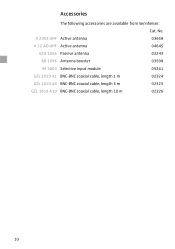
A 2003 UHF Active antenna 03658 A 12 AD UHF Active antenna 04645 GZA 1036 Passive antenna 02243 AB 1036 Antenna booster 03598 IM 3000 Selective input module 05241 GZL 1019 A1 BNC-BNC coaxial cable, length 1 m 02324 GZL 1019 A5 BNC-BNC coaxial cable, length 5 m 02325 GZL 1019 A10 BNC-BNC coaxial cable, length 10 m 02326 10 No. Accessories The following accessories are available from Sennheiser: Cat.
A 2003 UHF Active antenna 03658 A 12 AD UHF Active antenna 04645 GZA 1036 Passive antenna 02243 AB 1036 Antenna booster 03598 IM 3000 Selective input module 05241 GZL 1019 A1 BNC-BNC coaxial cable, length 1 m 02324 GZL 1019 A5 BNC-BNC coaxial cable, length 5 m 02325 GZL 1019 A10 BNC-BNC coaxial cable, length 10 m 02326 10 No. Accessories The following accessories are available from Sennheiser: Cat.
Instructions for Use
Page 11
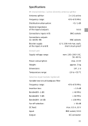
... / active diversity antenna splitter Antenna splitter: 2 x 1:8, active Frequency range: 470-870 MHz Distribution attenuation: +3/-1 dB Nominal impedance of the inputs/outputs: 50 Ω Connections inputs A/B: BNC sockets Connections outputs A1-A8/B1-B8: BNC sokkets Booster supply at the inputs A and B: 12 V, 200 mA max. each, short circuit-proof Overall unit Supply voltage range: Power consumption: Weight: Dimensions: Temperature range: nom. 100-240 V AC, 50-60 Hz...
... / active diversity antenna splitter Antenna splitter: 2 x 1:8, active Frequency range: 470-870 MHz Distribution attenuation: +3/-1 dB Nominal impedance of the inputs/outputs: 50 Ω Connections inputs A/B: BNC sockets Connections outputs A1-A8/B1-B8: BNC sokkets Booster supply at the inputs A and B: 12 V, 200 mA max. each, short circuit-proof Overall unit Supply voltage range: Power consumption: Weight: Dimensions: Temperature range: nom. 100-240 V AC, 50-60 Hz...

Instructions for Use
Page 12
... into operation, please observe the respective country-specific regulations! 12 provided that the sales receipt be claimed in compliance with the product; due to the responsible service partner. The guarantee can be retained as proof of purchase. Depending on our choice, guarantee service comprises, free of charge, the removal of material and manufacturing defects through repair or replacement...
... into operation, please observe the respective country-specific regulations! 12 provided that the sales receipt be claimed in compliance with the product; due to the responsible service partner. The guarantee can be retained as proof of purchase. Depending on our choice, guarantee service comprises, free of charge, the removal of material and manufacturing defects through repair or replacement...

Instructions for Use
Page 13
Sennheiser electronic GmbH & Co. KG 30900 Wedemark, Germany www.sennheiser.com Printed in Germany Publ. 05/07 093248 / A03
Sennheiser electronic GmbH & Co. KG 30900 Wedemark, Germany www.sennheiser.com Printed in Germany Publ. 05/07 093248 / A03


