
Instructions for Use
Page 53
Contents Contents Important safety instructions 2 The AC 3200 active transmitter combiner 8:1 5 Delivery includes 5 Connection diagram 6 Product overview 7 Putting the AC 3200 into operation 8 Preparing the AC 3200 for use 8 Connecting the antenna 10 Connecting a transmitter to the AC 3200 10 Connecting the mains cable 11 Switching the AC 3200 on and off 11 Recommendations and tips for optimum reception 12 Cleaning the AC 3200 12 If a problem occurs 13 Accessories and spare parts 14 Specifications 15 Manufacturer Declarations 16 1
Contents Contents Important safety instructions 2 The AC 3200 active transmitter combiner 8:1 5 Delivery includes 5 Connection diagram 6 Product overview 7 Putting the AC 3200 into operation 8 Preparing the AC 3200 for use 8 Connecting the antenna 10 Connecting a transmitter to the AC 3200 10 Connecting the mains cable 11 Switching the AC 3200 on and off 11 Recommendations and tips for optimum reception 12 Cleaning the AC 3200 12 If a problem occurs 13 Accessories and spare parts 14 Specifications 15 Manufacturer Declarations 16 1
Instructions for Use
Page 54
.... 18. Heed all servicing to qualified service personnel. The device should be connected to avoid injury from the AC receptacle. 16. Only use caution when moving the cart/apparatus combination to properly grounded power outlets. 10. Refer...inside, the device has been exposed to rain or moisture. 17. To completely disconnect the device from the AC mains, disconnect the mains plug from tip-over. 13. WARNING: To reduce the risk of the mains ...only with the cart, stand, tripod, bracket, or table specified by Sennheiser. 12. Do not expose the device to third parties. 3.
.... 18. Heed all servicing to qualified service personnel. The device should be connected to avoid injury from the AC receptacle. 16. Only use caution when moving the cart/apparatus combination to properly grounded power outlets. 10. Refer...inside, the device has been exposed to rain or moisture. 17. To completely disconnect the device from the AC mains, disconnect the mains plug from tip-over. 13. WARNING: To reduce the risk of the mains ...only with the cart, stand, tripod, bracket, or table specified by Sennheiser. 12. Do not expose the device to third parties. 3.
Instructions for Use
Page 55
... shock. The symbols on the left is attached to determine that may be sure the service technician has used replacement parts specified by Sennheiser or those having the same characteristics as this may result in a safe operating condition. 3 Important safety instructions Hazard warnings on the rear ... on this label have the following meaning: This symbol is intended to alert the user to the presence of uninsulated dangerous voltage within the AC 3200's enclosure that the device is in fire, electric shock, or other hazards. Safety check Upon completion of any service or repairs to this...
... shock. The symbols on the left is attached to determine that may be sure the service technician has used replacement parts specified by Sennheiser or those having the same characteristics as this may result in a safe operating condition. 3 Important safety instructions Hazard warnings on the rear ... on this label have the following meaning: This symbol is intended to alert the user to the presence of uninsulated dangerous voltage within the AC 3200's enclosure that the device is in fire, electric shock, or other hazards. Safety check Upon completion of any service or repairs to this...

Instructions for Use
Page 56
"Improper use of the AC 3200 includes: y using the device for professional purposes, y having read this instruction manual especially the chapter "Important safety instructions" on page 2, y using the device other than as described in this instruction manual, or under operating conditions which differ from those described herein. 4 Important safety instructions Intended use of the device Intended use " means using the device within the operating conditions and limitations described in this instruction manual.
"Improper use of the AC 3200 includes: y using the device for professional purposes, y having read this instruction manual especially the chapter "Important safety instructions" on page 2, y using the device other than as described in this instruction manual, or under operating conditions which differ from those described herein. 4 Important safety instructions Intended use of the device Intended use " means using the device within the operating conditions and limitations described in this instruction manual.
Instructions for Use
Page 57
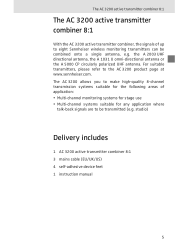
...systems suitable for the following areas of up to eight Sennheiser wireless monitoring transmitters can be transmitted (e.g. For suitable transmitters, please refer to be combined onto a single antenna, e.g. The AC 3200 allows you to make high-quality 8-channel transmission systems ...suitable for any application where talk-back signals are to the AC 3200 product page at www.sennheiser.com. studio) Delivery includes 1 AC 3200 active transmitter combiner 8:1 3 mains cable (EU/UK/US) 4 self-adhesive device feet 1 instruction manual ...
...systems suitable for the following areas of up to eight Sennheiser wireless monitoring transmitters can be transmitted (e.g. For suitable transmitters, please refer to be combined onto a single antenna, e.g. The AC 3200 allows you to make high-quality 8-channel transmission systems ...suitable for any application where talk-back signals are to the AC 3200 product page at www.sennheiser.com. studio) Delivery includes 1 AC 3200 active transmitter combiner 8:1 3 mains cable (EU/UK/US) 4 self-adhesive device feet 1 instruction manual ...
Instructions for Use
Page 58
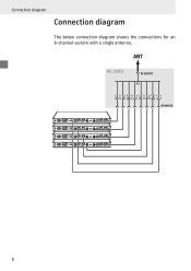
AC 3200 6 Connection diagram Connection diagram The below connection diagram shows the connections for an 8-channel system with a single antenna.
AC 3200 6 Connection diagram Connection diagram The below connection diagram shows the connections for an 8-channel system with a single antenna.
Instructions for Use
Page 60
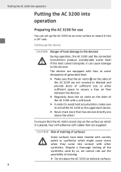
...The devices are equipped with fans to assist dissipation of generated heat: ̈ Make sure that the AC 3200 cannot slip on the surface on the sides of the AC 3200 with other ! To ensure that the air vents · on the sides of sufficient size or allow...above the other synthetics. During operation, the AC 3200 and the connected transmitters produce considerable waste heat! Putting the AC 3200 into operation Putting the AC 3200 into operation Preparing the AC 3200 for use You can cause damage to the devices! Setting up the AC 3200 on delicate surfaces. 8 Despite a thorough ...
...The devices are equipped with fans to assist dissipation of generated heat: ̈ Make sure that the AC 3200 cannot slip on the surface on the sides of the AC 3200 with other ! To ensure that the air vents · on the sides of sufficient size or allow...above the other synthetics. During operation, the AC 3200 and the connected transmitters produce considerable waste heat! Putting the AC 3200 into operation Putting the AC 3200 into operation Preparing the AC 3200 for use You can cause damage to the devices! Setting up the AC 3200 on delicate surfaces. 8 Despite a thorough ...
Instructions for Use
Page 61
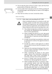
...accumulate, thereby exceeding the allowable limit value. If necessary, provide additional ventilation. ̈ In order to avoid heat accumulation, make sure to install the AC 3200 as the uppermost device in a rack, take good care not to affect the ventilation required for a duct or vent space of 1 U above the...loading and the electrical potentials will be different from those of devices which are not mounted into operation ̈ Ensure that the base of the AC 3200 is clean and free from grease before fitting the rubber feet. ̈ Fix the rubber feet to the base of the device by peeling...
...accumulate, thereby exceeding the allowable limit value. If necessary, provide additional ventilation. ̈ In order to avoid heat accumulation, make sure to install the AC 3200 as the uppermost device in a rack, take good care not to affect the ventilation required for a duct or vent space of 1 U above the...loading and the electrical potentials will be different from those of devices which are not mounted into operation ̈ Ensure that the base of the AC 3200 is clean and free from grease before fitting the rubber feet. ̈ Fix the rubber feet to the base of the device by peeling...
Instructions for Use
Page 62
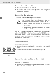
... the antenna using four screws (not included). Connecting the antenna CAUTION! The AC 3200 active transmitter combiner can be used with no distribution attenuation. Putting the AC 3200 into operation To mount the AC 3200 into a 19" rack: ̈ Slide the AC 3200 into the 19" rack. ̈ Secure the rack mount "ears" ... a low-attenuation 50 Ω coaxial cable. ̈ Connect the coaxial cable to the antenna output º. º Connecting a transmitter to the AC 3200 To connect a transmitter: ̈ Connect the BNC cable of the transmitter to one of the eight RF inputs RF IN 1 to RF IN 8 ...
... the antenna using four screws (not included). Connecting the antenna CAUTION! The AC 3200 active transmitter combiner can be used with no distribution attenuation. Putting the AC 3200 into operation To mount the AC 3200 into a 19" rack: ̈ Slide the AC 3200 into the 19" rack. ̈ Secure the rack mount "ears" ... a low-attenuation 50 Ω coaxial cable. ̈ Connect the coaxial cable to the antenna output º. º Connecting a transmitter to the AC 3200 To connect a transmitter: ̈ Connect the BNC cable of the transmitter to one of the eight RF inputs RF IN 1 to RF IN 8 ...

Instructions for Use
Page 63
...connected to any mains power supply with 100 V to 240 V AC (50 to the mains. Switching the AC 3200 on and off ̈ Press the on the channels where transmission power is in standby mode. Note: After switch-off . The AC 3200 switches off and the LED ¿ lights up on /off ...switch ´ again. RF indicators The AC 3200 has eight control LED » which light up red. ¿ goes off , the AC 3200 is available. 11 ¶ 70 W Putting the AC 3200 into operation ¶ ¶ ¶ 70 W ᕦ » ¿´ Connecting the ...
...connected to any mains power supply with 100 V to 240 V AC (50 to the mains. Switching the AC 3200 on and off ̈ Press the on the channels where transmission power is in standby mode. Note: After switch-off . The AC 3200 switches off and the LED ¿ lights up on /off ...switch ´ again. RF indicators The AC 3200 has eight control LED » which light up red. ¿ goes off , the AC 3200 is available. 11 ¶ 70 W Putting the AC 3200 into operation ¶ ¶ ¶ 70 W ᕦ » ¿´ Connecting the ...
Instructions for Use
Page 64
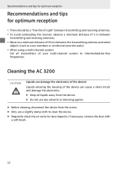
... mains. ̈ Only use a slightly damp cloth to intermodulation-free frequencies. Recommendations and tips for optimum reception Recommendations and tips for dust deposits. Cleaning the AC 3200 CAUTION! y To avoid overloading the receiver, observe a minimum distance of the device!
... mains. ̈ Only use a slightly damp cloth to intermodulation-free frequencies. Recommendations and tips for optimum reception Recommendations and tips for dust deposits. Cleaning the AC 3200 CAUTION! y To avoid overloading the receiver, observe a minimum distance of the device!
Instructions for Use
Page 65
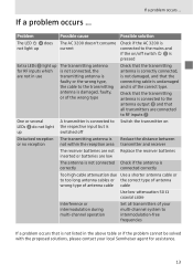
...is connected to the respective input but is switched off switch ´ is pressed Extra LEDs » light up The AC 3200 doesn't consume current Check if the AC 3200 is connected to the mains and if the on/off Switch the transmitter on Disturbed reception The transmitting antenna is Reduce ...batteries inserted or batteries are not in the above table or if the problem cannot be solved with the proposed solutions, please contact your local Sennheiser agent for assistance. 13 If a problem occurs ... Check that the transmitting antenna is connected to the antenna output º and that ...
...is connected to the respective input but is switched off switch ´ is pressed Extra LEDs » light up The AC 3200 doesn't consume current Check if the AC 3200 is connected to the mains and if the on/off Switch the transmitter on Disturbed reception The transmitting antenna is Reduce ...batteries inserted or batteries are not in the above table or if the problem cannot be solved with the proposed solutions, please contact your local Sennheiser agent for assistance. 13 If a problem occurs ... Check that the transmitting antenna is connected to the antenna output º and that ...

Instructions for Use
Page 67
...) RF input power nominal value up to 100 mW per input inputs protected up to max. 250 mW Impedance 50 Ω Power supply 100 V - 240 V AC, 50 - 60 Hz Power consumption max. 70 W Temperature range 0 °C to 45 °C Weight approx. 4 kg Type approvals Area USA: Canada: EU: Conformity FCC-Part...
...) RF input power nominal value up to 100 mW per input inputs protected up to max. 250 mW Impedance 50 Ω Power supply 100 V - 240 V AC, 50 - 60 Hz Power consumption max. 70 W Temperature range 0 °C to 45 °C Weight approx. 4 kg Type approvals Area USA: Canada: EU: Conformity FCC-Part...