
Technical Guide
Page 1
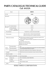
No. Silver Oxide Battery SB-AP (SR927SW) 1.55 V Approximately 4 years Nil. Movement SEIKO 6A32A Movement Outside diameter size (mm) Casing diameter Height ( Including battery portion ) Time indication Ø 27.8 Ø 27.3 3.69 3 hands (hour, ...Electronic circuit reset switch ● Battery life indicator Free Date, month, year adjustments (by quartz tester Battery Battery No. PARTS CATALOGUE /TECHNICAL GUIDE Cal. 6A32A Brand Cal. Voltage Battery life Jewels ● Fully automatic calendar (No calendar adjustment required at the end of a month, nor for a leap year)...
No. Silver Oxide Battery SB-AP (SR927SW) 1.55 V Approximately 4 years Nil. Movement SEIKO 6A32A Movement Outside diameter size (mm) Casing diameter Height ( Including battery portion ) Time indication Ø 27.8 Ø 27.3 3.69 3 hands (hour, ...Electronic circuit reset switch ● Battery life indicator Free Date, month, year adjustments (by quartz tester Battery Battery No. PARTS CATALOGUE /TECHNICAL GUIDE Cal. 6A32A Brand Cal. Voltage Battery life Jewels ● Fully automatic calendar (No calendar adjustment required at the end of a month, nor for a leap year)...
Technical Guide
Page 2
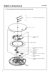
PARTS CATALOGUE ● Order of disassembly for the hands, dial and wheels on the back side Cal. 6A32A 1 HOUR, MINUTE AND SECOND HANDS 2 DIAL 3 DATE DIAL GUARD 0808 051 4 DATE DIAL 5 INTERMEDIATE 24-HOUR WHEEL 0817 046 6 24-HOUR WHEEL 1019 001 7 HOUR WHEEL 0273 031 (for models of the medium hand installation height) 8 DATE DRIVING WHEEL 0802 035 9 INTERMEDIATE DATE DRIVING WHEEL C 0817 045 2
PARTS CATALOGUE ● Order of disassembly for the hands, dial and wheels on the back side Cal. 6A32A 1 HOUR, MINUTE AND SECOND HANDS 2 DIAL 3 DATE DIAL GUARD 0808 051 4 DATE DIAL 5 INTERMEDIATE 24-HOUR WHEEL 0817 046 6 24-HOUR WHEEL 1019 001 7 HOUR WHEEL 0273 031 (for models of the medium hand installation height) 8 DATE DRIVING WHEEL 0802 035 9 INTERMEDIATE DATE DRIVING WHEEL C 0817 045 2
Technical Guide
Page 3
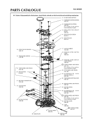
PARTS CATALOGUE Cal. 6A32A ● Order of disassembly for the battery, circuit block, wheels on the front side and switching mechanism 10 SILVER OXIDE BATTERY 11 POWER SWITCH SPRING ...
PARTS CATALOGUE Cal. 6A32A ● Order of disassembly for the battery, circuit block, wheels on the front side and switching mechanism 10 SILVER OXIDE BATTERY 11 POWER SWITCH SPRING ...
Technical Guide
Page 4
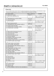
... CLUTCH WHEEL 38 SWITCH CAM 39 MAIN PLATE 0282 452 1 4295 006 1 0100 293 1 TOTAL NUMBER OF PARTS (TO BE ASSEMBLED) 44 4 PARTS CATALOGUE Cal. 6A32A [Parts list] There are determined based on the case design or hand installation height. PARTS NAME 3 DATE DIAL GUARD 4 DATE DIAL (INCOMPLETE) PARTS CODE Number...
... CLUTCH WHEEL 38 SWITCH CAM 39 MAIN PLATE 0282 452 1 4295 006 1 0100 293 1 TOTAL NUMBER OF PARTS (TO BE ASSEMBLED) 44 4 PARTS CATALOGUE Cal. 6A32A [Parts list] There are determined based on the case design or hand installation height. PARTS NAME 3 DATE DIAL GUARD 4 DATE DIAL (INCOMPLETE) PARTS CODE Number...
Technical Guide
Page 5
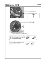
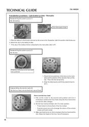
... sure to align them all -purpose movement holder. 5 Foot positions of the dial and main plate to use the all together. TECHNICAL GUIDE DISASSEMBLY 1. Cal. 6A32A Designated area of the dial. Lifting the dial up the dial and remove it. How to damage the calendar frame or the dial with the...
... sure to align them all -purpose movement holder. 5 Foot positions of the dial and main plate to use the all together. TECHNICAL GUIDE DISASSEMBLY 1. Cal. 6A32A Designated area of the dial. Lifting the dial up the dial and remove it. How to damage the calendar frame or the dial with the...
Technical Guide
Page 6
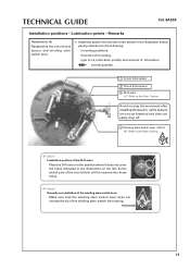
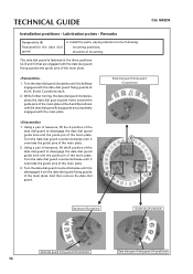
normal quantity 1 Center pipe (AO-3) 2 Lower guide hole of the minute wheel and pinion (AO-3) 3 Guide pin of the train wheel setting lever (AO-3) Main plate (back side) 4 Pin of the setting lever (AO-3) 5 Pin of the setting wheel (AO-3) 6 & 7 Lower holes of oil. TECHNICAL GUIDE Cal. 6A32A Installation positions • Lubrication points • Remarks Reassembly (1) Lubricate the main plate. ❇ Make sure to lubricate the exact lubrication points with an adequate amount of the correct type of the rotor (AO-2) 6
normal quantity 1 Center pipe (AO-3) 2 Lower guide hole of the minute wheel and pinion (AO-3) 3 Guide pin of the train wheel setting lever (AO-3) Main plate (back side) 4 Pin of the setting lever (AO-3) 5 Pin of the setting wheel (AO-3) 6 & 7 Lower holes of oil. TECHNICAL GUIDE Cal. 6A32A Installation positions • Lubrication points • Remarks Reassembly (1) Lubricate the main plate. ❇ Make sure to lubricate the exact lubrication points with an adequate amount of the correct type of the rotor (AO-2) 6
Technical Guide
Page 7
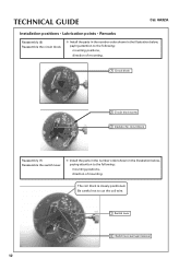
normal quantity liberal quantity 1 Clutch wheel 2 Switch cam 3 Winding stem (AO-3) 4 Yoke (AO-3) 5 Setting lever (AO-3) 6 Winding stem switching lever spring 7 TECHNICAL GUIDE Cal. 6A32A Installation positions • Lubrication points • Remarks Reassembly (2) Lubricate the switching mechanism. ❇ Install the parts in the number order shown in the illustration below, paying attention to the following: mounting positions, direction of mounting, type of oil, lubrication point(s) and amount of lubrication.
normal quantity liberal quantity 1 Clutch wheel 2 Switch cam 3 Winding stem (AO-3) 4 Yoke (AO-3) 5 Setting lever (AO-3) 6 Winding stem switching lever spring 7 TECHNICAL GUIDE Cal. 6A32A Installation positions • Lubrication points • Remarks Reassembly (2) Lubricate the switching mechanism. ❇ Install the parts in the number order shown in the illustration below, paying attention to the following: mounting positions, direction of mounting, type of oil, lubrication point(s) and amount of lubrication.
Technical Guide
Page 8
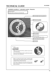
... pinion 9 Battery connection (-) 10 Rotor 11 Rotor 12 Fifth wheel and pinion 13 Intermediate date driving wheel A 14 Third wheel and pinion 8 TECHNICAL GUIDE Cal. 6A32A Installation positions • Lubrication points • Remarks Reassembly (3) Reassemble the wheels and train wheel bridge. ❇ Install the parts in the number order shown in...
... pinion 9 Battery connection (-) 10 Rotor 11 Rotor 12 Fifth wheel and pinion 13 Intermediate date driving wheel A 14 Third wheel and pinion 8 TECHNICAL GUIDE Cal. 6A32A Installation positions • Lubrication points • Remarks Reassembly (3) Reassemble the wheels and train wheel bridge. ❇ Install the parts in the number order shown in...
Technical Guide
Page 9
TECHNICAL GUIDE Cal. 6A32A 15 Train wheel setting lever 16 Fourth wheel and pinion (AO-3) 17 Train wheel bridge Positions of the guide pins for train wheel bridge When handling the plastic parts, use a pair of tweezers to securely hold them, paying attention not to touch the coil board or coil wire. 9 When holding the coil block, be careful not to damage the teeth or pinions.
TECHNICAL GUIDE Cal. 6A32A 15 Train wheel setting lever 16 Fourth wheel and pinion (AO-3) 17 Train wheel bridge Positions of the guide pins for train wheel bridge When handling the plastic parts, use a pair of tweezers to securely hold them, paying attention not to touch the coil board or coil wire. 9 When holding the coil block, be careful not to damage the teeth or pinions.

Technical Guide
Page 10
normal quantity 1 Minute wheel and pinion (AO-3) 2 Pin for crown switch (AO-3) 3 Upper pivot of the rotor (AO-2) 4 Upper pivot of oil. TECHNICAL GUIDE Cal. 6A32A Installation positions • Lubrication points • Remarks Reassembly (4) Lubricate the train wheel bridge. ❇ Make sure to lubricate the exact lubrication points with an adequate amount of the correct type of the rotor (AO-2) 10
normal quantity 1 Minute wheel and pinion (AO-3) 2 Pin for crown switch (AO-3) 3 Upper pivot of the rotor (AO-2) 4 Upper pivot of oil. TECHNICAL GUIDE Cal. 6A32A Installation positions • Lubrication points • Remarks Reassembly (4) Lubricate the train wheel bridge. ❇ Make sure to lubricate the exact lubrication points with an adequate amount of the correct type of the rotor (AO-2) 10
Technical Guide
Page 11
TECHNICAL GUIDE Cal. 6A32A Installation positions • Lubrication points • Remarks Reassembly (5) Reassemble the circuit block spacer and winding stem switch lever. ❇ Install the parts in the number ...
TECHNICAL GUIDE Cal. 6A32A Installation positions • Lubrication points • Remarks Reassembly (5) Reassemble the circuit block spacer and winding stem switch lever. ❇ Install the parts in the number ...
Technical Guide
Page 12
...; Install the parts in the number order shown in the illustration below , paying attention to the following: mounting positions, direction of mounting. TECHNICAL GUIDE Cal. 6A32A Installation positions • Lubrication points • Remarks Reassembly (6) Reassemble the circuit block. ❇ Install the parts in the number order shown in the illustration below...
...; Install the parts in the number order shown in the illustration below , paying attention to the following: mounting positions, direction of mounting. TECHNICAL GUIDE Cal. 6A32A Installation positions • Lubrication points • Remarks Reassembly (6) Reassemble the circuit block. ❇ Install the parts in the number order shown in the illustration below...
Technical Guide
Page 13
TECHNICAL GUIDE Installation positions • Lubrication points • Remarks Reassembly (8) Reassemble the wheels on the back side Cal. 6A32A 1 Intermediate date driving wheel C 2 Date driving wheel Pinion of tweezers to securely hold the plastic parts, paying attention so as shown in the correct direction. ...
TECHNICAL GUIDE Installation positions • Lubrication points • Remarks Reassembly (8) Reassemble the wheels on the back side Cal. 6A32A 1 Intermediate date driving wheel C 2 Date driving wheel Pinion of tweezers to securely hold the plastic parts, paying attention so as shown in the correct direction. ...
Technical Guide
Page 14
... B position of the date dial guard to disengage the date dial guard guide hole and the guide pin of the main plate. 1. TECHNICAL GUIDE Cal. 6A32A Installation positions • Lubrication points • Remarks Reassembly (9) Reassemble the date dial guard. ❇ Install the parts, paying attention to the following: mounting positions, direction...
... B position of the date dial guard to disengage the date dial guard guide hole and the guide pin of the main plate. 1. TECHNICAL GUIDE Cal. 6A32A Installation positions • Lubrication points • Remarks Reassembly (9) Reassemble the date dial guard. ❇ Install the parts, paying attention to the following: mounting positions, direction...
Technical Guide
Page 15
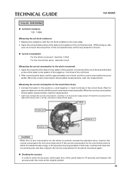
... of the tester to the pattern of the positive (+) terminal of the circuit block and the black probe of the circuit block. TECHNICAL GUIDE Cal. 6A32A VALUE CHECKING ● Coil block resistance 1.28 - 1.48kW [Measuring the coil block resistance] 1. When the currency consumption shows stable measurements, read the measurement. [Measuring the...
... of the tester to the pattern of the positive (+) terminal of the circuit block and the black probe of the circuit block. TECHNICAL GUIDE Cal. 6A32A VALUE CHECKING ● Coil block resistance 1.28 - 1.48kW [Measuring the coil block resistance] 1. When the currency consumption shows stable measurements, read the measurement. [Measuring the...
Technical Guide
Page 16
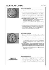
... dial. Reassembling the exterior parts (3) Set the hour hand, minute hand and second hand. Stop the hour hand at the moment the date changes. 2. Cal. 6A32A Clip of the hour hand if necessary. 16 Adjust the height of the battery holder 1. Set the hour hand pointing to the 12 o'clock position...
... dial. Reassembling the exterior parts (3) Set the hour hand, minute hand and second hand. Stop the hour hand at the moment the date changes. 2. Cal. 6A32A Clip of the hour hand if necessary. 16 Adjust the height of the battery holder 1. Set the hour hand pointing to the 12 o'clock position...
Technical Guide
Page 17
... the timing when the date changes. Adjust the position of the height of the minute hand if necessary. Hand installation check ups 1. TECHNICAL GUIDE Cal. 6A32A How to set it again. 3.
... the timing when the date changes. Adjust the position of the height of the minute hand if necessary. Hand installation check ups 1. TECHNICAL GUIDE Cal. 6A32A How to set it again. 3.
Technical Guide
Page 18
...; Keep the positive terminal in this point onward. 2. Rotating the crown counterclockwise will return to the normal mode within 2 to the 12 o'clock position. Cal. 6A32A Notes and tips When fixing in the inner frame, take care so as this may cause an IC malfunction. * In a case that an IC malfunction...
...; Keep the positive terminal in this point onward. 2. Rotating the crown counterclockwise will return to the normal mode within 2 to the 12 o'clock position. Cal. 6A32A Notes and tips When fixing in the inner frame, take care so as this may cause an IC malfunction. * In a case that an IC malfunction...
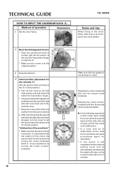
Technical Guide
Page 19
... and forth, and then stop it. 4. After confirming that the date dial has been stopped, turn the crown counterclockwise to 3 minutes. 19 TECHNICAL GUIDE Cal. 6A32A HOW TO INPUT THE CALENDAR DATA (2) Method of operation 5 Initial position adjustment for the calendar (2) (Set the date dial to align the numeral "1" in the...
... and forth, and then stop it. 4. After confirming that the date dial has been stopped, turn the crown counterclockwise to 3 minutes. 19 TECHNICAL GUIDE Cal. 6A32A HOW TO INPUT THE CALENDAR DATA (2) Method of operation 5 Initial position adjustment for the calendar (2) (Set the date dial to align the numeral "1" in the...
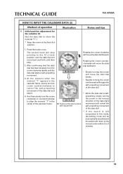
Technical Guide
Page 20
... movement. 3. Rotating the crown counterclockwise will move the date dial backward. • Slowly turning the crown will move the date dial forward. TECHNICAL GUIDE Cal. 6A32A HOW TO INPUT THE CALENDAR DATA (3) Method of operation Illustration Notes and tips 6 Set the date. * Keep the crown at the first click position. 1. Press...
... movement. 3. Rotating the crown counterclockwise will move the date dial backward. • Slowly turning the crown will move the date dial forward. TECHNICAL GUIDE Cal. 6A32A HOW TO INPUT THE CALENDAR DATA (3) Method of operation Illustration Notes and tips 6 Set the date. * Keep the crown at the first click position. 1. Press...