
Constellation.2 SATA Product Manual
Page 10
... information about how Serial ATA emulates parallel ATA, refer to provide backward compatibility with Serial ATA devices like Device 0 devices. It is not necessary to set any jumpers or other configuration options. • Thinner and more flexible cabling for improved enclosure airflow and ease of installation. • Scalability to as a Device 0 (master...
... information about how Serial ATA emulates parallel ATA, refer to provide backward compatibility with Serial ATA devices like Device 0 devices. It is not necessary to set any jumpers or other configuration options. • Thinner and more flexible cabling for improved enclosure airflow and ease of installation. • Scalability to as a Device 0 (master...
Constellation.2 SATA Product Manual
Page 31
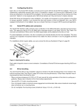
... in-lb, ± 0.45 in Figure 5, page 25. There is no master/slave relationship because each drive is considered a master in any jumpers on two separate ports. Constellation.2 Serial ATA drives support latching SATA connectors. 4.4 Drive mounting You can mount the drive in a point-to the... three ground connections. Please refer to Section 4.5 for connector pin definitions. Attaching SATA cabling Each cable is usually not necessary to set any orientation using four screws in the side-mounting holes or four screws in (0.76 mm) around the entire perimeter of the ...
... in-lb, ± 0.45 in Figure 5, page 25. There is no master/slave relationship because each drive is considered a master in any jumpers on two separate ports. Constellation.2 Serial ATA drives support latching SATA connectors. 4.4 Drive mounting You can mount the drive in a point-to the... three ground connections. Please refer to Section 4.5 for connector pin definitions. Attaching SATA cabling Each cable is usually not necessary to set any orientation using four screws in the side-mounting holes or four screws in (0.76 mm) around the entire perimeter of the ...
Constellation SAS Product Manual
Page 55
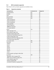
... supported IMMED bit supported VS (vendor specific) Inquiry Date Code page (C1h) Device Behavior page (C3h) Firmware Numbers page (C0h) Implemented Operating Def page (81h) Jumper Settings page (C2h) Supported Vital Product Data page (00h) Unit Serial Number page (80h) Lock-unlock cache Log Select PCR bit DU bit DS bit TSD...
... supported IMMED bit supported VS (vendor specific) Inquiry Date Code page (C1h) Device Behavior page (C3h) Firmware Numbers page (C0h) Implemented Operating Def page (81h) Jumper Settings page (C2h) Supported Vital Product Data page (00h) Unit Serial Number page (80h) Lock-unlock cache Log Select PCR bit DU bit DS bit TSD...

Constellation SATA Product Manual
Page 10
...software as a Device 0 (master) and Device 1 (slave) accessed at the same set of installation. • Scalability to set of registers that emulates a master/slave environment manages two sets of your current system and expect all emulated. For additional information about how Serial ATA ..., PIO and DMA data transfers, resets, and interrupts are Device 0 (master) devices. The Serial ATA host adapter contains a set any jumpers or other configuration options. • Thinner and more flexible cabling for improved enclosure airflow and ease of host bus addresses. Serial ATA...
...software as a Device 0 (master) and Device 1 (slave) accessed at the same set of installation. • Scalability to set of registers that emulates a master/slave environment manages two sets of your current system and expect all emulated. For additional information about how Serial ATA ..., PIO and DMA data transfers, resets, and interrupts are Device 0 (master) devices. The Serial ATA host adapter contains a set any jumpers or other configuration options. • Thinner and more flexible cabling for improved enclosure airflow and ease of host bus addresses. Serial ATA...
Constellation SATA Product Manual
Page 27
... cover them with the Serial ATA host adapter. however, if you have a motherboard or host adapter that does not support autonegotiation: • Install a jumper as if they were both "masters" on the Serial ATA interface connects point-to -point relationship. If you connect the drive and receive a "drive... it in Figure 3, page 22 below to limit the data transfer rate to 1.5 Gbits per second (and leave the drive connected to set any jumpers on a grounded wrist strap, or ground yourself frequently by its edges or frame only. • The drive is plugged into a grounded outlet.
... cover them with the Serial ATA host adapter. however, if you have a motherboard or host adapter that does not support autonegotiation: • Install a jumper as if they were both "masters" on the Serial ATA interface connects point-to -point relationship. If you connect the drive and receive a "drive... it in Figure 3, page 22 below to limit the data transfer rate to 1.5 Gbits per second (and leave the drive connected to set any jumpers on a grounded wrist strap, or ground yourself frequently by its edges or frame only. • The drive is plugged into a grounded outlet.
Constellation SATA Product Manual
Page 28
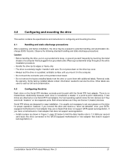
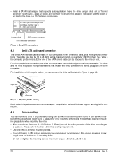
... the mounting screws (maximum torque: 4.5 inch-lb, ± 0.45 in Figure 4, page 22. • Install a SATA host adapter that supports autonegotiation, leave the drive jumper block set to "Normal operation" (see Figure 3, page 22 below), and connect the drive to that enable the direct connection to be hot pluggable and blind mateable.... For direct backplane connection, the drive connectors are inserted directly into the host receptacle. Attaching SATA cabling Each cable is keyed to 1.5 Gbits per second Jumper block SATA power connector SATA interface connector Figure 3.
... the mounting screws (maximum torque: 4.5 inch-lb, ± 0.45 in Figure 4, page 22. • Install a SATA host adapter that supports autonegotiation, leave the drive jumper block set to "Normal operation" (see Figure 3, page 22 below), and connect the drive to that enable the direct connection to be hot pluggable and blind mateable.... For direct backplane connection, the drive connectors are inserted directly into the host receptacle. Attaching SATA cabling Each cable is keyed to 1.5 Gbits per second Jumper block SATA power connector SATA interface connector Figure 3.

