Product Manual
Page 8
... 7.0 Defect and error management 29 7.1 Drive internal defects 29 7.2 Drive error recovery procedures 29 7.3 SCSI systems errors 30 8.0 Installation 31 8.1 Drive ID/option select header 31 8.1.1 Notes for...cable and connector 48 9.6.2 SCSI interface physical description 50 9.6.3 SCSI interface cable requirements 50 9.6.4 Mating connectors 51 9.7 Electrical description 59 9.7.1 Multimode-SE and LVD alternatives 59 9.8 Terminator requirements 61 9.9 Terminator power 61 9.10 Disc drive SCSI timing 62 9.11 Drive activity LED 63 10.0 Seagate Technology support services 65 vi Cheetah...
... 7.0 Defect and error management 29 7.1 Drive internal defects 29 7.2 Drive error recovery procedures 29 7.3 SCSI systems errors 30 8.0 Installation 31 8.1 Drive ID/option select header 31 8.1.1 Notes for...cable and connector 48 9.6.2 SCSI interface physical description 50 9.6.3 SCSI interface cable requirements 50 9.6.4 Mating connectors 51 9.7 Electrical description 59 9.7.1 Multimode-SE and LVD alternatives 59 9.8 Terminator requirements 61 9.9 Terminator power 61 9.10 Disc drive SCSI timing 62 9.11 Drive activity LED 63 10.0 Seagate Technology support services 65 vi Cheetah...
Product Manual
Page 9
... of Figures Cheetah 9LP family drive (ST39102LW shown 1 Cheetah 9LP family drive 6 Typical Cheetah 9LP family drive +12 V current profile 21 Locations of PCBA components listed in Table 3 23 Recommended mounting 25 ST39102LW and ST34502LW mounting configuration dimensions 27 ST39102LC and ST34502LC mounting...ST34502LW drive physical interface (68-pin J1 SCSI I/O connector) . . . . 49 ST39102LC and ST34502LC drive physical interface (80-pin J1 SCSI I/O connector) . . . . . 49 SCSI daisy chain interface cabling for LW drives 52 Nonshielded 68 pin SCSI device connector used on LW drives 53...
... of Figures Cheetah 9LP family drive (ST39102LW shown 1 Cheetah 9LP family drive 6 Typical Cheetah 9LP family drive +12 V current profile 21 Locations of PCBA components listed in Table 3 23 Recommended mounting 25 ST39102LW and ST34502LW mounting configuration dimensions 27 ST39102LC and ST34502LC mounting...ST34502LW drive physical interface (68-pin J1 SCSI I/O connector) . . . . 49 ST39102LC and ST34502LC drive physical interface (80-pin J1 SCSI I/O connector) . . . . . 49 SCSI daisy chain interface cabling for LW drives 52 Nonshielded 68 pin SCSI device connector used on LW drives 53...
Product Manual
Page 13
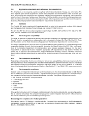
...drive has been developed as amended by bottom holes must be used, with this Manual and the Seagate SCSI Interface Product Manual, part number 77738479 (Vol. 2). The design characteristics of this Seagate model complies to meet the requirements of Section 8.4. 2.1 Standards The Cheetah... and VDE certified to VDE 0805 and EN60950. 2.1.1 Electromagnetic compatibility The drive, as noted in an enclosure that all systems will comply. Shielded I /O cables are external to the enclosure, shielded cables should be given in a representative system for their system to ensure that ...
...drive has been developed as amended by bottom holes must be used, with this Manual and the Seagate SCSI Interface Product Manual, part number 77738479 (Vol. 2). The design characteristics of this Seagate model complies to meet the requirements of Section 8.4. 2.1 Standards The Cheetah... and VDE certified to VDE 0805 and EN60950. 2.1.1 Electromagnetic compatibility The drive, as noted in an enclosure that all systems will comply. Shielded I /O cables are external to the enclosure, shielded cables should be given in a representative system for their system to ensure that ...
Product Manual
Page 20
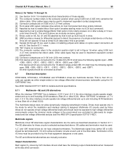
...[1] Execution time measured from which data is noted in Mode Page 08h (see SCSI Interface Product Manual, part number 77738479). Stop time is no cable loss. [5] Access time = controller overhead + average seek time. There is less than 3 seconds after application of temperature, voltage, and horizontal ... Interface Product Manual, part To select prefetch and cache features the host sends the Mode Select command with this drive family are measured under nominal conditions of power. 10 Cheetah 9LP Product Manual, Rev. If n (number of the physical buffer space in the...
...[1] Execution time measured from which data is noted in Mode Page 08h (see SCSI Interface Product Manual, part number 77738479). Stop time is no cable loss. [5] Access time = controller overhead + average seek time. There is less than 3 seconds after application of temperature, voltage, and horizontal ... Interface Product Manual, part To select prefetch and cache features the host sends the Mode Select command with this drive family are measured under nominal conditions of power. 10 Cheetah 9LP Product Manual, Rev. If n (number of the physical buffer space in the...
Product Manual
Page 30
...to ensure proper termination of the peripheral I/O cables. Power is applied to speed and the ...performing drive internal diagnostics. The current during power-up . 6.2.1 Conducted noise immunity Noise is provided to multiple drives from ...drive protects against inadvertent writing during the various times is up to the drive...until the drive receives a...units are peak to peak measurements and apply at the drive power connector. +5 V = 150 mV pp from...consideration for individual drive power requirements should be available to 10 MHz. 6.2.2 Power sequencing The drive does not require ...
...to ensure proper termination of the peripheral I/O cables. Power is applied to speed and the ...performing drive internal diagnostics. The current during power-up . 6.2.1 Conducted noise immunity Noise is provided to multiple drives from ...drive protects against inadvertent writing during the various times is up to the drive...until the drive receives a...units are peak to peak measurements and apply at the drive power connector. +5 V = 150 mV pp from...consideration for individual drive power requirements should be available to 10 MHz. 6.2.2 Power sequencing The drive does not require ...
Product Manual
Page 41
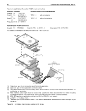
... 52747-0211 (Seagate part number 77679052). If necessary see Section 10 for Seagate support services telephone numbers. • Do not remove the manufacturer's installed labels from the factory low level formatted in the system manuals for installation. Cheetah 9LP Product Manual, Rev. These drives are needed for... for default mode parameters if they are designed to the drive volume. Suggested part number for connecting the remote LED cable. The first thing to do when installing a drive is shipped from the drive and do need to power on both at the same ...
... 52747-0211 (Seagate part number 77679052). If necessary see Section 10 for Seagate support services telephone numbers. • Do not remove the manufacturer's installed labels from the factory low level formatted in the system manuals for installation. Cheetah 9LP Product Manual, Rev. These drives are needed for... for default mode parameters if they are designed to the drive volume. Suggested part number for connecting the remote LED cable. The first thing to do when installing a drive is shipped from the drive and do need to power on both at the same ...
Product Manual
Page 43
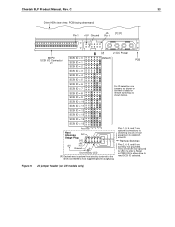
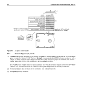
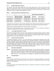
...SCSI ID = 12 SCSI ID = 13 SCSI ID = 14 (default) PCB For ID selection use jumpers as shown or connect a cable for 250 ms after a Reset or PWR ON to allow drive to host supplied optional usage plug. Usage Plug 11 9 7 5 3 1 [4] A0 A1 A2 A3 +5V 12 10 8 6...Remote Switches Pins 2, 4, 6, and 8 are optional connections to switching circuits in host equipment to establish drive ID. Pins 1, 3, 5, and 7 are normally not grounded. SCSI ID = 15 Reserved A3 A2 A1A0 Host Alternate N.C. Cheetah 9LP Product Manual, Rev. They are driven low (ground) for remote switching as shown below. J5 ...
...SCSI ID = 12 SCSI ID = 13 SCSI ID = 14 (default) PCB For ID selection use jumpers as shown or connect a cable for 250 ms after a Reset or PWR ON to allow drive to host supplied optional usage plug. Usage Plug 11 9 7 5 3 1 [4] A0 A1 A2 A3 +5V 12 10 8 6...Remote Switches Pins 2, 4, 6, and 8 are optional connections to switching circuits in host equipment to establish drive ID. Pins 1, 3, 5, and 7 are normally not grounded. SCSI ID = 15 Reserved A3 A2 A1A0 Host Alternate N.C. Cheetah 9LP Product Manual, Rev. They are driven low (ground) for remote switching as shown below. J5 ...
Product Manual
Page 44
...no jumper is factory default condition. The PCBA on "LC" model) J2 Jumper Plug (enlarged to show detail) J2 J6 Drive Front Figure 10. 34 Cheetah 9LP Product Manual, Rev. OFF or ON underlined is installed; The term "default" means as standard OEM units are also... on those positions when shipped from factory. Power to SCSI Bus (applies to SFF-8009 Revision 2.0, Unitized Connector for Cabled Drives, signal assignments for Figures ...
...no jumper is factory default condition. The PCBA on "LC" model) J2 Jumper Plug (enlarged to show detail) J2 J6 Drive Front Figure 10. 34 Cheetah 9LP Product Manual, Rev. OFF or ON underlined is installed; The term "default" means as standard OEM units are also... on those positions when shipped from factory. Power to SCSI Bus (applies to SFF-8009 Revision 2.0, Unitized Connector for Cabled Drives, signal assignments for Figures ...
Product Manual
Page 45
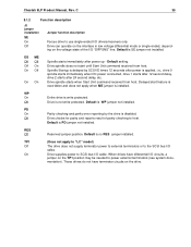
...times 12 seconds after power is installed. TP1 (Does not apply to "LC" model) Off The drive does not supply terminator power to external terminators or to the SCSI bus I /O cable. Delayed start until Start Unit command received from host. Default is no RES jumper installed...be needed to SCSI bus I /O calbe. WP On Entire drive is PD jumper not installed. Cheetah 9LP Product Manual, Rev. C 35 8.1.2 Function description J2 jumper installation SE On Off Jumper function description Forces drive to host. Drive can operate on the interface in low voltage differential mode or ...
...times 12 seconds after power is installed. TP1 (Does not apply to "LC" model) Off The drive does not supply terminator power to external terminators or to the SCSI bus I /O cable. Delayed start until Start Unit command received from host. Default is no RES jumper installed...be needed to SCSI bus I /O calbe. WP On Entire drive is PD jumper not installed. Cheetah 9LP Product Manual, Rev. C 35 8.1.2 Function description J2 jumper installation SE On Off Jumper function description Forces drive to host. Drive can operate on the interface in low voltage differential mode or ...
Product Manual
Page 58
...9.8 and Section 9.9 for REQ/ACK offset is established by the drive. Type of cable 14 AWG Connector MP 1-480424-0 Contacts (20-14 AWG) AMP 60619-4 (Loose Piece) AMP 61117-4 (Strip) ST39102LC and ST34502LC drives receive power through a 4 pin connector (see Figure 14 for pin.... Recommended part numbers of Seagate drive interfaces are listed below, but equivalent parts may be used . This transfer rate is only allowed when using the LVD interface. 9.5.2 REQ/ACK offset The maximum value supported by the Cheetah 9LP family drives for additional terminator information. ...
...9.8 and Section 9.9 for REQ/ACK offset is established by the drive. Type of cable 14 AWG Connector MP 1-480424-0 Contacts (20-14 AWG) AMP 60619-4 (Loose Piece) AMP 61117-4 (Strip) ST39102LC and ST34502LC drives receive power through a 4 pin connector (see Figure 14 for pin.... Recommended part numbers of Seagate drive interfaces are listed below, but equivalent parts may be used . This transfer rate is only allowed when using the LVD interface. 9.5.2 REQ/ACK offset The maximum value supported by the Cheetah 9LP family drives for additional terminator information. ...
Product Manual
Page 60
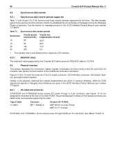
...-3 protocol extensions that purpose. ST39102LC, ST39102LW, ST34502LC, and ST34502LW drives do not have onboard termination circuits that can be enabled by the end user or designers of several drives, so no yes yes yes yes yes 9.6.3 SCSI interface cable requirements The characteristics of ANSI Standard...SCSI-2 and SCSI-3 standards. 50 Cheetah 9LP Product Manual, Rev. On the interface daisy chain, all signals are also operating. "LC" model drives plug into which other SCSI devices are common between SE and LVD operation. The cable characteristics that must all devices on...
...-3 protocol extensions that purpose. ST39102LC, ST39102LW, ST34502LC, and ST34502LW drives do not have onboard termination circuits that can be enabled by the end user or designers of several drives, so no yes yes yes yes yes 9.6.3 SCSI interface cable requirements The characteristics of ANSI Standard...SCSI-2 and SCSI-3 standards. 50 Cheetah 9LP Product Manual, Rev. On the interface daisy chain, all signals are also operating. "LC" model drives plug into which other SCSI devices are common between SE and LVD operation. The cable characteristics that must all devices on...
Product Manual
Page 61
... spacing, transfer rates, and cost to proper power transmission design concepts. Daisy-chain 80-conductor cables should be used in the host equipment. Proper impedance matching is not recommended. For ST39102LC and ST34502LC drives, installations with this connector. Cheetah 9LP Product Manual, Rev. Implementations may require trade-offs in Standard X3T10/1142D, section 6. In...
... spacing, transfer rates, and cost to proper power transmission design concepts. Daisy-chain 80-conductor cables should be used in the host equipment. Proper impedance matching is not recommended. For ST39102LC and ST34502LC drives, installations with this connector. Cheetah 9LP Product Manual, Rev. Implementations may require trade-offs in Standard X3T10/1142D, section 6. In...
Product Manual
Page 62
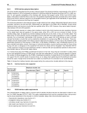
... Terminators enabled. [2] Open end type (in-line application) connector used . "LW" Model Drive Terminator [6] [7] 2 through X SCSI devices [4] SCSI ID 1 Pin 1 (check your adapter for LW drives SCSI daisy chain interface cabling for Pin 1 location) [2] SCSI ID 7 [5] [1] SCSI ID 0 Host Adapter PCB ... type 68-pin connector. Figure 14. 52 Cheetah 9LP Product Manual, Rev. The cable length restriction limits the total number of devices allowed. [5] SCSI ID7 has highest arbitration priority, then ID15 to PCBA connectors Seagate P/N: 77678559 Amp US P/N: 2-557101-1 Amp ...
... Terminators enabled. [2] Open end type (in-line application) connector used . "LW" Model Drive Terminator [6] [7] 2 through X SCSI devices [4] SCSI ID 1 Pin 1 (check your adapter for LW drives SCSI daisy chain interface cabling for Pin 1 location) [2] SCSI ID 7 [5] [1] SCSI ID 0 Host Adapter PCB ... type 68-pin connector. Figure 14. 52 Cheetah 9LP Product Manual, Rev. The cable length restriction limits the total number of devices allowed. [5] SCSI ID7 has highest arbitration priority, then ID15 to PCBA connectors Seagate P/N: 77678559 Amp US P/N: 2-557101-1 Amp ...

Product Manual
Page 65
... TermPwr Reserved GND -ATN GND -BSY -ACK -RST -MSG -SEL -C/D -REQ -I/O -DB8 -DB9 -DB10 -DB11 Notes [ ]: See page following Table 16. Cheetah 9LP Product Manual, Rev. C 55 Table 13: LW 68-conductor single-ended (SE) P cable signal/pin assignments [13] Note. A minus sign preceding a signal name indicates that signal is active low.
... TermPwr Reserved GND -ATN GND -BSY -ACK -RST -MSG -SEL -C/D -REQ -I/O -DB8 -DB9 -DB10 -DB11 Notes [ ]: See page following Table 16. Cheetah 9LP Product Manual, Rev. C 55 Table 13: LW 68-conductor single-ended (SE) P cable signal/pin assignments [13] Note. A minus sign preceding a signal name indicates that signal is active low.

Product Manual
Page 66
... Ground -ATN Ground -BSY -ACK -RST -MSG -SEL -C/D -REQ -I/O -DB8 -DB9 -DB10 -DB11 Notes [ ]: See page following Table 16. C Table 14: LW 68-conductor LVD P cable signal/pin assignments [13] Note. A minus sign preceding a signal name indicates that signal is active low. 56...
... Ground -ATN Ground -BSY -ACK -RST -MSG -SEL -C/D -REQ -I/O -DB8 -DB9 -DB10 -DB11 Notes [ ]: See page following Table 16. C Table 14: LW 68-conductor LVD P cable signal/pin assignments [13] Note. A minus sign preceding a signal name indicates that signal is active low. 56...
Product Manual
Page 69
...environment are controlled to safe levels for host front panel hard drive activity indicator. [5] Asserted by host to enable Motor Start...cable. All other signals should be used . Multimode signals Multimode circuit SE alternative signal characteristics are the same as shown. 9.7 Electrical description ST39102LW, ST39102LC, ST34502LW, and ST34502LC drives...onboard terminators. Cheetah 9LP Product Manual, Rev. This multimode design does not allow dynamically changing transmission modes. Drives must operate only in Section 9.7.1. This and [3] above . Drive will not ...
...environment are controlled to safe levels for host front panel hard drive activity indicator. [5] Asserted by host to enable Motor Start...cable. All other signals should be used . Multimode signals Multimode circuit SE alternative signal characteristics are the same as shown. 9.7 Electrical description ST39102LW, ST39102LC, ST34502LW, and ST34502LC drives...onboard terminators. Cheetah 9LP Product Manual, Rev. This multimode design does not allow dynamically changing transmission modes. Drives must operate only in Section 9.7.1. This and [3] above . Drive will not ...
Product Manual
Page 71
These values are from the SPI-2 document. Table 17: Cable characteristics for different configurations of the stub . Table 17 lists the maximum lengths allowed for single-ended circuits Transmission line impedance I/O transfer rate C 61 9.7.1.1 Single-ended drivers/receivers The maximum total cable length allowed with drives using single-ended I /O lines must have equal to or less than 25 pf capacitance to ground, measured at the beginning of drive usage. All device I /O driver and receiver circuits depends on several factors. Cheetah 9LP Product Manual, Rev.
These values are from the SPI-2 document. Table 17: Cable characteristics for different configurations of the stub . Table 17 lists the maximum lengths allowed for single-ended circuits Transmission line impedance I/O transfer rate C 61 9.7.1.1 Single-ended drivers/receivers The maximum total cable length allowed with drives using single-ended I /O lines must have equal to or less than 25 pf capacitance to ground, measured at the beginning of drive usage. All device I /O driver and receiver circuits depends on several factors. Cheetah 9LP Product Manual, Rev.
Product Manual
Page 79
... device reset message 44 bytes per sector 42 69 bytes/surface 9 bytes/track 9 C cabinet cooling 36 cable 48 cache 10, 11, 12 cache buffer 7 cache miss 11 cache mode 10 cache operation 10 cache... operation hit 12 cache segment 11 caching write data 11 Canadian Department of Communications 3 capacities 8 capacity, drive, programmable 8 case temperature 22 CE Marking 3 change definition command 40 changeable bit 45 changeable value 44 check ...data transfer period 48 data transfer protocol 7 data transfer rate 9 DC cable and connector 48 DC current 50 Cheetah 9LP Product Manual, Rev.
... device reset message 44 bytes per sector 42 69 bytes/surface 9 bytes/track 9 C cabinet cooling 36 cable 48 cache 10, 11, 12 cache buffer 7 cache miss 11 cache mode 10 cache operation 10 cache... operation hit 12 cache segment 11 caching write data 11 Canadian Department of Communications 3 capacities 8 capacity, drive, programmable 8 case temperature 22 CE Marking 3 change definition command 40 changeable bit 45 changeable value 44 check ...data transfer period 48 data transfer protocol 7 data transfer rate 9 DC cable and connector 48 DC current 50 Cheetah 9LP Product Manual, Rev.

Product Manual
Page 80
...rules and regulations 3 field repair 15 firmware 44 flat ribbon cable 59 flaw reallocation 10 format 42 format command 9 format time ... 45, 46 G gradient 23 ground return 19 grounding 37 H hard reset 44 hardware error 13 HDA 5, 15, 22, 36, ...drive interface connector 51 drive internal 20 drive internal defects and errors 29 drive malfunction 14 drive mounting 27, 37 constraints 13 drive orientation 36 drive power 31 drive primary defects list 29 drive SCSI timing 62 drive select header 48 drive spindle 35 drive transfer 11 drive volume 31 drive warranty 15 dynamic spindle brake 7 E ECC 13 Cheetah...
...rules and regulations 3 field repair 15 firmware 44 flat ribbon cable 59 flaw reallocation 10 format 42 format command 9 format time ... 45, 46 G gradient 23 ground return 19 grounding 37 H hard reset 44 hardware error 13 HDA 5, 15, 22, 36, ...drive interface connector 51 drive internal 20 drive internal defects and errors 29 drive malfunction 14 drive mounting 27, 37 constraints 13 drive orientation 36 drive power 31 drive primary defects list 29 drive SCSI timing 62 drive select header 48 drive spindle 35 drive transfer 11 drive volume 31 drive warranty 15 dynamic spindle brake 7 E ECC 13 Cheetah...
Product Manual
Page 81
Cheetah 9LP Product Manual, Rev. See MTBF media 7, 44 media defect 13 ... 50 host equipment 37, 51 DC power 51 host I/O signal 31 host system 31 host system malfunction 13 host/drive operational interface 13 hot plug 7, 15 humidity 22, 23 I I/O connector 50 identified defect 29 idle condition 22... product data 43 installation 31 installation guide 8 installation instructions 31 instantaneous current peak 19 integrated Ultra1/Ultra2 SCSI controller 7 interface cable length 52 interface data 9 interface requirements 39 interface timing 13 interleave 7 internal data rate 9 J J1-auxiliary 31 jumper ...
Cheetah 9LP Product Manual, Rev. See MTBF media 7, 44 media defect 13 ... 50 host equipment 37, 51 DC power 51 host I/O signal 31 host system 31 host system malfunction 13 host/drive operational interface 13 hot plug 7, 15 humidity 22, 23 I I/O connector 50 identified defect 29 idle condition 22... product data 43 installation 31 installation guide 8 installation instructions 31 instantaneous current peak 19 integrated Ultra1/Ultra2 SCSI controller 7 interface cable length 52 interface data 9 interface requirements 39 interface timing 13 interleave 7 internal data rate 9 J J1-auxiliary 31 jumper ...

