Product Manual
Page 7
F v Contents 1.0 Introduction 1 2.0 Drive specifications 3 2.1 Specification summary table 3 2.2 Formatted capacity 5 2.2.1 LBA mode 5 2.3 Default... 13 2.14.2 Electromagnetic compatibility 13 2.14.3 FCC verification 13 3.0 Configuring and mounting the drive 15 3.1 Handling and static discharge precautions 15 3.2 Breather filter hole precautions 16 3.3 Jumper ... 17 3.3.2 Cable-select option 17 3.3.3 Alternate capacity jumper 17 3.3.4 Ultra ATA/100 cable 18 3.4 Drive mounting 18 4.0 ATA interface 21 4.1 ATA interface signals and connector pins 21 4.1.1 Supported ATA commands...
F v Contents 1.0 Introduction 1 2.0 Drive specifications 3 2.1 Specification summary table 3 2.2 Formatted capacity 5 2.2.1 LBA mode 5 2.3 Default... 13 2.14.2 Electromagnetic compatibility 13 2.14.3 FCC verification 13 3.0 Configuring and mounting the drive 15 3.1 Handling and static discharge precautions 15 3.2 Breather filter hole precautions 16 3.3 Jumper ... 17 3.3.2 Cable-select option 17 3.3.3 Alternate capacity jumper 17 3.3.4 Ultra ATA/100 cable 18 3.4 Drive mounting 18 4.0 ATA interface 21 4.1 ATA interface signals and connector pins 21 4.1.1 Supported ATA commands...

Product Manual
Page 9
Figure 4. Typical 5V startup and operation current profile 8 Typical 12V startup and operation current profile 8 Breather filter hole location 16 Master/slave jumper settings 17 Ultra ATA cable connectors 18 Mounting dimensions-top, side and end view 19 I/O pins and supported ATA signals 22 U Series 9 ce Product Manual, Rev. Figure 6. F vii Figure 7. Figure 3. Figure 5. List of Figures Figure 1. Figure 2.
Figure 4. Typical 5V startup and operation current profile 8 Typical 12V startup and operation current profile 8 Breather filter hole location 16 Master/slave jumper settings 17 Ultra ATA cable connectors 18 Mounting dimensions-top, side and end view 19 I/O pins and supported ATA signals 22 U Series 9 ce Product Manual, Rev. Figure 6. F vii Figure 7. Figure 3. Figure 5. List of Figures Figure 1. Figure 2.
Product Manual
Page 11
1.0 Introduction This manual describes the functional, mechanical and interface specifications for the following Seagate® U Series 9® ce model drives: • ST3160022ACE • ST3120025ACE • ST380012ACE These drives provide the following key features: • High instantaneous (burst) data transfer rates (up to 100 Mbytes per second) using Ultra DMA mode 5. • Giant magnetoresistive (...
1.0 Introduction This manual describes the functional, mechanical and interface specifications for the following Seagate® U Series 9® ce model drives: • ST3160022ACE • ST3120025ACE • ST380012ACE These drives provide the following key features: • High instantaneous (burst) data transfer rates (up to 100 Mbytes per second) using Ultra DMA mode 5. • Giant magnetoresistive (...
Product Manual
Page 13
... (sec typical) Startup current (typical) 12V (peak) Track-to indicate ST3160022ACE, ST3120025ACE, and ST380012ACE model drives. 2.1 Specification summary table The specifications listed in this manual. Drive specification Formatted Gbytes (512 bytes/sector) Guaranteed sectors Bytes per sector Default sectors per track Default ...section of this table are measured under ambient conditions, at 25°C, and nominal power. For convenience, the phrases the drive and this drive are used throughout this manual to -track seek time (msec typical) Average seek, read (msec typical) Average seek, ...
... (sec typical) Startup current (typical) 12V (peak) Track-to indicate ST3160022ACE, ST3120025ACE, and ST380012ACE model drives. 2.1 Specification summary table The specifications listed in this manual. Drive specification Formatted Gbytes (512 bytes/sector) Guaranteed sectors Bytes per sector Default sectors per track Default ...section of this table are measured under ambient conditions, at 25°C, and nominal power. For convenience, the phrases the drive and this drive are used throughout this manual to -track seek time (msec typical) Average seek, read (msec typical) Average seek, ...

Product Manual
Page 14
Drive specification Read/write power (typical) Idle mode (typical) Standby mode (typical) Sleep mode (typical) Voltage tolerance (including noise) Ambient temperature Temperature gradient (°C per hour ...) Altitude, operating Altitude, nonoperating (below mean sea level, max) Shock, operating (Gs max at 2 msec) Shock, nonoperating (Gs max at 2 msec) Vibration, operating Vibration, nonoperating Drive acoustics Sound power (bels) Idle* Quiet seek Nonrecoverable read errors Mean time between failures (power-on hours) Service life Contact start-stop cycles (25°...
Drive specification Read/write power (typical) Idle mode (typical) Standby mode (typical) Sleep mode (typical) Voltage tolerance (including noise) Ambient temperature Temperature gradient (°C per hour ...) Altitude, operating Altitude, nonoperating (below mean sea level, max) Shock, operating (Gs max at 2 msec) Shock, nonoperating (Gs max at 2 msec) Vibration, operating Vibration, nonoperating Drive acoustics Sound power (bels) Idle* Quiet seek Nonrecoverable read errors Mean time between failures (power-on hours) Service life Contact start-stop cycles (25°...
Product Manual
Page 15
...80 Gbytes Guaranteed sectors 312,581,808 234,441,648 156,301,488 Bytes per track 63 2.4 Physical organization Model ST3160022ACE ST3120025ACE ST380012ACE Read/write heads 4 3 2 Number of guaranteed sectors as defined above. F 5 See Section 4.1.2, "Identify Device command" (words 60-61 and 100-103) for additional information about 48bit addressing support of drives.../write heads 16 Sectors per sector 512 512 512 2.2.1 LBA mode When addressing these drives in LBA mode, all blocks (sectors) are consecutively numbered from 0 to n-1, where... kbytes) U Series 9 ce Product Manual, Rev.
...80 Gbytes Guaranteed sectors 312,581,808 234,441,648 156,301,488 Bytes per track 63 2.4 Physical organization Model ST3160022ACE ST3120025ACE ST380012ACE Read/write heads 4 3 2 Number of guaranteed sectors as defined above. F 5 See Section 4.1.2, "Identify Device command" (words 60-61 and 100-103) for additional information about 48bit addressing support of drives.../write heads 16 Sectors per sector 512 512 512 2.2.1 LBA mode When addressing these drives in LBA mode, all blocks (sectors) are consecutively numbered from 0 to n-1, where... kbytes) U Series 9 ce Product Manual, Rev.

Product Manual
Page 16
... single-track seeks in the table below are defined as follows: • Track-to -track Average Average latency: Read All times are measured using drive diagnostics. 2.6 Physical characteristics Drive specification Maximum height (mm) (inches) Maximum width (mm) (inches) Maximum length Typical weight (mm) (inches) (grams) (pounds) 26.035 1.028 101.6 4.00 146...
... single-track seeks in the table below are defined as follows: • Track-to -track Average Average latency: Read All times are measured using drive diagnostics. 2.6 Physical characteristics Drive specification Maximum height (mm) (inches) Maximum width (mm) (inches) Maximum length Typical weight (mm) (inches) (grams) (pounds) 26.035 1.028 101.6 4.00 146...

Product Manual
Page 17
...10.3 0.900 0.900 0.584 0.393 0.144 0.144 0.570 0.687 0.015 0.015 *During periods of power-on to the time that the drive spindle reaches operating speed. • Seek mode During seek mode, the read/write actuator arm moves toward a specific position on a 16-sector write ... Idle Average (watts, 25° C) - 6.7 5V typ amps - 0.410 12V typ amps 2.6 (peak) 0.380 Operating 40% r/w, 40% seek, 20% inop. U Series 9 ce Product Manual, Rev. Seek mode power represents the worstcase power consumption, using 5.0V and 12.0V input voltage at 25°C ambient temperature. • Spinup...
...10.3 0.900 0.900 0.584 0.393 0.144 0.144 0.570 0.687 0.015 0.015 *During periods of power-on to the time that the drive spindle reaches operating speed. • Seek mode During seek mode, the read/write actuator arm moves toward a specific position on a 16-sector write ... Idle Average (watts, 25° C) - 6.7 5V typ amps - 0.410 12V typ amps 2.6 (peak) 0.380 Operating 40% r/w, 40% seek, 20% inop. U Series 9 ce Product Manual, Rev. Seek mode power represents the worstcase power consumption, using 5.0V and 12.0V input voltage at 25°C ambient temperature. • Spinup...

Product Manual
Page 18
Typical Amperes 0 1 2 3 4 5 6 7 8 Seconds Figure 1. Typical 5V startup and operation current profile 3.0 2.5 2.0 Amps 1.5 1.0 0.5 0.0 +12 Volt Current during spindle start - Typical 12V startup and operation current profile 8 U Series 9 ce Product Manual, Rev. F 2.9.1.1 Typical current profile 1.2 1.0 0.8 Amps 0.6 0.4 0.2 0.0 +5 Volt Current during spindle start - Typical Amperes 1 2 3 4 5 6 7 8 9 Seconds Figure 1.
Typical Amperes 0 1 2 3 4 5 6 7 8 Seconds Figure 1. Typical 5V startup and operation current profile 3.0 2.5 2.0 Amps 1.5 1.0 0.5 0.0 +12 Volt Current during spindle start - Typical 12V startup and operation current profile 8 U Series 9 ce Product Manual, Rev. F 2.9.1.1 Typical current profile 1.2 1.0 0.8 Amps 0.6 0.4 0.2 0.0 +5 Volt Current during spindle start - Typical Amperes 1 2 3 4 5 6 7 8 9 Seconds Figure 1.
Product Manual
Page 19
...Hard Reset or Soft Reset from the host. If the host has set the standby timer, the drive can control power management through the system setup program. F 9 Equivalent resistance is at rest. In Standby mode, the drive... a reset, the drive exits Sleep mode and enters Standby mode with all commands and returns to Active mode any drive U Series 9 ce Product Manual, Rev. The drive features the following power... noise Input noise ripple is measured at the host system power supply across an equivalent 80-ohm resistive load on the +12 volt line or an equivalent 15-ohm resistive load...
...Hard Reset or Soft Reset from the host. If the host has set the standby timer, the drive can control power management through the system setup program. F 9 Equivalent resistance is at rest. In Standby mode, the drive... a reset, the drive exits Sleep mode and enters Standby mode with all commands and returns to Active mode any drive U Series 9 ce Product Manual, Rev. The drive features the following power... noise Input noise ripple is measured at the host system power supply across an equivalent 80-ohm resistive load on the +12 volt line or an equivalent 15-ohm resistive load...

Product Manual
Page 20
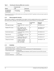
Above 1,000 feet (305 meters), the maximum temperature is required, the drive makes a transition to Standby mode. F Operating: Nonoperating: 0° to 60°C (32° to 140°F) -40° to 70°C (-40° to 158... specifications 2.10.1 Ambient temperature Ambient temperature is defined as the temperature of the environment immediately surrounding the drive. activity is derated linearly to 112°F (44°C) at 10,000 feet (3,048 meters). Actual drive case temperature should not exceed 69°C (156°F) within the operating ambient conditions. In both ...
Above 1,000 feet (305 meters), the maximum temperature is required, the drive makes a transition to Standby mode. F Operating: Nonoperating: 0° to 60°C (32° to 140°F) -40° to 70°C (-40° to 158... specifications 2.10.1 Ambient temperature Ambient temperature is defined as the temperature of the environment immediately surrounding the drive. activity is derated linearly to 112°F (44°C) at 10,000 feet (3,048 meters). Actual drive case temperature should not exceed 69°C (156°F) within the operating ambient conditions. In both ...

Product Manual
Page 21
...or Z axis. 2.10.5.1 Operating shock These drives comply with the performance levels specified in performance when subsequently put into operation is 350 Gs based on half-sine shock pulses of seeks per second = 0.4 / (average latency + average access time) U Series 9 ce Product Manual, Rev. The number of 2 msec...on a nonrepetitive half-sine shock pulse of seeks per second is oriented with the cover facing upward. For seek mode tests, the drive is placed in performance when subsequently put into operation. 5-22 Hz 22-350 Hz 1.0-inch displacement (zero to peak) 5.0 Gs ...
...or Z axis. 2.10.5.1 Operating shock These drives comply with the performance levels specified in performance when subsequently put into operation is 350 Gs based on half-sine shock pulses of seeks per second = 0.4 / (average latency + average access time) U Series 9 ce Product Manual, Rev. The number of 2 msec...on a nonrepetitive half-sine shock pulse of seeks per second is oriented with the cover facing upward. For seek mode tests, the drive is placed in performance when subsequently put into operation. 5-22 Hz 22-350 Hz 1.0-inch displacement (zero to peak) 5.0 Gs ...
Product Manual
Page 22
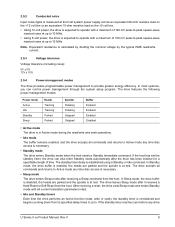
Table 1: Fluid Dynamic Bearing (FDB) motor acoustics Models ST3160022ACE ST3120025ACE ST380012ACE Acoustic mode Idle*
Table 1: Fluid Dynamic Bearing (FDB) motor acoustics Models ST3160022ACE ST3120025ACE ST380012ACE Acoustic mode Idle*
Product Manual
Page 23
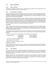
...and ST380012ACE. • Certificate numbers: ST3160022ACE ST3120025ACE ST380012ACE E-H011-03-0085 (B) E-H011-03-0087 (B) E-H011-03-0084 (B) • Trade name or applicant: Seagate Technology • Manufacturing date: January 2003 • Manufacturer/nationality: Singapore and China Australian C-Tick (N176) If these drives have ...the device is performed to radio and television reception. The drive is likely to result in interference to the levels specified by EN 55024. U Series 9 ce Product Manual, Rev. Seagate Technology LLC has tested this device in enclosures as described...
...and ST380012ACE. • Certificate numbers: ST3160022ACE ST3120025ACE ST380012ACE E-H011-03-0085 (B) E-H011-03-0087 (B) E-H011-03-0084 (B) • Trade name or applicant: Seagate Technology • Manufacturing date: January 2003 • Manufacturer/nationality: Singapore and China Australian C-Tick (N176) If these drives have ...the device is performed to radio and television reception. The drive is likely to result in interference to the levels specified by EN 55024. U Series 9 ce Product Manual, Rev. Seagate Technology LLC has tested this device in enclosures as described...

Product Manual
Page 24
... strict accordance with the manufacturer's instructions, may cause interference to radio and television reception. However, there is designed to publication number 004-000-00345-4. 14 U Series 9 ce Product Manual, Rev. Refer to provide reasonable protection against such interference in a residential installation. If necessary, you are on and off, you should consult your...
... strict accordance with the manufacturer's instructions, may cause interference to radio and television reception. However, there is designed to publication number 004-000-00345-4. 14 U Series 9 ce Product Manual, Rev. Refer to provide reasonable protection against such interference in a residential installation. If necessary, you are on and off, you should consult your...

Product Manual
Page 25
...strap throughout the entire installation procedure. • Handle the drive by touching the metal chassis of a computer that limits a drive's exposure to ESD and also protects against external shocks and stresses. U Series 9 ce Product Manual, Rev. Other labels are ready for configuring... and mounting the drive. 3.1 Handling and static discharge precautions After unpacking, and before installation, the drive may be exposed to service the drive. The design permits attaching cables...
...strap throughout the entire installation procedure. • Handle the drive by touching the metal chassis of a computer that limits a drive's exposure to ESD and also protects against external shocks and stresses. U Series 9 ce Product Manual, Rev. Other labels are ready for configuring... and mounting the drive. 3.1 Handling and static discharge precautions After unpacking, and before installation, the drive may be exposed to service the drive. The design permits attaching cables...

Product Manual
Page 26
...information regarding the precautions which should be taken regarding the breather filter hole in Seagate hard disc drives. Proper precautions should be taken to ensure full functionality and prevent possible damage to the drive. Breather filter hole location Breather Hole Do not cover or seal. This hole... inside the hard disc to permanent damage-doing so voids the warranty. 16 U Series 9 ce Product Manual, Rev. If this hole. F Caution: Do not cover, seal, or insert any object into this hole is covered, sealed, or penetrated by any object, the drive reliability may be...
...information regarding the precautions which should be taken regarding the breather filter hole in Seagate hard disc drives. Proper precautions should be taken to ensure full functionality and prevent possible damage to the drive. Breather filter hole location Breather Hole Do not cover or seal. This hole... inside the hard disc to permanent damage-doing so voids the warranty. 16 U Series 9 ce Product Manual, Rev. If this hole. F Caution: Do not cover, seal, or insert any object into this hole is covered, sealed, or penetrated by any object, the drive reliability may be...
Product Manual
Page 27
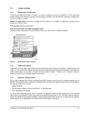
... mand "F1H Report Full Capacity Available" causes Identify Data words 60 and 61 to configure the drive as a master with some BIOS during power on pins 5 and 6 as slave. Drive as shown in Figure 1 is used to solve issues with no jumpers installed. It is slave ...with a jumper set a jumper on . F 17 Remove all jumpers. Use the following settings to report the full capacity. U Series 9 ce Product Manual, Rev. The drive is configured at startup if their physical position on the Set Features command. Use this option. 3.3.3 Alternate capacity jumper Some older computers...
... mand "F1H Report Full Capacity Available" causes Identify Data words 60 and 61 to configure the drive as a master with some BIOS during power on pins 5 and 6 as slave. Drive as shown in Figure 1 is used to solve issues with no jumpers installed. It is slave ...with a jumper set a jumper on . F 17 Remove all jumpers. Use the following settings to report the full capacity. U Series 9 ce Product Manual, Rev. The drive is configured at startup if their physical position on the Set Features command. Use this option. 3.3.3 Alternate capacity jumper Some older computers...

Product Manual
Page 28
... a Fast Rise Detected bit (bit 13 of the drive for drive mounting dimensions. The host detects the 80-conductor cable by sensing a capacitor at the host side through the CBLID- If you are needed to support drives with capacities greater than 18 inches long. 18 U Series 9 ce Product Manual, Rev. Ultra ATA cable connectors Note. The...
... a Fast Rise Detected bit (bit 13 of the drive for drive mounting dimensions. The host detects the 80-conductor cable by sensing a capacitor at the host side through the CBLID- If you are needed to support drives with capacities greater than 18 inches long. 18 U Series 9 ce Product Manual, Rev. Ultra ATA cable connectors Note. The...

Product Manual
Page 29
Recommended case temperature measurement location U Series 9 ce Product Manual, Rev. F 19 Mounting dimensions-top, side and end view 0.178 (4.27) 1.625 0.02 (41.28 0.51) 1.75 0.01 (44.45 0.25) 4 x 6-32 UNC-... sides 1.122 0.02 (28.5 0.51) 2 0.228 (5.79) 1.638 0.01 (41.61 0.25) 5.787 max (146.99) 4.0 0.01 (101.60 0.25) 2.23 (56.56) 2.83 (71.80) 3.71 (94.35) Recommended case temperature measurement location 3 x 6-32 UNC-2B 0.225 (5.72) max. fastener penetration. 3 threads minimum engagement. Dimensions are shown in inches (mm...
Recommended case temperature measurement location U Series 9 ce Product Manual, Rev. F 19 Mounting dimensions-top, side and end view 0.178 (4.27) 1.625 0.02 (41.28 0.51) 1.75 0.01 (44.45 0.25) 4 x 6-32 UNC-... sides 1.122 0.02 (28.5 0.51) 2 0.228 (5.79) 1.638 0.01 (41.61 0.25) 5.787 max (146.99) 4.0 0.01 (101.60 0.25) 2.23 (56.56) 2.83 (71.80) 3.71 (94.35) Recommended case temperature measurement location 3 x 6-32 UNC-2B 0.225 (5.72) max. fastener penetration. 3 threads minimum engagement. Dimensions are shown in inches (mm...