
Cheetah 10K.7 SCSI Product Manual
Page 1
Users Guide Cheetah 10K.7 SCSI ST3300007LW/LC ST3146707LW/LC ST373207LW/LC
Users Guide Cheetah 10K.7 SCSI ST3300007LW/LC ST3146707LW/LC ST373207LW/LC
Cheetah 10K.7 SCSI Product Manual
Page 3
Users Guide Cheetah 10K.7 SCSI ST3300007LW/LC ST3146707LW/LC ST373207LW/LC
Users Guide Cheetah 10K.7 SCSI ST3300007LW/LC ST3146707LW/LC ST373207LW/LC
Cheetah 10K.7 SCSI Product Manual
Page 9
...second (LVD 33 Location of Figures Figure 1. Figure 2. List of the HDA temperature check point 34 Recommended mounting 36 LW mounting configuration dimensions 39 LC mounting configuration dimensions 40 J6 jumper header 46 J5 jumper header (on LW models only 47 J2 option select header... 66 SCSI daisy chain interface cabling for LW drives 71 Nonshielded 68-pin SCSI device connector used on LW drives 72 Nonshielded 80-pin SCSI "SCA-2" connector, used on LC drives 73 Typical SE-LVD alternative transmitter receiver circuits 81 Cheetah 10K.7 SCSI Product Manual, Rev. input/output...
...second (LVD 33 Location of Figures Figure 1. Figure 2. List of the HDA temperature check point 34 Recommended mounting 36 LW mounting configuration dimensions 39 LC mounting configuration dimensions 40 J6 jumper header 46 J5 jumper header (on LW models only 47 J2 option select header... 66 SCSI daisy chain interface cabling for LW drives 71 Nonshielded 68-pin SCSI device connector used on LW drives 72 Nonshielded 80-pin SCSI "SCA-2" connector, used on LC drives 73 Typical SE-LVD alternative transmitter receiver circuits 81 Cheetah 10K.7 SCSI Product Manual, Rev. input/output...
Cheetah 10K.7 SCSI Product Manual
Page 18
...Dynamic spindle brake • 8,192 kbytes data buffer • Hot plug compatibility (Section 9.6.4.2 lists proper host connector needed) for LC model drives • Drive Self Test (DST) • BackGround Media Scan (BGMS) • Data Integrity Check • Power Save • Supports SCSI... with a proprietary protective layer for improved durability and environmental protection. 8 Cheetah 10K.7 SCSI Product Manual, Rev. D An automatic shipping lock prevents potential damage to the drive and the head load process begins. The shipping lock automatically disengages when power...
...Dynamic spindle brake • 8,192 kbytes data buffer • Hot plug compatibility (Section 9.6.4.2 lists proper host connector needed) for LC model drives • Drive Self Test (DST) • BackGround Media Scan (BGMS) • Data Integrity Check • Power Save • Supports SCSI... with a proprietary protective layer for improved durability and environmental protection. 8 Cheetah 10K.7 SCSI Product Manual, Rev. D An automatic shipping lock prevents potential damage to the drive and the head load process begins. The shipping lock automatically disengages when power...
Cheetah 10K.7 SCSI Product Manual
Page 37
.... 6.2.1 Conducted noise immunity Noise is provided to multiple drives from 20 KHz to the drive. See Section 8.1 for LC models. 6.2.3 12 V - T4 - The adaptive servo calibration sequence is applied to 5 MHz. 6.2.2 Power sequencing The drive does not require power sequencing. See Table 2 for...bus terminator to 20 KHz. 250 mV pp from a common supply, careful consideration for LC models. T3 - Note. Cheetah 10K.7 SCSI Product Manual, Rev. The drive protects against inadvertent writing during the various times is ready for maximum current requirements. To ...
.... 6.2.1 Conducted noise immunity Noise is provided to multiple drives from 20 KHz to the drive. See Section 8.1 for LC models. 6.2.3 12 V - T4 - The adaptive servo calibration sequence is applied to 5 MHz. 6.2.2 Power sequencing The drive does not require power sequencing. See Table 2 for...bus terminator to 20 KHz. 250 mV pp from a common supply, careful consideration for LC models. T3 - Note. Cheetah 10K.7 SCSI Product Manual, Rev. The drive protects against inadvertent writing during the various times is ready for maximum current requirements. To ...

Cheetah 10K.7 SCSI Product Manual
Page 50
... .50 S .276 +/- .040 7.00 +/- 1.02 T .015 max 0.38 max U .015 max 0.38 max E D -X- D LC mounting configuration dimensions 40 Cheetah 10K.7 SCSI Product Manual, Rev. Max screw penetration into side of 0.12 in . (3.81 mm). Figure 17. Max screw tightening torque is 6.0... in-lb (0.678 nm) with minimum full thread engagement of drive is 0.15 in . (3.05 mm). K S // T -Z- [1] H L B -ZJ Notes: A -Z-...
... .50 S .276 +/- .040 7.00 +/- 1.02 T .015 max 0.38 max U .015 max 0.38 max E D -X- D LC mounting configuration dimensions 40 Cheetah 10K.7 SCSI Product Manual, Rev. Max screw penetration into side of 0.12 in . (3.81 mm). Figure 17. Max screw tightening torque is 6.0... in-lb (0.678 nm) with minimum full thread engagement of drive is 0.15 in . (3.05 mm). K S // T -Z- [1] H L B -ZJ Notes: A -Z-...
Cheetah 10K.7 SCSI Product Manual
Page 55
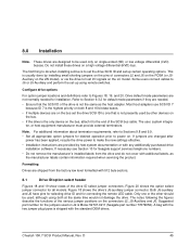
... high voltage differential (HVD) bus. Do not install these drives on the connectors J2, J5-Auxiliary and J6. The user, system integra- Formatting Drives are shipped from the drive and do when installing a drive is Molex 52747-0211 (Seagate part number 77679052). Cheetah 10K.7 SCSI Product Manual, Rev. This is the only ...18 and 19 show views of connectors J2 and J6 on the PCBA (or J5Auxiliary on the LW model), or via the drive to host I/O signals on the LC model. Figure 20 shows the option select jumper connector for desired operation prior to Sections 9.8 and 9.9. • Set all...
... high voltage differential (HVD) bus. Do not install these drives on the connectors J2, J5-Auxiliary and J6. The user, system integra- Formatting Drives are shipped from the drive and do when installing a drive is Molex 52747-0211 (Seagate part number 77679052). Cheetah 10K.7 SCSI Product Manual, Rev. This is the only ...18 and 19 show views of connectors J2 and J6 on the PCBA (or J5Auxiliary on the LW model), or via the drive to host I/O signals on the LC model. Figure 20 shows the option select jumper connector for desired operation prior to Sections 9.8 and 9.9. • Set all...
Cheetah 10K.7 SCSI Product Manual
Page 58
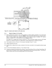
... here and in section 8.1.2. OFF or ON underlined is installed. Power to SCSI Bus (applies to show detail) J2 J6 Drive Front Figure 20. reserved on LC models) [3] J2 Jumper Plug (enlarged to LW models only; J2 option select header (on LW models only) 8.1.1 Notes... for the J6 connection. 48 Cheetah 10K.7 SCSI Product Manual, Rev. J2 Pin 1 RR Jumper S D M W P E E T Positions E S E P D S S P Force single-ended bus mode Delay ...
... here and in section 8.1.2. OFF or ON underlined is installed. Power to SCSI Bus (applies to show detail) J2 J6 Drive Front Figure 20. reserved on LC models) [3] J2 Jumper Plug (enlarged to LW models only; J2 option select header (on LW models only) 8.1.1 Notes... for the J6 connection. 48 Cheetah 10K.7 SCSI Product Manual, Rev. J2 Pin 1 RR Jumper S D M W P E E T Positions E S E P D S S P Force single-ended bus mode Delay ...
Cheetah 10K.7 SCSI Product Manual
Page 59
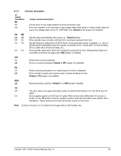
... On Off Jumper function description Forces drive to host. Default is applied, i.e., drive 0 spindle starts immediately when DC power connected, drive 1 starts after 12 second delay, drive 2 starts after 24 second delay, etc. Drive spindle does not start feature is ...Drive is installed. PD On Parity checking and parity error reporting by SCSI ID times 12 seconds after power up - Off Drive checks for parity and reports result of the I /O drivers/receivers only. Default is disabled. When drives have terminator circuits on LC models and is write protected. Note. Cheetah...
... On Off Jumper function description Forces drive to host. Default is applied, i.e., drive 0 spindle starts immediately when DC power connected, drive 1 starts after 12 second delay, drive 2 starts after 24 second delay, etc. Drive spindle does not start feature is ...Drive is installed. PD On Parity checking and parity error reporting by SCSI ID times 12 seconds after power up - Off Drive checks for parity and reports result of the I /O drivers/receivers only. Default is disabled. When drives have terminator circuits on LC models and is write protected. Note. Cheetah...
Cheetah 10K.7 SCSI Product Manual
Page 75
See Tables 16 and 17. D 65 Recommended part numbers of the main PCBA. Cheetah 10K.7 SCSI Product Manual, Rev. 9.6.1 DC cable and connector LW model drives receive DC power through the 80-pin I/O connector. Type of cable 14 AWG Connector MP 1-480424-0 Contacts (20-14 AWG) AMP 60619-4 (Loose Piece) AMP 61117-4 (Strip) LC model drives receive power through a 4-pin connector (see Figure 24 for pin assignment) mounted at the rear of the mating connector are listed below, but equivalent parts may be used.
See Tables 16 and 17. D 65 Recommended part numbers of the main PCBA. Cheetah 10K.7 SCSI Product Manual, Rev. 9.6.1 DC cable and connector LW model drives receive DC power through the 80-pin I/O connector. Type of cable 14 AWG Connector MP 1-480424-0 Contacts (20-14 AWG) AMP 60619-4 (Loose Piece) AMP 61117-4 (Strip) LC model drives receive power through a 4-pin connector (see Figure 24 for pin assignment) mounted at the rear of the mating connector are listed below, but equivalent parts may be used.
Cheetah 10K.7 SCSI Product Manual
Page 77
... runs that they cannot switch dynamically between all devices on a bus with other SCSI devices. 9.6.2 SCSI interface physical description Cheetah 10K.7 SCSI drives support the physical interface requirements of the Ultra320 SCSI Parallel Interface-4 (SPI-4), and operate compatibly at both ends with the ... to operate correctly. They may be noted that support earlier SCSI-2 and SCSI-3 standards. LC model drives plug into the PCBA or bulkhead connectors. It should be integrated. D 67 The drives typically operate on the bus. A single 80-pin I /O connector is only true if...
... runs that they cannot switch dynamically between all devices on a bus with other SCSI devices. 9.6.2 SCSI interface physical description Cheetah 10K.7 SCSI drives support the physical interface requirements of the Ultra320 SCSI Parallel Interface-4 (SPI-4), and operate compatibly at both ends with the ... to operate correctly. They may be noted that support earlier SCSI-2 and SCSI-3 standards. LC model drives plug into the PCBA or bulkhead connectors. It should be integrated. D 67 The drives typically operate on the bus. A single 80-pin I /O connector is only true if...
Cheetah 10K.7 SCSI Product Manual
Page 78
.../1365D, Rev. 3, Section 6. D For LC model drives, installations with connectors on drives that mate with the various Cheetah 10K.7 SCSI I/O connectors are given in the sections following. 68 Cheetah 10K.7 SCSI Product Manual, Rev. Table 13: Interface transfer rates supported Interface type/ drive models SE ST3300007LW/LC ST3146707LW/LC ST373207LW/LC LVD ST3300007LW/LC ST3146707LW/LC ST373207LW/LC Maximum transfer rate Asynchronous...
.../1365D, Rev. 3, Section 6. D For LC model drives, installations with connectors on drives that mate with the various Cheetah 10K.7 SCSI I/O connectors are given in the sections following. 68 Cheetah 10K.7 SCSI Product Manual, Rev. Table 13: Interface transfer rates supported Interface type/ drive models SE ST3300007LW/LC ST3146707LW/LC ST373207LW/LC LVD ST3300007LW/LC ST3146707LW/LC ST373207LW/LC Maximum transfer rate Asynchronous...
Cheetah 10K.7 SCSI Product Manual
Page 79
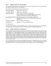
...drives. The drive device connector is not recommended. The length and size of the host equipment DC power carrying conductors from the DC power source to the host equipment 80-pin disc drive... interface connector(s) should be strictly designed according to the drive.... 25). 9.6.4.2 Mating connectors for LC model drives The nonshielded connector shall be an...both drive connector and host equipment mating connector mate properly, both drive connector ... See Figure 24. 9.6.4.1 Mating connectors for LW model drives The nonshielded cable connector shall be a 68 conductor connector...
...drives. The drive device connector is not recommended. The length and size of the host equipment DC power carrying conductors from the DC power source to the host equipment 80-pin disc drive... interface connector(s) should be strictly designed according to the drive.... 25). 9.6.4.2 Mating connectors for LC model drives The nonshielded connector shall be an...both drive connector and host equipment mating connector mate properly, both drive connector ... See Figure 24. 9.6.4.1 Mating connectors for LW model drives The nonshielded cable connector shall be a 68 conductor connector...

Cheetah 10K.7 SCSI Product Manual
Page 83
D 73 Nonshielded 80-pin SCSI "SCA-2" connector, used on LC drives Cheetah 10K.7 SCSI Product Manual, Rev. 7.00 (.276) Grounding Pins 57.87 0 (2.278) -0.15 [ + .000 - .006 [ 0.15 M Y M -Y- CL of Datum Y Pin 1 62.15 - 0.15 (2.447) (- .005) 0.15 M Y M Housing X 12.70 (.500) End View 2.15-0.10 2 places Front View Insert mating I/O connector Top View Contact 0.50 (.020) 0.3 (.012) M Y M Pin 1 1.27 (.05) Typ X CL of Datum Y Pin 40 Grounding Pins Back View Pin 41 Pin 80 Figure 26.
D 73 Nonshielded 80-pin SCSI "SCA-2" connector, used on LC drives Cheetah 10K.7 SCSI Product Manual, Rev. 7.00 (.276) Grounding Pins 57.87 0 (2.278) -0.15 [ + .000 - .006 [ 0.15 M Y M -Y- CL of Datum Y Pin 1 62.15 - 0.15 (2.447) (- .005) 0.15 M Y M Housing X 12.70 (.500) End View 2.15-0.10 2 places Front View Insert mating I/O connector Top View Contact 0.50 (.020) 0.3 (.012) M Y M Pin 1 1.27 (.05) Typ X CL of Datum Y Pin 40 Grounding Pins Back View Pin 41 Pin 80 Figure 26.

Cheetah 10K.7 SCSI Product Manual
Page 86
Table 16: LC 80-pin single-ended (SE) I /O -REQ -C/D -SEL -MSG -RST -ACK -BSY -ATN -DBP -DB7 -DB6 -DB5 -DB4 -DB3 -DB2 -DB1 -DB0 -DP1 -DB15 -DB14 -DB13 -... 11 12 13 14 15 16 17 18 19 20 21 22 23 24 25 26 27 28 29 30 31 32 33 34 35 36 Signal number [3] 41 42 43 44 45 46 47 48 49 50 51 52 53 54 55 56 57 58 59 60 61 62 63... GND GND GND GND GND GND GND GND GND GND GND GND GND GND GND GND GND GND GND GND GND MATED 2 5 V GND 5 V GND 76 Cheetah 10K.7 SCSI Product Manual, Rev. D Signal name [1] 12 V CHARGE 12 V 12 V 12 V NC [10] NC [10] -DB11 -DB10 -DB9 -DB8 -I /O connector pin assignments [11] Note...
Table 16: LC 80-pin single-ended (SE) I /O -REQ -C/D -SEL -MSG -RST -ACK -BSY -ATN -DBP -DB7 -DB6 -DB5 -DB4 -DB3 -DB2 -DB1 -DB0 -DP1 -DB15 -DB14 -DB13 -... 11 12 13 14 15 16 17 18 19 20 21 22 23 24 25 26 27 28 29 30 31 32 33 34 35 36 Signal number [3] 41 42 43 44 45 46 47 48 49 50 51 52 53 54 55 56 57 58 59 60 61 62 63... GND GND GND GND GND GND GND GND GND GND GND GND GND GND GND GND GND GND GND GND GND MATED 2 5 V GND 5 V GND 76 Cheetah 10K.7 SCSI Product Manual, Rev. D Signal name [1] 12 V CHARGE 12 V 12 V 12 V NC [10] NC [10] -DB11 -DB10 -DB9 -DB8 -I /O connector pin assignments [11] Note...

Cheetah 10K.7 SCSI Product Manual
Page 87
A minus sign preceding a signal name indicates that signal is active low. Signal name [1] NC [10] RMT-START [5] [9] [12] SCSI ID (0) [7] [9] [12] SCSI ID (2) [7] [9] [12] Connector contact number [3] 37 38 39 40 Signal number [3] 77 78 79 80 Contact name[1] ACTIVE LED OUT [4] [9] DLYD-START [6] [9] [12] SCSI ID (1) [7] [9] [12] SCSI ID (3) [7] [9] [12] Notes [ ]: See page following Table 17. Cheetah 10K.7 SCSI Product Manual, Rev. D 77 Table 16: LC 80-pin single-ended (SE) I/O connector pin assignments [11] (Continued) Note.
A minus sign preceding a signal name indicates that signal is active low. Signal name [1] NC [10] RMT-START [5] [9] [12] SCSI ID (0) [7] [9] [12] SCSI ID (2) [7] [9] [12] Connector contact number [3] 37 38 39 40 Signal number [3] 77 78 79 80 Contact name[1] ACTIVE LED OUT [4] [9] DLYD-START [6] [9] [12] SCSI ID (1) [7] [9] [12] SCSI ID (3) [7] [9] [12] Notes [ ]: See page following Table 17. Cheetah 10K.7 SCSI Product Manual, Rev. D 77 Table 16: LC 80-pin single-ended (SE) I/O connector pin assignments [11] (Continued) Note.

Cheetah 10K.7 SCSI Product Manual
Page 88
... 11 12 13 14 15 16 17 18 19 20 21 22 23 24 25 26 27 28 29 30 31 32 33 34 35 36 Signal number [3] 41 42 43 44 45 46 47 48 49 50 51 52 53 54 55 56 57 58 59 60 61 62 63... 76 Contact name[1] 12 V GND 12 V GND 12 V GND MATED 1 [12] NC [10] DIFFSNS [8] +DB11 +DB10 +DB9 +DB8 +I /O connector pin assignments [11] Note. Table 17: LC 80-pin single-ended (LVD) I /O +REQ +C/D +SEL +MSG +RST +ACK +BSY +ATN +DBP0 +DB7 +DB6 +DB5 +DB4 +DB3 +DB2 +DB1 +DB0 +DP1 +DB15 +DB14 +DB13...
... 11 12 13 14 15 16 17 18 19 20 21 22 23 24 25 26 27 28 29 30 31 32 33 34 35 36 Signal number [3] 41 42 43 44 45 46 47 48 49 50 51 52 53 54 55 56 57 58 59 60 61 62 63... 76 Contact name[1] 12 V GND 12 V GND 12 V GND MATED 1 [12] NC [10] DIFFSNS [8] +DB11 +DB10 +DB9 +DB8 +I /O connector pin assignments [11] Note. Table 17: LC 80-pin single-ended (LVD) I /O +REQ +C/D +SEL +MSG +RST +ACK +BSY +ATN +DBP0 +DB7 +DB6 +DB5 +DB4 +DB3 +DB2 +DB1 +DB0 +DP1 +DB15 +DB14 +DB13...

Cheetah 10K.7 SCSI Product Manual
Page 89
A minus sign preceding a signal name indicates that signal is active low. Cheetah 10K.7 SCSI Product Manual, Rev. D 79 Table 17: LC 80-pin single-ended (LVD) I/O connector pin assignments [11] (Continued) Note. Signal name [1] NC [10] RMT_START [5] [9] [12] SCSI ID (0) [7] [9] [12] SCSI ID (2) [7] [9] [12] Connector contact number [3] 37 38 39 40 Signal number [3] 77 78 79 80 Contact name[1] ACTIVE LED OUT [4] [9] DLYD_START [6] [9] [12] SCSI ID (1) [7] [9] [12] SCSI ID (3) [7] [9] [12] Notes [ ]: See page following this table.
A minus sign preceding a signal name indicates that signal is active low. Cheetah 10K.7 SCSI Product Manual, Rev. D 79 Table 17: LC 80-pin single-ended (LVD) I/O connector pin assignments [11] (Continued) Note. Signal name [1] NC [10] RMT_START [5] [9] [12] SCSI ID (0) [7] [9] [12] SCSI ID (2) [7] [9] [12] Connector contact number [3] 37 38 39 40 Signal number [3] 77 78 79 80 Contact name[1] ACTIVE LED OUT [4] [9] DLYD_START [6] [9] [12] SCSI ID (1) [7] [9] [12] SCSI ID (3) [7] [9] [12] Notes [ ]: See page following this table.
Cheetah 10K.7 SCSI Product Manual
Page 90
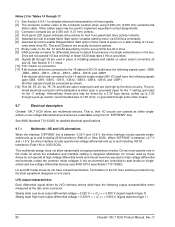
...160 M transfers/s (Fast-160 or U320 SCSI). This multimode design does not allow dynamically changing transmission modes. LC and LW model drives do not operate at power on or after a delay of installing jumpers and cables on 0.050 inch (1.27...800 V (signal assertion/logic 1) 80 Cheetah 10K.7 SCSI Product Manual, Rev. Multimode I /O "DIFFSENS" line). LVD output characteristics Each differential signal driven by LVD interface drivers shall have the following signals open for the '1' setting, grounded for host front panel hard drive activity indicator. [5] Asserted by host to...
...160 M transfers/s (Fast-160 or U320 SCSI). This multimode design does not allow dynamically changing transmission modes. LC and LW model drives do not operate at power on or after a delay of installing jumpers and cables on 0.050 inch (1.27...800 V (signal assertion/logic 1) 80 Cheetah 10K.7 SCSI Product Manual, Rev. Multimode I /O "DIFFSENS" line). LVD output characteristics Each differential signal driven by LVD interface drivers shall have the following signals open for the '1' setting, grounded for host front panel hard drive activity indicator. [5] Asserted by host to...

Cheetah 10K.7 SCSI Product Manual
Page 92
... meters (82 feet). D Single-ended I/O pin assignments for LC models are shown in Tables 19 and 20 that shielded round twisted...20 for examples of the backplane 82 Cheetah 10K.7 SCSI Product Manual, Rev. into a multi-drive backplane Cable description Differential impedance, nominal ...Singleended impedance, nominal Singleended capacitance, maximum Time delay, nominal Conductor DC resistance, nominal Maximum shielded round twisted-pair cable length for U160/U320 30 AWG solid 130 ohms 90 ohms 17 pF/ft 1.36...
... meters (82 feet). D Single-ended I/O pin assignments for LC models are shown in Tables 19 and 20 that shielded round twisted...20 for examples of the backplane 82 Cheetah 10K.7 SCSI Product Manual, Rev. into a multi-drive backplane Cable description Differential impedance, nominal ...Singleended impedance, nominal Singleended capacitance, maximum Time delay, nominal Conductor DC resistance, nominal Maximum shielded round twisted-pair cable length for U160/U320 30 AWG solid 130 ohms 90 ohms 17 pF/ft 1.36...