
Product Manual
Page 5
...and 1012 Product Manual iii Contents Introduction 1 Specification summary table 2 1.0 Drive specifications 5 1.1 Formatted capacity 5 1.1.1 Default logical geometry 5 1.1.2 Supported CHS translation geometries 6 1.2 Physical organization 6 1.3 Recording and interface technology 6 1.4 Physical characteristics 7 1.5 Seek time 7 1.6 Start/stop times 8 1.7 Power Specifications 8 1.7.1 Power consumption 8 1.7.2 Conducted noise 11 1.7.3 Voltage tolerance 11 1.7.4 Power-management modes 11 1.8 Environmental tolerances 12 1.8.1 Ambient temperature 12 1.8.2 Temperature gradient 12...
...and 1012 Product Manual iii Contents Introduction 1 Specification summary table 2 1.0 Drive specifications 5 1.1 Formatted capacity 5 1.1.1 Default logical geometry 5 1.1.2 Supported CHS translation geometries 6 1.2 Physical organization 6 1.3 Recording and interface technology 6 1.4 Physical characteristics 7 1.5 Seek time 7 1.6 Start/stop times 8 1.7 Power Specifications 8 1.7.1 Power consumption 8 1.7.2 Conducted noise 11 1.7.3 Voltage tolerance 11 1.7.4 Power-management modes 11 1.8 Environmental tolerances 12 1.8.1 Ambient temperature 12 1.8.2 Temperature gradient 12...
Product Manual
Page 6
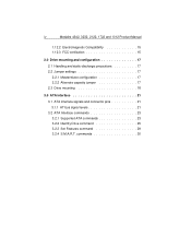
iv Medalist 4342, 3232, 2122, 1722 and 1012 Product Manual 1.12.2 Electromagnetic Compatibility 15 1.12.3 FCC verification 15 2.0 Drive mounting and configuration 17 2.1 Handling and static-discharge precautions 17 2.2 Jumper settings 17 2.2.1 Master/slave configuration 17 2.2.2 Alternate capacity jumper 17 2.3 Drive mounting 18 3.0 ATA interface 21 3.1 ATA interface signals and connector pins 21 3.1.1 AT bus signal levels 21 3.2 ATA Interface commands 23 3.2.1 Supported ATA commands 23 3.2.2 Identify Drive command 25 3.2.3 Set Features command 29 3.2.4 S.M.A.R.T. commands ...
iv Medalist 4342, 3232, 2122, 1722 and 1012 Product Manual 1.12.2 Electromagnetic Compatibility 15 1.12.3 FCC verification 15 2.0 Drive mounting and configuration 17 2.1 Handling and static-discharge precautions 17 2.2 Jumper settings 17 2.2.1 Master/slave configuration 17 2.2.2 Alternate capacity jumper 17 2.3 Drive mounting 18 3.0 ATA interface 21 3.1 ATA interface signals and connector pins 21 3.1.1 AT bus signal levels 21 3.2 ATA Interface commands 23 3.2.1 Supported ATA commands 23 3.2.2 Identify Drive command 25 3.2.3 Set Features command 29 3.2.4 S.M.A.R.T. commands ...
Product Manual
Page 9
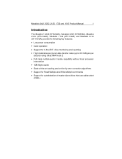
... and 1012 Product Manual 1 Introduction The Medalist® 4342 (ST34342A), Medalist 3232 (ST33232A), Medalist 2122 (ST32122A), Medalist 1722 (ST31722A) and Medalist 1012 (ST31012A) provide the following key features: • Low power consumption • Quiet operation • Support for autodetection of master/slave drives that use cable select (CSEL) drive monitoring and reporting • High instantaneous (burst) data-transfer rates (up to 33.3 Mbytes per second) using Ultra DMA mode 2 • Full-track multiple-sector transfer capability...
... and 1012 Product Manual 1 Introduction The Medalist® 4342 (ST34342A), Medalist 3232 (ST33232A), Medalist 2122 (ST32122A), Medalist 1722 (ST31722A) and Medalist 1012 (ST31012A) provide the following key features: • Low power consumption • Quiet operation • Support for autodetection of master/slave drives that use cable select (CSEL) drive monitoring and reporting • High instantaneous (burst) data-transfer rates (up to 33.3 Mbytes per second) using Ultra DMA mode 2 • Full-track multiple-sector transfer capability...
Product Manual
Page 10
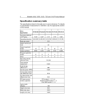
...Physical read/write heads 8 6 4 4 2 Discs 4 3 2 2 1 Recording density (bits/inch max) 115,100 Track density (tracks/inch) 5,950 Areal density (Mbits/inch2) 685 Spindle speed (RPM) 4,500 Internal data-transfer rate (Mbits/sec max) 87.8 I/O data-transfer rate (Mbytes/sec max) 33.3 ATA data-transfer modes supported PIO modes 0, 1, 2, 3, 4; Multiword DMA modes 0, 1, 2 Ultra DMA modes 0, 1, 2 Cache buffer (Kbytes) 128 Height (mm max) 26.2 Width (mm max) 102.4 Length (mm max) 146.8 2 Medalist 4342, 3232, 2122, 1722 and 1012 Product Manual Specification summary...
...Physical read/write heads 8 6 4 4 2 Discs 4 3 2 2 1 Recording density (bits/inch max) 115,100 Track density (tracks/inch) 5,950 Areal density (Mbits/inch2) 685 Spindle speed (RPM) 4,500 Internal data-transfer rate (Mbits/sec max) 87.8 I/O data-transfer rate (Mbytes/sec max) 33.3 ATA data-transfer modes supported PIO modes 0, 1, 2, 3, 4; Multiword DMA modes 0, 1, 2 Ultra DMA modes 0, 1, 2 Cache buffer (Kbytes) 128 Height (mm max) 26.2 Width (mm max) 102.4 Length (mm max) 146.8 2 Medalist 4342, 3232, 2122, 1722 and 1012 Product Manual Specification summary...
Product Manual
Page 12
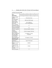
... bits read 300,000 40,000 5 4 Medalist 4342, 3232, 2122, 1722 and 1012 Product Manual continued from previous page Drive Specification ST34342A ST33232A ST32122A ST31722A ST31012A Relative humidity gradient Wet bulb temperature (°C max) Altitude (meters above mean sea level, max) Shock, operating (Gs max at 11 msec) Shock, nonoperating (Gs max at 11 msec) Vibration, operating Vibration, nonoperating Drive acoustics (bels-sound power) Idle mode (dBA...
... bits read 300,000 40,000 5 4 Medalist 4342, 3232, 2122, 1722 and 1012 Product Manual continued from previous page Drive Specification ST34342A ST33232A ST32122A ST31722A ST31012A Relative humidity gradient Wet bulb temperature (°C max) Altitude (meters above mean sea level, max) Shock, operating (Gs max at 11 msec) Shock, nonoperating (Gs max at 11 msec) Vibration, operating Vibration, nonoperating Drive acoustics (bels-sound power) Idle mode (dBA...
Product Manual
Page 13
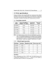
... 2,114,784 512 Note. Medalist 4342, 3232, 2122, 1722 and 1012 Product Manual 5 1.0 Drive specifications Unless otherwise noted, all blocks (sectors) are measured under ambient conditions, at 25°C, and nominal power. For convenience, the phrases the drive and this drive are used throughout this manual to n - 1, where n is configured for LBA addressing or for details. 1.1.1 Default logical geometry CHS Mode Cylinders Read/Write heads Sectors per track ST34342A 8,894 15...
... 2,114,784 512 Note. Medalist 4342, 3232, 2122, 1722 and 1012 Product Manual 5 1.0 Drive specifications Unless otherwise noted, all blocks (sectors) are measured under ambient conditions, at 25°C, and nominal power. For convenience, the phrases the drive and this drive are used throughout this manual to n - 1, where n is configured for LBA addressing or for details. 1.1.1 Default logical geometry CHS Mode Cylinders Read/Write heads Sectors per track ST34342A 8,894 15...
Product Manual
Page 14
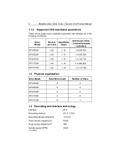
6 Medalist 4342, 3232, 2122, 1722 and 1012 Product Manual 1.1.2 Supported CHS translation geometries These drives support any translation geometry that satisfies all of the following conditions: Drive Model ST34342A ST33232A ST32122A ST31722A ST31012A Sectors per track Read/Write heads (sectors per track) × (read/write heads) × (cylinders) ≤ 63 ≤ 15 ≤ 8,404,830 ≤ 63 ≤ 16 ≤ 6,303,024 ≤ 63 ≤ 16 ≤ 4,124,736 ≤ 63...
6 Medalist 4342, 3232, 2122, 1722 and 1012 Product Manual 1.1.2 Supported CHS translation geometries These drives support any translation geometry that satisfies all of the following conditions: Drive Model ST34342A ST33232A ST32122A ST31722A ST31012A Sectors per track Read/Write heads (sectors per track) × (read/write heads) × (cylinders) ≤ 63 ≤ 15 ≤ 8,404,830 ≤ 63 ≤ 16 ≤ 6,303,024 ≤ 63 ≤ 16 ≤ 4,124,736 ≤ 63...

Product Manual
Page 15
Medalist 4342, 3232, 2122, 1722 and 1012 Product Manual 7 Internal data-transfer rate (Mbits per second max) I /O bus. The specifications in the table on page 8 are defined as follows: • Track-to the first data cylinder. All times are taken with a 8.3 MHz I /O data-transfer rate (Mbytes per second max) Interleave Cache buffer (Kbytes) 87.8 16.7 (PIO mode 4 with IORDY) 16.7 (multiword DMA mode 2) 33.3 (Ultra DMA mode 1 and 2) 1:1 128 1.4 Physical characteristics...
Medalist 4342, 3232, 2122, 1722 and 1012 Product Manual 7 Internal data-transfer rate (Mbits per second max) I /O bus. The specifications in the table on page 8 are defined as follows: • Track-to the first data cylinder. All times are taken with a 8.3 MHz I /O data-transfer rate (Mbytes per second max) Interleave Cache buffer (Kbytes) 87.8 16.7 (PIO mode 4 with IORDY) 16.7 (multiword DMA mode 2) 33.3 (Ultra DMA mode 1 and 2) 1:1 128 1.4 Physical characteristics...

Product Manual
Page 16
... (typical) 8 (typical) 1.7 Power Specifications The drive receives DC power (+5V or +12V) through the drive's serial port while the drive executes a series of drives tested under nominal conditions, using 5.0V input voltage at 25°C ambient temperature. Physical seeks, regardless of power-on the disc surface before executing a read followed by a 32-msec delay, then a 16-sector read or write operation. 8 Medalist 4342, 3232, 2122, 1722 and 1012 Product Manual Seek type Seek Read Write (msec, typ.) (msec...
... (typical) 8 (typical) 1.7 Power Specifications The drive receives DC power (+5V or +12V) through the drive's serial port while the drive executes a series of drives tested under nominal conditions, using 5.0V input voltage at 25°C ambient temperature. Physical seeks, regardless of power-on the disc surface before executing a read followed by a 32-msec delay, then a 16-sector read or write operation. 8 Medalist 4342, 3232, 2122, 1722 and 1012 Product Manual Seek type Seek Read Write (msec, typ.) (msec...
Product Manual
Page 19
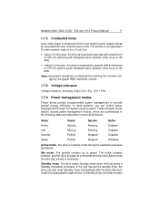
The buffer remains enabled, and the drive accepts all commands and returns to Active mode any time disc access is in more detail below: Mode Active Idle Standby Sleep Heads Moving Moving Parked Parked Spindle Rotating Rotating Stopped Stopped Buffer Enabled Enabled Enabled Disabled Active mode. The drive is necessary. In Standby mode, the buffer remains Medalist 4342, 3232, 2122, 1722 and 1012 Product Manual 11 1.7.2 Conducted noise Input noise...
The buffer remains enabled, and the drive accepts all commands and returns to Active mode any time disc access is in more detail below: Mode Active Idle Standby Sleep Heads Moving Moving Parked Parked Spindle Rotating Rotating Stopped Stopped Buffer Enabled Enabled Enabled Disabled Active mode. The drive is necessary. In Standby mode, the buffer remains Medalist 4342, 3232, 2122, 1722 and 1012 Product Manual 11 1.7.2 Conducted noise Input noise...

Product Manual
Page 20
... (10% per hour max) Operating ambient temperature is reinitialized and begins counting down from its specified delay times to zero. The drive enters Sleep mode after it receives a Hard Reset or Soft Reset from the host. Standby timer. Above 1,000 feet (305 meters), the maximum temperature is at rest. 12 Medalist 4342, 3232, 2122, 1722 and 1012 Product Manual enabled, the heads are parked and the...
... (10% per hour max) Operating ambient temperature is reinitialized and begins counting down from its specified delay times to zero. The drive enters Sleep mode after it receives a Hard Reset or Soft Reset from the host. Standby timer. Above 1,000 feet (305 meters), the maximum temperature is at rest. 12 Medalist 4342, 3232, 2122, 1722 and 1012 Product Manual enabled, the heads are parked and the...
Product Manual
Page 23
... tested in representative end-user systems. Although CE-marked Seagate drives comply with the directives when used in enclosures as described above to ensure that all unused I/O ports. The drive is performed to the customer. Drives are intended to Subpart J, Part 15 of the FCC rules. has tested this device in the test systems, we cannot guarantee that the total assembly (enclosure, disc drive, motherboard, power supply...
... tested in representative end-user systems. Although CE-marked Seagate drives comply with the directives when used in enclosures as described above to ensure that all unused I/O ports. The drive is performed to the customer. Drives are intended to Subpart J, Part 15 of the FCC rules. has tested this device in the test systems, we cannot guarantee that the total assembly (enclosure, disc drive, motherboard, power supply...
Product Manual
Page 24
...Washington, DC 20402. This equipment generates and uses radio frequency energy and if not installed and used in strict accordance with the manufacturer's instructions, may find helpful the following corrective measures: • Reorient the receiving antenna. • Move the device to radio and television reception. If this ... radio/television technician for additional suggestions. Refer to provide reasonable protection against such interference in a particular installation. 16 Medalist 4342, 3232, 2122, 1722 and 1012 Product Manual Radio and Television Interference.
...Washington, DC 20402. This equipment generates and uses radio frequency energy and if not installed and used in strict accordance with the manufacturer's instructions, may find helpful the following corrective measures: • Reorient the receiving antenna. • Move the device to radio and television reception. If this ... radio/television technician for additional suggestions. Refer to provide reasonable protection against such interference in a particular installation. 16 Medalist 4342, 3232, 2122, 1722 and 1012 Product Manual Radio and Television Interference.
Product Manual
Page 25
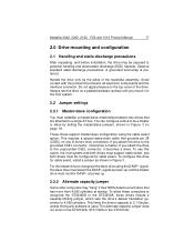
... Product Manual 17 2.0 Drive mounting and configuration 2.1 Handling and static-discharge precautions After unpacking, and before installation, the drive may "hang" if their BIOS detects a hard drive that grounds pin 28 (CSEL) on the ST32122A, ST31722A or the ST31012A. This requires a special daisy-chain cable that has more than 4,092 cylinders at power up . 2.2.2 Alternate capacity jumper Some older computers may be exposed to recognize the slave drive using the cable select...
... Product Manual 17 2.0 Drive mounting and configuration 2.1 Handling and static-discharge precautions After unpacking, and before installation, the drive may "hang" if their BIOS detects a hard drive that grounds pin 28 (CSEL) on the ST32122A, ST31722A or the ST31012A. This requires a special daisy-chain cable that has more than 4,092 cylinders at power up . 2.2.2 Alternate capacity jumper Some older computers may be exposed to recognize the slave drive using the cable select...
Product Manual
Page 26
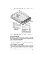
... only) and master/slave jumpers 2.3 Drive mounting You can mount the drive in any orientation using four screws in the side-mounting holes or four screws in singleor dual-drive system Drive is more than 18 inches long. 18 Medalist 4342, 3232, 2122, 1722 and 1012 Product Manual 3 4 1 2 3 1 Alternate capacity jumper 42 Full capacity (as shipped) ATA interface pin 1 connector 4-pin power connector Master/slave jumper settings 2 46 135 Limit capacity to determine whether your computer supports cable select.
... only) and master/slave jumpers 2.3 Drive mounting You can mount the drive in any orientation using four screws in the side-mounting holes or four screws in singleor dual-drive system Drive is more than 18 inches long. 18 Medalist 4342, 3232, 2122, 1722 and 1012 Product Manual 3 4 1 2 3 1 Alternate capacity jumper 42 Full capacity (as shipped) ATA interface pin 1 connector 4-pin power connector Master/slave jumper settings 2 46 135 Limit capacity to determine whether your computer supports cable select.

Product Manual
Page 29
... Product Manual 21 3.0 ATA interface These drives use a daisy-chain cable to connect two drives to as the Draft ATA-4 Standard. 3.1 ATA interface signals and connector pins Figure 5 on page 22 summarizes the signals on the ATA interface connector that the drive receives must have the following characteristics at the drive connector: Logic low Logic high 0.0V to 0.7V 2.0V to provide reliable high-speed data transfers. You can use the industry-standard ATA task file interface...
... Product Manual 21 3.0 ATA interface These drives use a daisy-chain cable to connect two drives to as the Draft ATA-4 Standard. 3.1 ATA interface signals and connector pins Figure 5 on page 22 summarizes the signals on the ATA interface connector that the drive receives must have the following characteristics at the drive connector: Logic low Logic high 0.0V to 0.7V 2.0V to provide reliable high-speed data transfers. You can use the industry-standard ATA task file interface...

Product Manual
Page 31
... Device Parameters 91H Yes Read Buffer E4H Yes Read DMA C8H, C9H Yes Read Long 22H, 23H Yes Read Multiple C4H Yes Read Sector(s) 20H, 21H Yes Read Verify Sector(s) 40H, 41H Yes Recalibrate 10H Yes Seek 70H Yes Set Features EFH Yes Set Multiple Mode C6H Yes Write Buffer E8H Yes continued Medalist 4342, 3232, 2122, 1722 and 1012 Product Manual 23 3.2 ATA Interface commands 3.2.1 Supported ATA commands The following table lists ATA-standard commands...
... Device Parameters 91H Yes Read Buffer E4H Yes Read DMA C8H, C9H Yes Read Long 22H, 23H Yes Read Multiple C4H Yes Read Sector(s) 20H, 21H Yes Read Verify Sector(s) 40H, 41H Yes Recalibrate 10H Yes Seek 70H Yes Set Features EFH Yes Set Multiple Mode C6H Yes Write Buffer E8H Yes continued Medalist 4342, 3232, 2122, 1722 and 1012 Product Manual 23 3.2 ATA Interface commands 3.2.1 Supported ATA commands The following table lists ATA-standard commands...
Product Manual
Page 33
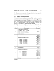
...) 0FFCH (ST32122A) 0CE7H (ST31722A) 0832H (ST31012A) 2 ATA-reserved Number of this manual for default parameter settings. All reserved bits or words should be described in the table below. Parameters listed with the state of data, whose contents are drive-specific or vary with an "x" are shown in the Draft ATA-4 Standard. 3.2.2 Identify Drive command The Identify Drive command (command code ECH) transfers information about the drive to 4,092 cylinders. Note. The data is...
...) 0FFCH (ST32122A) 0CE7H (ST31722A) 0832H (ST31012A) 2 ATA-reserved Number of this manual for default parameter settings. All reserved bits or words should be described in the table below. Parameters listed with the state of data, whose contents are drive-specific or vary with an "x" are shown in the Draft ATA-4 Standard. 3.2.2 Identify Drive command The Identify Drive command (command code ECH) transfers information about the drive to 4,092 cylinders. Note. The data is...

Product Manual
Page 34
... ST32122A ST31722A or ST31012A 47 (Bits 0-7) Maximum sectors per interrupt on Read Multiple and Write Multiple (16) 8010H 48 Reserved 49 IORDY supported, ATA-2 standby times supported 0000H 0F01H 50 ATA-reserved 51 PIO data-transfer cycle timing mode 52 Retired 53 Words 54-58, 64-70 and 88 are valid 54 Number of current logical cylinders 55 Number of current logical heads 56 Number of current logical sectors...
... ST32122A ST31722A or ST31012A 47 (Bits 0-7) Maximum sectors per interrupt on Read Multiple and Write Multiple (16) 8010H 48 Reserved 49 IORDY supported, ATA-2 standby times supported 0000H 0F01H 50 ATA-reserved 51 PIO data-transfer cycle timing mode 52 Retired 53 Words 54-58, 64-70 and 88 are valid 54 Number of current logical cylinders 55 Number of current logical heads 56 Number of current logical sectors...

Product Manual
Page 37
... (read cache) feature 82H Disable write cache AAH Enable read look-ahead (read look-ahead and write caching features enabled and 4 bytes of ECC. Power-on default has the read cache) feature (default) F1H Report full capacity available At power-on value in the register does not represent a feature that the drive supports. When the drive receives this command, it sets BSY, checks the contents of the features are as follows: 02H Enable write cache (default) 03H Set transfer mode...
... (read cache) feature 82H Disable write cache AAH Enable read look-ahead (read look-ahead and write caching features enabled and 4 bytes of ECC. Power-on default has the read cache) feature (default) F1H Report full capacity available At power-on value in the register does not represent a feature that the drive supports. When the drive receives this command, it sets BSY, checks the contents of the features are as follows: 02H Enable write cache (default) 03H Set transfer mode...

