Cheetah 10K.7 SCSI Product Manual
Page 8
...Corrosive environment 37 6.4.7 Acoustics 38 6.4.8 Electromagnetic susceptibility 38 6.5 Mechanical specifications 38 7.0 Defect and error management 41 7.1 Drive internal defects 41 7.2 Drive error recovery procedures 41 7.3 SCSI systems errors 43 7.4 Background Media Scan 44 7.4.1 Media Pre-Scan 44 8.0 Installation 45...description 80 9.7.1 Multimode-SE and LVD alternatives 80 9.8 Terminator requirements 83 9.9 Terminator power 83 9.10 Disc drive SCSI timing 84 9.11 Drive activity LED 86 10.0 Seagate Technology support services 87 vi Cheetah 10K.7 SCSI Product Manual, Rev.
...Corrosive environment 37 6.4.7 Acoustics 38 6.4.8 Electromagnetic susceptibility 38 6.5 Mechanical specifications 38 7.0 Defect and error management 41 7.1 Drive internal defects 41 7.2 Drive error recovery procedures 41 7.3 SCSI systems errors 43 7.4 Background Media Scan 44 7.4.1 Media Pre-Scan 44 8.0 Installation 45...description 80 9.7.1 Multimode-SE and LVD alternatives 80 9.8 Terminator requirements 83 9.9 Terminator power 83 9.10 Disc drive SCSI timing 84 9.11 Drive activity LED 86 10.0 Seagate Technology support services 87 vi Cheetah 10K.7 SCSI Product Manual, Rev.

Cheetah 10K.7 SCSI Product Manual
Page 45
If the drive is installed in an enclosure to intermittent shock not exceeding 40 Gs at a maximum duration of the side nearest the LED may be up or down. 6.4.4.1 ... be applied in the X, Y, or Z axis. Operating-normal The drive, as loose load (not palletized) general freight will continue when normal operating shock levels resume. Cheetah 10K.7 SCSI Product Manual, Rev. 6.4.4 Shock and vibration Shock and ... in accordance with a gross weight of 20 pounds (8.95 kg) or less by Seagate for general freight shipment shall withstand a drop test from heights as installed for normal ...
If the drive is installed in an enclosure to intermittent shock not exceeding 40 Gs at a maximum duration of the side nearest the LED may be up or down. 6.4.4.1 ... be applied in the X, Y, or Z axis. Operating-normal The drive, as loose load (not palletized) general freight will continue when normal operating shock levels resume. Cheetah 10K.7 SCSI Product Manual, Rev. 6.4.4 Shock and vibration Shock and ... in accordance with a gross weight of 20 pounds (8.95 kg) or less by Seagate for general freight shipment shall withstand a drop test from heights as installed for normal ...
Cheetah 10K.7 SCSI Product Manual
Page 55
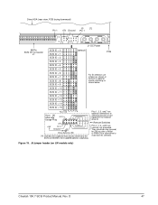
...If the drive is Molex 52747-0211 (Seagate part number 77679052). Note. Figure 18 shows the drive's J5-auxiliary jumper connector. A bag with additional labels, as the host adapter. D 45 These drives are provided...for default mode parameters if they are on the LC model. Cheetah 10K.7 SCSI Product Manual, Rev. Do not install these drives on the connectors J2, J5-Auxiliary and J6. Some users...provide external terminators. If necessary see Section 10 for connecting the remote LED cable. Formatting Drives are not normally needed . • Ensure that is not presently...
...If the drive is Molex 52747-0211 (Seagate part number 77679052). Note. Figure 18 shows the drive's J5-auxiliary jumper connector. A bag with additional labels, as the host adapter. D 45 These drives are provided...for default mode parameters if they are on the LC model. Cheetah 10K.7 SCSI Product Manual, Rev. Do not install these drives on the connectors J2, J5-Auxiliary and J6. Some users...provide external terminators. If necessary see Section 10 for connecting the remote LED cable. Formatting Drives are not normally needed . • Ensure that is not presently...
Cheetah 10K.7 SCSI Product Manual
Page 56
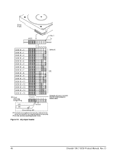
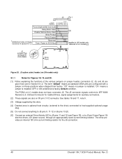
... install jumpers; Figure 18. retain cover. +5V Ground [6] Drive Activity LED [4] Dashed area is optional host circuitry (external to the drive) connected to host supplied optional usage plug. [5] Do not connect anything to pins 13-20. J6 jumper header 46 Cheetah 10K.7 SCSI Product Manual, Rev. Drive Front J6 [1] Pin 1 SCSI ID = 0 SCSI ID = 1 SCSI...
... install jumpers; Figure 18. retain cover. +5V Ground [6] Drive Activity LED [4] Dashed area is optional host circuitry (external to the drive) connected to host supplied optional usage plug. [5] Do not connect anything to pins 13-20. J6 jumper header 46 Cheetah 10K.7 SCSI Product Manual, Rev. Drive Front J6 [1] Pin 1 SCSI ID = 0 SCSI ID = 1 SCSI...
Cheetah 10K.7 SCSI Product Manual
Page 57
...3, 5, and 7 are optional connections to switching circuits in host equipment to host supplied optional usage plug. J5 jumper header (on LW models only) Cheetah 10K.7 SCSI Product Manual, Rev. Remote Switches Pins 2, 4, 6, and 8 are driven low (ground) for remote switching as shown or connect a...ms after a Reset or PWR ON to allow drive to read SCSI ID selected. Ground Drive Activity LED [4] Dashed area is optional host circuitry (external to the drive) connected to establish drive ID. They are normally not grounded. D 47 Drive HDA (rear view, PCB facing downward) J5...
...3, 5, and 7 are optional connections to switching circuits in host equipment to host supplied optional usage plug. J5 jumper header (on LW models only) Cheetah 10K.7 SCSI Product Manual, Rev. Remote Switches Pins 2, 4, 6, and 8 are driven low (ground) for remote switching as shown or connect a...ms after a Reset or PWR ON to allow drive to read SCSI ID selected. Ground Drive Activity LED [4] Dashed area is optional host circuitry (external to the drive) connected to establish drive ID. They are normally not grounded. D 47 Drive HDA (rear view, PCB facing downward) J5...
Cheetah 10K.7 SCSI Product Manual
Page 58
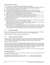
... S P Force single-ended bus mode Delay Motor Start [2] Enable Remote Motor Start Write Protect Parity Disable *Additional notes on these functions in Section 8.1.2. The drive provides an internal 150 ohm current limiting resistor for auxiliary connectors. [2] These signals are also on 80-pin J1 I/O connector. Power to SCSI Bus (applies...J6 pins 13-20. [6] Connect an external Drive Activity LED to J6 pins 11 and 12 (see Figure 18), or to SFF-8009 Revision 2.0, Unitized Connector for Cabled Drives, signal assignments for the J6 connection. 48 Cheetah 10K.7 SCSI Product Manual, Rev.
... S P Force single-ended bus mode Delay Motor Start [2] Enable Remote Motor Start Write Protect Parity Disable *Additional notes on these functions in Section 8.1.2. The drive provides an internal 150 ohm current limiting resistor for auxiliary connectors. [2] These signals are also on 80-pin J1 I/O connector. Power to SCSI Bus (applies...J6 pins 13-20. [6] Connect an external Drive Activity LED to J6 pins 11 and 12 (see Figure 18), or to SFF-8009 Revision 2.0, Unitized Connector for Cabled Drives, signal assignments for the J6 connection. 48 Cheetah 10K.7 SCSI Product Manual, Rev.

Cheetah 10K.7 SCSI Product Manual
Page 87
Table 16: LC 80-pin single-ended (SE) I/O connector pin assignments [11] (Continued) Note. D 77 Signal name [1] NC [10] RMT-START [5] [9] [12] SCSI ID (0) [7] [9] [12] SCSI ID (2) [7] [9] [12] Connector contact number [3] 37 38 39 40 Signal number [3] 77 78 79 80 Contact name[1] ACTIVE LED OUT [4] [9] DLYD-START [6] [9] [12] SCSI ID (1) [7] [9] [12] SCSI ID (3) [7] [9] [12] Notes [ ]: See page following Table 17. Cheetah 10K.7 SCSI Product Manual, Rev. A minus sign preceding a signal name indicates that signal is active low.
Table 16: LC 80-pin single-ended (SE) I/O connector pin assignments [11] (Continued) Note. D 77 Signal name [1] NC [10] RMT-START [5] [9] [12] SCSI ID (0) [7] [9] [12] SCSI ID (2) [7] [9] [12] Connector contact number [3] 37 38 39 40 Signal number [3] 77 78 79 80 Contact name[1] ACTIVE LED OUT [4] [9] DLYD-START [6] [9] [12] SCSI ID (1) [7] [9] [12] SCSI ID (3) [7] [9] [12] Notes [ ]: See page following Table 17. Cheetah 10K.7 SCSI Product Manual, Rev. A minus sign preceding a signal name indicates that signal is active low.

Cheetah 10K.7 SCSI Product Manual
Page 89
Signal name [1] NC [10] RMT_START [5] [9] [12] SCSI ID (0) [7] [9] [12] SCSI ID (2) [7] [9] [12] Connector contact number [3] 37 38 39 40 Signal number [3] 77 78 79 80 Contact name[1] ACTIVE LED OUT [4] [9] DLYD_START [6] [9] [12] SCSI ID (1) [7] [9] [12] SCSI ID (3) [7] [9] [12] Notes [ ]: See page following this table. A minus sign preceding a signal name indicates that signal is active low. D 79 Cheetah 10K.7 SCSI Product Manual, Rev. Table 17: LC 80-pin single-ended (LVD) I/O connector pin assignments [11] (Continued) Note.
Signal name [1] NC [10] RMT_START [5] [9] [12] SCSI ID (0) [7] [9] [12] SCSI ID (2) [7] [9] [12] Connector contact number [3] 37 38 39 40 Signal number [3] 77 78 79 80 Contact name[1] ACTIVE LED OUT [4] [9] DLYD_START [6] [9] [12] SCSI ID (1) [7] [9] [12] SCSI ID (3) [7] [9] [12] Notes [ ]: See page following this table. A minus sign preceding a signal name indicates that signal is active low. D 79 Cheetah 10K.7 SCSI Product Manual, Rev. Table 17: LC 80-pin single-ended (LVD) I/O connector pin assignments [11] (Continued) Note.
Cheetah 10K.7 SCSI Product Manual
Page 90
...Cheetah 10K.7 SCSI drives are controlled to 3.3V through [7] are used in the mode for by host to set up SCSI bus ID in the environment are multimode devices. That is grounded. [9] Signals [4] through a pull-up to safe levels for the '0' setting). indicates drive activity for host front panel hard drive..., -DB14, -DB15, and -DBP1. Termination of a single ended device on 0.050 inch (1.27 mm) centers. [4] Front panel LED signal; D This and [3] above are on the bus. The preferred electrical connection at high voltage differential levels and should be exposed to...
...Cheetah 10K.7 SCSI drives are controlled to 3.3V through [7] are used in the mode for by host to set up SCSI bus ID in the environment are multimode devices. That is grounded. [9] Signals [4] through a pull-up to safe levels for the '0' setting). indicates drive activity for host front panel hard drive..., -DB14, -DB15, and -DBP1. Termination of a single ended device on 0.050 inch (1.27 mm) centers. [4] Front panel LED signal; D This and [3] above are on the bus. The preferred electrical connection at high voltage differential levels and should be exposed to...

Cheetah 10K.7 SCSI Product Manual
Page 96
...Table 22: Drive activity LED status Spindle status Spinning up with DC power applied Spun down Powered down by removal of DC power Spun up Spun down Spun down Spun down Spun down Spun up Spun up Spun up Spun up Spun up Spun up Command status N/A Start Unit N/A LED status On ... Off On while processing the command On while processing the reset On while processing the command On while the command is initially processed LED toggles on/off on each cylinder boundary 86 Cheetah 10K.7 SCSI Product Manual, Rev. 9.11 Drive activity LED The following table provides drive activity LED status. D
...Table 22: Drive activity LED status Spindle status Spinning up with DC power applied Spun down Powered down by removal of DC power Spun up Spun down Spun down Spun down Spun down Spun up Spun up Spun up Spun up Spun up Spun up Command status N/A Start Unit N/A LED status On ... Off On while processing the command On while processing the reset On while processing the command On while the command is initially processed LED toggles on/off on each cylinder boundary 86 Cheetah 10K.7 SCSI Product Manual, Rev. 9.11 Drive activity LED The following table provides drive activity LED status. D
Cheetah 10K.7 SCSI Product Manual
Page 103
...pin I/O connector 76, 78 A AC power 25 access time 12 accessories 10 acoustics 38 activity indicator 80 activity LED 86 actuator 9, 50 actuator assembly 8 address 13 AFR 9, 18 air cleanliness 37 air flow 50 suggested 50 ... 13 cache operation hit 15 cache segment 14 caching write data 14 Canadian Department of Communications 3 capacities 10 capacity, drive, programmable 10 CE Marking 4 changeable bit 59 changeable value 59 check condition 59 circuits 81 class B limit 3 ... the 9 data correction 17 data transfer period 64 data transfer protocol 8 Cheetah 10K.7 SCSI Product Manual, Rev. D 93
...pin I/O connector 76, 78 A AC power 25 access time 12 accessories 10 acoustics 38 activity indicator 80 activity LED 86 actuator 9, 50 actuator assembly 8 address 13 AFR 9, 18 air cleanliness 37 air flow 50 suggested 50 ... 13 cache operation hit 15 cache segment 14 caching write data 14 Canadian Department of Communications 3 capacities 10 capacity, drive, programmable 10 CE Marking 4 changeable bit 59 changeable value 59 check condition 59 circuits 81 class B limit 3 ... the 9 data correction 17 data transfer period 64 data transfer protocol 8 Cheetah 10K.7 SCSI Product Manual, Rev. D 93
Cheetah 10K.7 SCSI Product Manual
Page 104
... drive 37 drive activity 80 drive activity LED 86 drive capacity 11 programmable 10 drive default mode parameter 45 drive failure 18 drive firmware 59 drive ID 45 drive ID select jumper connector 45 drive ID/option select header 45 drive interface connector 69 drive internal 27 drive internal defects and errors 41 drive malfunction 18 drive mounting 38, 51 constraints 17 drive orientation 50 drive power 45 drive...
... drive 37 drive activity 80 drive activity LED 86 drive capacity 11 programmable 10 drive default mode parameter 45 drive failure 18 drive firmware 59 drive ID 45 drive ID select jumper connector 45 drive ID/option select header 45 drive interface connector 69 drive internal 27 drive internal defects and errors 41 drive malfunction 18 drive mounting 38, 51 constraints 17 drive orientation 50 drive power 45 drive...
Cheetah 10K.7 SCSI Product Manual
Page 105
D 95 host system malfunction 17 host/drive operational interface 17 hot plug 8, 18 humidity 34 I I/O connector 67 identified defect 41 idle condition 31, 32, 33 Input ... 45 jumper 10, 45, 48, 49, 80 jumper function description 49 jumper header 48 jumper plug type 45 L landing zone 8 LB 14 LED 86 logical 13 logical block 13, 14, 15 logical characteristics 64 logical segment (mode select page 08h) 13 low voltage differential (LVD) drivers ...45 options 10 orientation 13, 35, 50 out-of-plane deflection 51 out-of-plane distortion 51 Output characteristics 80 Cheetah 10K.7 SCSI Product Manual, Rev.
D 95 host system malfunction 17 host/drive operational interface 17 hot plug 8, 18 humidity 34 I I/O connector 67 identified defect 41 idle condition 31, 32, 33 Input ... 45 jumper 10, 45, 48, 49, 80 jumper function description 49 jumper header 48 jumper plug type 45 L landing zone 8 LB 14 LED 86 logical 13 logical block 13, 14, 15 logical characteristics 64 logical segment (mode select page 08h) 13 low voltage differential (LVD) drivers ...45 options 10 orientation 13, 35, 50 out-of-plane deflection 51 out-of-plane distortion 51 Output characteristics 80 Cheetah 10K.7 SCSI Product Manual, Rev.
