
Product Manual
Page 9
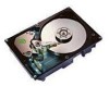
...vii Figure 1. Figure 3. Figure 4a. Figure 6. Figure 12. Figure 17. Figure 18. List of Figures Barracuda 9 disc drive (ST19171N drive shown 1 Barracuda 9 family drive 6 Typical Barracuda 9 drive +5 V and +12 V current profile 23 Location of PCB components listed in Table 3 25 Location of ..." models 32 ST19171N option select jumper connectors 36 ST19171W/WD option select jumper connectors 37 ST19171WC/DC option select jumper connectors 38 Suggested air flow 41 Physical interface for "N" model drives 53 Physical interface for "W" and "WD" model drives (68-pin J1 SCSI I/O connector...
...vii Figure 1. Figure 3. Figure 4a. Figure 6. Figure 12. Figure 17. Figure 18. List of Figures Barracuda 9 disc drive (ST19171N drive shown 1 Barracuda 9 family drive 6 Typical Barracuda 9 drive +5 V and +12 V current profile 23 Location of PCB components listed in Table 3 25 Location of ..." models 32 ST19171N option select jumper connectors 36 ST19171W/WD option select jumper connectors 37 ST19171WC/DC option select jumper connectors 38 Suggested air flow 41 Physical interface for "N" model drives 53 Physical interface for "W" and "WD" model drives (68-pin J1 SCSI I/O connector...
Product Manual
Page 16
..., or top-down mounting • Dynamic spindle brake • Active IC terminators enabled by jumper ("N" and "W" models only) • 512 Kbyte data buffer (2 Mbyte data buffer available as an option). 6 Barracuda 9 Product Manual, Rev. Barracuda 9 family drive 3.1 Standard features Barracuda 9 drives have the following standard features: • Integrated SCSI controller • Single-ended or differential SCSI...
..., or top-down mounting • Dynamic spindle brake • Active IC terminators enabled by jumper ("N" and "W" models only) • 512 Kbyte data buffer (2 Mbyte data buffer available as an option). 6 Barracuda 9 Product Manual, Rev. Barracuda 9 family drive 3.1 Standard features Barracuda 9 drives have the following standard features: • Integrated SCSI controller • Single-ended or differential SCSI...

Product Manual
Page 17
... otherwise specified). A value greater than the maximum number of LBAs changes the total drive capacity to the maximum capacity. 3.7 Factory installed accessories The Barracuda 9 Installation Guide, part number 83329020, is rounded down to the value in the number of blocks field. average latency = 4.17 ...13 in the SCSI Interface Product Manual, part number 77738479. [2] The number of data tracks per sparing zone and the number of jumpers are formatted to configure the option headers (J2 and J6). See Mode Select Command and Format Command in the SCSI Interface Product Manual,...
... otherwise specified). A value greater than the maximum number of LBAs changes the total drive capacity to the maximum capacity. 3.7 Factory installed accessories The Barracuda 9 Installation Guide, part number 83329020, is rounded down to the value in the number of blocks field. average latency = 4.17 ...13 in the SCSI Interface Product Manual, part number 77738479. [2] The number of data tracks per sparing zone and the number of jumpers are formatted to configure the option headers (J2 and J6). See Mode Select Command and Format Command in the SCSI Interface Product Manual,...
Product Manual
Page 27
...standard. 3. will reset the timer so that indicate a drive failure and is enabled. C 17 5.2.6 Hot plugging Barracuda 9 disc drives Caution: Hot-plug drives are optimized to be interrogated by a log sense command to the bus. Barracuda 9 drives conform to allow data back-up and power-down periods... 1, 2, 3, and 4. 2. Ensure that all jumpers from the bus. Insert or remove the drive after connecting the device to log page 0x3E. Configure the drive with the bus connector. Ensure that conform to the drive you are inserting or removing). Each attribute has been...
...standard. 3. will reset the timer so that indicate a drive failure and is enabled. C 17 5.2.6 Hot plugging Barracuda 9 disc drives Caution: Hot-plug drives are optimized to be interrogated by a log sense command to the bus. Barracuda 9 drives conform to allow data back-up and power-down periods... 1, 2, 3, and 4. 2. Ensure that all jumpers from the bus. Insert or remove the drive after connecting the device to log page 0x3E. Configure the drive with the bus connector. Ensure that conform to the drive you are inserting or removing). Each attribute has been...

Product Manual
Page 45
...sector allocation scheme is not provided by host system documentation or with the standard OEM drives. Suggested part number for installation. Barracuda 9 Product Manual, Rev. Configure drive options For option jumper locations and definitions refer to make the new settings effective. • Installation instructions ... the drive for the system into which the drive is Molex 52747-0211(Seagate P/N 70935865). The drive is shipped from the drive and do not need to set the drive ID using jumper plug TE if termination is selected. • High level format the drive involves...
...sector allocation scheme is not provided by host system documentation or with the standard OEM drives. Suggested part number for installation. Barracuda 9 Product Manual, Rev. Configure drive options For option jumper locations and definitions refer to make the new settings effective. • Installation instructions ... the drive for the system into which the drive is Molex 52747-0211(Seagate P/N 70935865). The drive is shipped from the drive and do not need to set the drive ID using jumper plug TE if termination is selected. • High level format the drive involves...

Product Manual
Page 46
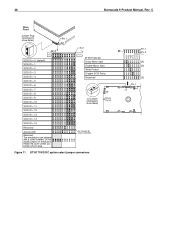
... Motor Start Enable Motor Start Write Protect Disable SCSI Parity Reserved [3] Pin 1 Term. ST19171N option select jumper connectors Power from SCSI Bus (position A) Term. Do not install jumpers on these pins. Power from Drive (default) Term. 36 Barracuda 9 Product Manual, Rev. Retain the cover unless you install a 20-pin plug. +5V (anode) [6] -Active (cathode...
... Motor Start Enable Motor Start Write Protect Disable SCSI Parity Reserved [3] Pin 1 Term. ST19171N option select jumper connectors Power from SCSI Bus (position A) Term. Do not install jumpers on these pins. Power from Drive (default) Term. 36 Barracuda 9 Product Manual, Rev. Retain the cover unless you install a 20-pin plug. +5V (anode) [6] -Active (cathode...
Product Manual
Page 47
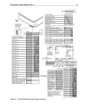
... Enable Motor Start Write Protect Disable SCSI Parity Reserved Pin 1 J2 Pin 2 RT T T D MW P E P P ESEPDS2 1 [3] Pin 1 ST19171W Enable Terminator (default) Term. Power to external terminator. power to SCSI Bus and Drive ST19171WD Term. Pin 1 J2 Jumper (enlarged to show detail) J6 [4] SCSI ID = 0 (default) SCSI ID = 1 SCSI ID = 2 SCSI ID = 3 SCSI ID = 4 SCSI... ID = 7 SCSI ID = 8 SCSI ID = 9 SCSI ID = 10 SCSI ID = 11 SCSI ID = 12 SCSI ID = 13 SCSI ID = 14 SCSI ID = 15 Figure 10. Barracuda 9 Product Manual, Rev.
... Enable Motor Start Write Protect Disable SCSI Parity Reserved Pin 1 J2 Pin 2 RT T T D MW P E P P ESEPDS2 1 [3] Pin 1 ST19171W Enable Terminator (default) Term. Power to external terminator. power to SCSI Bus and Drive ST19171WD Term. Pin 1 J2 Jumper (enlarged to show detail) J6 [4] SCSI ID = 0 (default) SCSI ID = 1 SCSI ID = 2 SCSI ID = 3 SCSI ID = 4 SCSI... ID = 7 SCSI ID = 8 SCSI ID = 9 SCSI ID = 10 SCSI ID = 11 SCSI ID = 12 SCSI ID = 13 SCSI ID = 14 SCSI ID = 15 Figure 10. Barracuda 9 Product Manual, Rev.
Product Manual
Page 48
... install a 20-pin plug. ST19171WC/DC Delay Motor Start Enable Motor Start Write Protect Disable SCSI Parity Reserved J2 Jumper (enlarged to show detail) J6 Drive Front +5V (anode) [6] -Active (cathode) Figure 11. C Drive Front Jumper Plug (enlarged to show detail) Pin 1 J6 [4] Pin 1 SCSI ID = 0 (default) SCSI ID = 1 SCSI ... SCSI ID = 15 Reserved Activity LED Reserved The shaded pins are shipped with a cover installed. ST19171WC/DC option select jumper connectors Pin 1 J2 Pin 2 R RR R E D MW P E E E SSEPDSS S [5] [5] [3] Pin 1 J2 38 Barracuda 9 Product Manual, Rev.
... install a 20-pin plug. ST19171WC/DC Delay Motor Start Enable Motor Start Write Protect Disable SCSI Parity Reserved J2 Jumper (enlarged to show detail) J6 Drive Front +5V (anode) [6] -Active (cathode) Figure 11. C Drive Front Jumper Plug (enlarged to show detail) Pin 1 J6 [4] Pin 1 SCSI ID = 0 (default) SCSI ID = 1 SCSI ... SCSI ID = 15 Reserved Activity LED Reserved The shaded pins are shipped with a cover installed. ST19171WC/DC option select jumper connectors Pin 1 J2 Pin 2 R RR R E D MW P E E E SSEPDSS S [5] [5] [3] Pin 1 J2 38 Barracuda 9 Product Manual, Rev.

Product Manual
Page 49
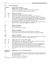
...Figure 9 9 9 10 [a] 10 [a] 10 11 [d] 11 [d] 11 11 11 11 ("X" means the function selection can be made with a jumper on "N," "WC," and "DC" model drives does not have connector J1-Auxiliary. See pinout Table 16 and 17. [c] The host can be used on J1. The term "default" means... as standard OEM units are configured with jumpers on the different Barracuda 9 model drives. [5] These signals are given here and in Section 8.1.2. Jumper plugs can drive a remotely located Drive Activity LED using signal. [d] Use either J6 or J1-Aux, but not both ....
...Figure 9 9 9 10 [a] 10 [a] 10 11 [d] 11 [d] 11 11 11 11 ("X" means the function selection can be made with a jumper on "N," "WC," and "DC" model drives does not have connector J1-Auxiliary. See pinout Table 16 and 17. [c] The host can be used on J1. The term "default" means... as standard OEM units are configured with jumpers on the different Barracuda 9 model drives. [5] These signals are given here and in Section 8.1.2. Jumper plugs can drive a remotely located Drive Activity LED using signal. [d] Use either J6 or J1-Aux, but not both ....
Product Manual
Page 50
...) terminator circuits are enabled. (Default) On-board (non-removable) terminator circuits are disabled. 40 Barracuda 9 Product Manual, Rev. C 8.1.2 Function description J2 Jumpers TE On Off Jumper Function Description (Applies only to the drive's internal terminators (for spindle sync cabling. Off Drive checks for parity and reports the results of 2 starts after power up. (Default) Spindle...
...) terminator circuits are enabled. (Default) On-board (non-removable) terminator circuits are disabled. 40 Barracuda 9 Product Manual, Rev. C 8.1.2 Function description J2 Jumpers TE On Off Jumper Function Description (Applies only to the drive's internal terminators (for spindle sync cabling. Off Drive checks for parity and reports the results of 2 starts after power up. (Default) Spindle...

Product Manual
Page 54
... error counter page (05h) Write error counter page (02h) Command Code 40h 39h 18h 3Ah 04h 12h 36h 4Ch 4Dh Supported by Barracuda 9 family drive Command Name Change definition Compare Copy Copy and verify Format unit [1] Block format Bytes from index Physical sector format DPRY bit supported DCRT ...VS (vendor specific) bit Inquiry Date code page (C1h) Device behavior page (C3h) Firmware numbers page (C0h) Implemented operating definitions page (81h) Jumper settings page (C2h) Supported vital product data pages (0h) Unit serial number page (80h) Lock-unlock cache Log select DU bit DS bit TSD...
... error counter page (05h) Write error counter page (02h) Command Code 40h 39h 18h 3Ah 04h 12h 36h 4Ch 4Dh Supported by Barracuda 9 family drive Command Name Change definition Compare Copy Copy and verify Format unit [1] Block format Bytes from index Physical sector format DPRY bit supported DCRT ...VS (vendor specific) bit Inquiry Date code page (C1h) Device behavior page (C3h) Firmware numbers page (C0h) Implemented operating definitions page (81h) Jumper settings page (C2h) Supported vital product data pages (0h) Unit serial number page (80h) Lock-unlock cache Log select DU bit DS bit TSD...
Product Manual
Page 65
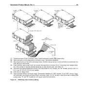
...must be used . Both ends of loads, transfer rates, and cost to minimize noise effects. The drive may require trade-offs in the same bus. Remove the terminator enable jumper TE on the same daisy chain with SCSI devices having the same type drivers and receivers. To ...at both ends of 8 ("N" models) or 16 ("W" and "WC") SCSI devices (including the host) may be terminated. "N" models use non-shielded cable connectors. Barracuda 9 Product Manual, Rev. A maximum of the daisy chain are : Flat cable - 35M-3365-68 Twisted pair - However, please note the restrictions described in ...
...must be used . Both ends of loads, transfer rates, and cost to minimize noise effects. The drive may require trade-offs in the same bus. Remove the terminator enable jumper TE on the same daisy chain with SCSI devices having the same type drivers and receivers. To ...at both ends of 8 ("N" models) or 16 ("W" and "WC") SCSI devices (including the host) may be terminated. "N" models use non-shielded cable connectors. Barracuda 9 Product Manual, Rev. A maximum of the daisy chain are : Flat cable - 35M-3365-68 Twisted pair - However, please note the restrictions described in ...
Product Manual
Page 69
Install terminator enable (TE) jumper plug. [2] Open-end type (in Section 9.6.3.1 (including host adapter/initia- "N" ... "W" models, priority is ID 7 to ID 0, then ID 15 to ID 8 (ID 8 very lowest). [6] Last drive on the end of devices allowed depends on the end with the terminator, the host having no terminator. [4] Total interface cable... length must not exceed that specified in -line application) connector used . Barracuda 9 Product Manual, Rev. If end "WD" device, exter- nal terminator and closed-end type 68-pin connector used...
Install terminator enable (TE) jumper plug. [2] Open-end type (in Section 9.6.3.1 (including host adapter/initia- "N" ... "W" models, priority is ID 7 to ID 0, then ID 15 to ID 8 (ID 8 very lowest). [6] Last drive on the end of devices allowed depends on the end with the terminator, the host having no terminator. [4] Total interface cable... length must not exceed that specified in -line application) connector used . Barracuda 9 Product Manual, Rev. If end "WD" device, exter- nal terminator and closed-end type 68-pin connector used...
Product Manual
Page 78
... assignments. [3] Connector contacts are connected to the conductor position when using 0.050 inch (1.27 mm) centerline flat ribbon cable. indicates drive activity for Tables 13 through [7] are used to enable Delayed Motor Start option (motor starts at power on 0.100 inch (2.54 ...hard drive activity indicator. [5] Asserted by host to left in place of 12 seconds multiplied by host to implement equivalent contact assignments. [12] Connector contacts are on or after a delay of installing jumpers and cables on 0.050 inch (1.27 mm) centers. [4] Front panel LED signal; 68 Barracuda ...
... assignments. [3] Connector contacts are connected to the conductor position when using 0.050 inch (1.27 mm) centerline flat ribbon cable. indicates drive activity for Tables 13 through [7] are used to enable Delayed Motor Start option (motor starts at power on 0.100 inch (2.54 ...hard drive activity indicator. [5] Asserted by host to left in place of 12 seconds multiplied by host to implement equivalent contact assignments. [12] Connector contacts are on or after a delay of installing jumpers and cables on 0.050 inch (1.27 mm) centers. [4] Front panel LED signal; 68 Barracuda ...
Product Manual
Page 79
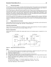
...transmitters and receivers Notes. [1] Part of 0.4 volt. C 69 9.7 Electrical description ST19171N and ST19171W models use an ANSI SCSI compatible open collector or three state drivers. These drives have no provisions for "N," "W," and "WC" models are defined as a line receiver. Transmitter...be provided by the user. Receiver characteristics Single-ended drives use differential interface signals and each differential pair. Barracuda 9 Product Manual, Rev. ST19171WD models use an ANSI SCSI single-ended receiver with jumper plug TE when it is required. 9.7.1 Single-...
...transmitters and receivers Notes. [1] Part of 0.4 volt. C 69 9.7 Electrical description ST19171N and ST19171W models use an ANSI SCSI compatible open collector or three state drivers. These drives have no provisions for "N," "W," and "WC" models are defined as a line receiver. Transmitter...be provided by the user. Receiver characteristics Single-ended drives use differential interface signals and each differential pair. Barracuda 9 Product Manual, Rev. ST19171WD models use an ANSI SCSI single-ended receiver with jumper plug TE when it is required. 9.7.1 Single-...
Product Manual
Page 81
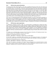
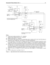
See Section 9.7.2 for powering external terminators if the drive option select header jumper TP (Figures 9 and 10) is installed in rightmost position "TP." Figure 21. See Tables 15 and 17. Typical differential I /O cable ground. C 71 +5V...is made by user, systems integrator, or host equipment manufacturer where needed. Barracuda 9 Product Manual, Rev. See pin assignment Tables 15 and 17 for connecting terminator power to end of I /O line terminators. As a help, drive +5 V power is a Seagate disc drive, terminators and a place to plug them in must be provided external to...
See Section 9.7.2 for powering external terminators if the drive option select header jumper TP (Figures 9 and 10) is installed in rightmost position "TP." Figure 21. See Tables 15 and 17. Typical differential I /O cable ground. C 71 +5V...is made by user, systems integrator, or host equipment manufacturer where needed. Barracuda 9 Product Manual, Rev. See pin assignment Tables 15 and 17 for connecting terminator power to end of I /O line terminators. As a help, drive +5 V power is a Seagate disc drive, terminators and a place to plug them in must be provided external to...
Product Manual
Page 82
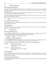
... source drive capability 3.0 A maximum ST19171WD drives You can configure terminator power in four different ways. ST19171WC and ST19171DC drives SCA connector drives do not have internal terminators available. 72 Barracuda 9 Product Manual, Rev. C 9.8 Terminator requirements ST19171N and ST19171W drives Internal disc drive I/O... the initiator and drive. Remove the Enable SCSI Terminator jumper from the drive to terminator power. Drive accepts terminator power through SCSI bus pins: ST19171N Pin 26 ST19171W Pins 17, 18, 51, and 52 2. Drive provides power to its...
... source drive capability 3.0 A maximum ST19171WD drives You can configure terminator power in four different ways. ST19171WC and ST19171DC drives SCA connector drives do not have internal terminators available. 72 Barracuda 9 Product Manual, Rev. C 9.8 Terminator requirements ST19171N and ST19171W drives Internal disc drive I/O... the initiator and drive. Remove the Enable SCSI Terminator jumper from the drive to terminator power. Drive accepts terminator power through SCSI bus pins: ST19171N Pin 26 ST19171W Pins 17, 18, 51, and 52 2. Drive provides power to its...

Product Manual
Page 85
..., free utility programs, drive specifications and jumper settings for disc drives and tape drives. Responses are familiar with system conflicts and other Seagate products, use a touch-tone telephone to access Seagate's automated FAX system to that contains information about Seagate products over the Internet from Seagate's World Wide Web home page (http://www.seagate.com) or Seagate's ftp server (ftp...
..., free utility programs, drive specifications and jumper settings for disc drives and tape drives. Responses are familiar with system conflicts and other Seagate products, use a touch-tone telephone to access Seagate's automated FAX system to that contains information about Seagate products over the Internet from Seagate's World Wide Web home page (http://www.seagate.com) or Seagate's ftp server (ftp...

Product Manual
Page 88
... drive ID 35, 39 drive ID select jumper connector 35 drive internal defects and errors 33 drive mounting 42 drive orientation 41 drive power 35 drive primary defects list 33 drive reset 39 drive select headers 52 drive volume 35 drivers/receivers 6 differential 70 single-ended 69 DS bit command 44 DSP bit 44 DU bit 44 E EFT defect list 33 Barracuda...
... drive ID 35, 39 drive ID select jumper connector 35 drive internal defects and errors 33 drive mounting 42 drive orientation 41 drive power 35 drive primary defects list 33 drive reset 39 drive select headers 52 drive volume 35 drivers/receivers 6 differential 70 single-ended 69 DS bit command 44 DSP bit 44 DU bit 44 E EFT defect list 33 Barracuda...
Product Manual
Page 89
Barracuda 9 Product Manual, Rev. C head and disc assembly 5, 6, 41 ground 42 head of queue tag SCSI message 43 high level format 35 host 39 host adapter .../good status 51 79 intermediate/good status 51 internal data rate 9 internal drive characteristics 9 IP bit supported 44 J J1-auxiliary 35 jumper 7, 35, 39 jumper connectors 35 ST19171N 36 ST19171W/WD 37 ST19171WC/DC 38 jumper function description 40 jumper header 39 jumper plug 35 jumper settings page 44 L linked command complete SCSI message 43 linked command complete...
Barracuda 9 Product Manual, Rev. C head and disc assembly 5, 6, 41 ground 42 head of queue tag SCSI message 43 high level format 35 host 39 host adapter .../good status 51 79 intermediate/good status 51 internal data rate 9 internal drive characteristics 9 IP bit supported 44 J J1-auxiliary 35 jumper 7, 35, 39 jumper connectors 35 ST19171N 36 ST19171W/WD 37 ST19171WC/DC 38 jumper function description 40 jumper header 39 jumper plug 35 jumper settings page 44 L linked command complete SCSI message 43 linked command complete...


