
Product Manual
Page 19
... that the SCSI ID of the drive is not the same as the host adapter. • If multiple devices are on the bus, set the drive's SCSI ID to one that contains other devices on the bus. • If the drive is the only device on single-ended (ST15150N/ W/WC) drives by other devices,... and the new drive is not necessary to make the new settings effective. Internal termination...
... that the SCSI ID of the drive is not the same as the host adapter. • If multiple devices are on the bus, set the drive's SCSI ID to one that contains other devices on the bus. • If the drive is the only device on single-ended (ST15150N/ W/WC) drives by other devices,... and the new drive is not necessary to make the new settings effective. Internal termination...

Product Manual
Page 43
... AC 3σ [3] - 3.10 - 3.10 Delay motor start of Barracuda 4 drives. 7.1 AC power requirements None. 7.2 DC power requirements The voltage and current requirements for a single drive are shown below. ST15150N/ND/W/WD/WC/DC Product Manual, Rev. D 33 7.0 Physical/electrical ...specifications This section provides information relating to accept selection by the host initiator. [3] See Figure 14. Values indicated apply at OD DC X [1] 0.91 0.80 0.97 0.80 ID...
... AC 3σ [3] - 3.10 - 3.10 Delay motor start of Barracuda 4 drives. 7.1 AC power requirements None. 7.2 DC power requirements The voltage and current requirements for a single drive are shown below. ST15150N/ND/W/WD/WC/DC Product Manual, Rev. D 33 7.0 Physical/electrical ...specifications This section provides information relating to accept selection by the host initiator. [3] See Figure 14. Values indicated apply at OD DC X [1] 0.91 0.80 0.97 0.80 ID...

Product Manual
Page 44
...powered on the terminated device to 10 MHz 100 mV 100 mV Power sequencing The drive does not require power sequencing. To automatically delay motor start based on the target ID (SCSI ID), select the Delay Motor Start option and deselect the Enable Motor Start option on... frequencies covering a band from DC to multiple drives from a common supply, careful consideration for DC drives. ASA II code only. [13] Seeking is enabled and the drive has not yet received a Start Motor command. [5] See Section 7.2.1 "Conducted noise immunity." 34 7.2.1 7.2.2 ST15150N/ND/W/WD/WC/DC Product Manual, Rev....
...powered on the terminated device to 10 MHz 100 mV 100 mV Power sequencing The drive does not require power sequencing. To automatically delay motor start based on the target ID (SCSI ID), select the Delay Motor Start option and deselect the Enable Motor Start option on... frequencies covering a band from DC to multiple drives from a common supply, careful consideration for DC drives. ASA II code only. [13] Seeking is enabled and the drive has not yet received a Start Motor command. [5] See Section 7.2.1 "Conducted noise immunity." 34 7.2.1 7.2.2 ST15150N/ND/W/WD/WC/DC Product Manual, Rev....
Product Manual
Page 58
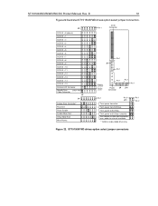
... 1 SCSI ID = 0 (default) SCSI ID = 1 SCSI ID = 2 SCSI ID = 3 SCSI ID = 4 SCSI ID = 5 SCSI ID = 6 SCSI ID = 7 Reserved. power from drive. Parity Disable Enable Motor Start Delay Motor Start Write Protect Remote LED Connector Reserved Negative (cathode) Positive (anode) Pin 1 J01 J4 Spindle Sync Cable Connector SSREF Power Connector Term. power to SCSI bus and drive. Figure 20. 48 ST15150N/ND...
... 1 SCSI ID = 0 (default) SCSI ID = 1 SCSI ID = 2 SCSI ID = 3 SCSI ID = 4 SCSI ID = 5 SCSI ID = 6 SCSI ID = 7 Reserved. power from drive. Parity Disable Enable Motor Start Delay Motor Start Write Protect Remote LED Connector Reserved Negative (cathode) Positive (anode) Pin 1 J01 J4 Spindle Sync Cable Connector SSREF Power Connector Term. power to SCSI bus and drive. Figure 20. 48 ST15150N/ND...

Product Manual
Page 59
... Default is no jumper. 11 & 12 13 & 14 15 & 16 17 & 18* 19 & 20* 21 & 22* Example: If target ID is no jumper. D 49 ST15150N J01 option jumpers Block Pins Function J01 1& 2 Terminator enable. 3 & 4 Terminator power to the SCSI bus. 5 & 6 Terminator power from the... SCSI host. Default is equal to the external terminator (no jumper on ST15150N/ND drives Pin 6 is Gnd. 3 & 4 Reserved. Parity Disable option. Jumper installed causes parity checking and error reporting to look at the Delay Motor Start ...
... Default is no jumper. 11 & 12 13 & 14 15 & 16 17 & 18* 19 & 20* 21 & 22* Example: If target ID is no jumper. D 49 ST15150N J01 option jumpers Block Pins Function J01 1& 2 Terminator enable. 3 & 4 Terminator power to the SCSI bus. 5 & 6 Terminator power from the... SCSI host. Default is equal to the external terminator (no jumper on ST15150N/ND drives Pin 6 is Gnd. 3 & 4 Reserved. Parity Disable option. Jumper installed causes parity checking and error reporting to look at the Delay Motor Start ...
Product Manual
Page 61
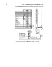
... terminator. * Valid for single-ended drives only. Host adapter or other device provides term. ST15150N/ND/W/WD/WC/DC Product Manual, Rev. Term. J5 SCSI ID = 0 (default) SCSI ID = 1 SCSI ID = 2 SCSI ID = 3 SCSI ID = 4 SCSI ID = 5 SCSI ID = 6 SCSI ID = 7 SCSI ID = 8 SCSI ID = 9 SCSI ID = 10 SCSI ID = 11 SCSI ID = 12 SCSI ID = 13 SCSI ID = 14 SCSI ID = 15 Remote LED Connector Spindle Sync...
... terminator. * Valid for single-ended drives only. Host adapter or other device provides term. ST15150N/ND/W/WD/WC/DC Product Manual, Rev. Term. J5 SCSI ID = 0 (default) SCSI ID = 1 SCSI ID = 2 SCSI ID = 3 SCSI ID = 4 SCSI ID = 5 SCSI ID = 6 SCSI ID = 7 SCSI ID = 8 SCSI ID = 9 SCSI ID = 10 SCSI ID = 11 SCSI ID = 12 SCSI ID = 13 SCSI ID = 14 SCSI ID = 15 Remote LED Connector Spindle Sync...

Product Manual
Page 62
...ST15150N/ND/W/WD/WC/DC Product Manual, Rev. Jumper installed write protects the entire disc drive. No jumper installed causes the unit to be disabled. Jumper installed causes parity checking and error reporting to look at the Delay Motor Start jumper. Pin 9 is anode (pos). Example: If target ID... (no jumper. Jumper installed enables the drive terminator on any of 3 seconds before starting the spindle motor automatically. Pin 10 is cathode (neg). Pin 12 is no jumper. 13 &14 Reserved. Default is Ground. * Valid for each target ID number plus a maximum power-up delay...
...ST15150N/ND/W/WD/WC/DC Product Manual, Rev. Jumper installed write protects the entire disc drive. No jumper installed causes the unit to be disabled. Jumper installed causes parity checking and error reporting to look at the Delay Motor Start jumper. Pin 9 is anode (pos). Example: If target ID... (no jumper. Jumper installed enables the drive terminator on any of 3 seconds before starting the spindle motor automatically. Pin 10 is cathode (neg). Pin 12 is no jumper. 13 &14 Reserved. Default is Ground. * Valid for each target ID number plus a maximum power-up delay...

Product Manual
Page 72
... last four digits of the product serial number. S# Eight ASCII digits representing the eight digits of the product firmware release number. 62 ST15150N/ND/W/WD/WC/DC Product Manual, Rev. Barracuda 4 drives inquiry data (ASA I) Bytes Data (hex) 0-15 00 00 ** *** 8F 00 00 [1A] 53 45 41 47 41 54 45 20... Vendor ID 16-31 53 54 [31 35 31 35 30 4E] 20 20 20 20 20 20 20 20 Product ID 32-47 R# R# R# R# S# S# S# S# S# S# S# S# 00 00...
... last four digits of the product serial number. S# Eight ASCII digits representing the eight digits of the product firmware release number. 62 ST15150N/ND/W/WD/WC/DC Product Manual, Rev. Barracuda 4 drives inquiry data (ASA I) Bytes Data (hex) 0-15 00 00 ** *** 8F 00 00 [1A] 53 45 41 47 41 54 45 20... Vendor ID 16-31 53 54 [31 35 31 35 30 4E] 20 20 20 20 20 20 20 20 Product ID 32-47 R# R# R# R# S# S# S# S# S# S# S# S# 00 00...

Product Manual
Page 92
Eight-bit devices that signal is active low. 2. SCA contact assignments for ST15150WC drives Signal name Connector Connector Signal contact number contact number name 12 VOLT 1 12 VOLT 2 12 VOLT 3 12 VOLT 4... GROUND 73 GROUND 74 5V GROUND 75 5V GROUND 76 5V GROUND 77 ACTIVE LED OUT 78 DLYD_START 79 SCSI ID(1) 80 SCSI ID(3) Notes: 1. The hyphen preceding a signal name indicates that connect to the P cable should be connected as ... DB(13), DB(14), DB(15), DB(P1), DB(8), DB(9), DB(10), and DB(11). 82 ST15150N/ND/W/WD/WC/DC Product Manual, Rev. D Table 18.
Eight-bit devices that signal is active low. 2. SCA contact assignments for ST15150WC drives Signal name Connector Connector Signal contact number contact number name 12 VOLT 1 12 VOLT 2 12 VOLT 3 12 VOLT 4... GROUND 73 GROUND 74 5V GROUND 75 5V GROUND 76 5V GROUND 77 ACTIVE LED OUT 78 DLYD_START 79 SCSI ID(1) 80 SCSI ID(3) Notes: 1. The hyphen preceding a signal name indicates that connect to the P cable should be connected as ... DB(13), DB(14), DB(15), DB(P1), DB(8), DB(9), DB(10), and DB(11). 82 ST15150N/ND/W/WD/WC/DC Product Manual, Rev. D Table 18.

Product Manual
Page 93
...hyphen preceding a signal name indicates that signal is active low. SCA contact assignments for ST15150DC drives Signal name Connector Connector Signal contact number contact number name 12 VOLT 1 12 VOLT 2 12...32 − DB (12) 33 5 VOLT 34 5 VOLT 35 5 VOLT 36 SYNC 37 RMT_START 38 SCSI ID(0) 39 SCSI ID(2) 40 41 12V GROUND 42 12V GROUND 43 12V GROUND 44 12V GROUND 45 RESERVED/NC 46 DIFF SENSE 47 ...GROUND 76 5V GROUND 77 ACTIVE LED OUT 78 DLYD_START 79 SCSI ID(1) 80 SCSI ID(3) Note: 1. D 83 Table 19. ST15150N/ND/W/WD/WC/DC Product Manual, Rev.
...hyphen preceding a signal name indicates that signal is active low. SCA contact assignments for ST15150DC drives Signal name Connector Connector Signal contact number contact number name 12 VOLT 1 12 VOLT 2 12...32 − DB (12) 33 5 VOLT 34 5 VOLT 35 5 VOLT 36 SYNC 37 RMT_START 38 SCSI ID(0) 39 SCSI ID(2) 40 41 12V GROUND 42 12V GROUND 43 12V GROUND 44 12V GROUND 45 RESERVED/NC 46 DIFF SENSE 47 ...GROUND 76 5V GROUND 77 ACTIVE LED OUT 78 DLYD_START 79 SCSI ID(1) 80 SCSI ID(3) Note: 1. D 83 Table 19. ST15150N/ND/W/WD/WC/DC Product Manual, Rev.
