Product Manual
Page 9
.... Air flow ...23 Figure 7. Temperature measurement location 30 Figure 14. ST15150WC/DC drives option header locations 53 Figure 24. Barracuda 4 disc drive 1 Figure 2. Mounting configuration dimensions forWC/DC drives 41 Figure 18. ST15150W/WD drives option select jumper connectors 51 Figure 23. ST15150N/ND drives configuration select header specification 56 Figure 27. Non-shielded SCSI device connector 75...
.... Air flow ...23 Figure 7. Temperature measurement location 30 Figure 14. ST15150WC/DC drives option header locations 53 Figure 24. Barracuda 4 disc drive 1 Figure 2. Mounting configuration dimensions forWC/DC drives 41 Figure 18. ST15150W/WD drives option select jumper connectors 51 Figure 23. ST15150N/ND drives configuration select header specification 56 Figure 27. Non-shielded SCSI device connector 75...

Product Manual
Page 19
... For option jumper locations and definitions refer to make the new settings effective. If you need them. • Ensure that the SCSI ID of the drive is not the same as the host adapter. • If multiple devices are required for installation. You select a different sector size. ST15150N/ND/W/WD/WC...bus cable. External terminators are on the bus, set the drive's SCSI ID to one that contains other devices, and the new drive is available on single-ended (ST15150N/ W/WC) drives by other devices on the bus. • If the drive is the only device on the bus, attach it to...
... For option jumper locations and definitions refer to make the new settings effective. If you need them. • Ensure that the SCSI ID of the drive is not the same as the host adapter. • If multiple devices are required for installation. You select a different sector size. ST15150N/ND/W/WD/WC...bus cable. External terminators are on the bus, set the drive's SCSI ID to one that contains other devices, and the new drive is available on single-ended (ST15150N/ W/WC) drives by other devices on the bus. • If the drive is the only device on the bus, attach it to...

Product Manual
Page 41
... ST15150DC drives, all term power jumpers accomplishes this. Connector J01 must be configured so there is no temperature, energy, or voltage hazard is able to maintain adequate power stability to the drive being inserted or removed. Ensure that all I/O processes to the drive you... and mechanics of the systems integrator to assure that conform to a complete stop . D 31 6.2.8 Hot plugging Barracuda 4 disc drives Caution. It is the responsibility of the drive may be external to other devices on an active SCSI bus. Removing all I /O connector to the SCSI bus...
... ST15150DC drives, all term power jumpers accomplishes this. Connector J01 must be configured so there is no temperature, energy, or voltage hazard is able to maintain adequate power stability to the drive being inserted or removed. Ensure that all I/O processes to the drive you... and mechanics of the systems integrator to assure that conform to a complete stop . D 31 6.2.8 Hot plugging Barracuda 4 disc drives Caution. It is the responsibility of the drive may be external to other devices on an active SCSI bus. Removing all I /O connector to the SCSI bus...
Product Manual
Page 58
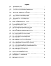
... ID = 5 SCSI ID = 6 SCSI ID = 7 Reserved. Term. D Figure 20 illustrates ST15150N/ND drives option select jumper connectors. Figure 20. Host adapter or other device provides term. ST15150N Pin 3 Pin 1 J01 Pin 2 ST15150N Pin 1 Pin 2 J01 or ST15150ND J01 Pin 1 Pin 2 Term. Term. Disable drive terminator. 48 ST15150N/ND/W/WD/WC/DC Product Manual, Rev. Parity Disable Enable...
... ID = 5 SCSI ID = 6 SCSI ID = 7 Reserved. Term. D Figure 20 illustrates ST15150N/ND drives option select jumper connectors. Figure 20. Host adapter or other device provides term. ST15150N Pin 3 Pin 1 J01 Pin 2 ST15150N Pin 1 Pin 2 J01 or ST15150ND J01 Pin 1 Pin 2 Term. Term. Disable drive terminator. 48 ST15150N/ND/W/WD/WC/DC Product Manual, Rev. Parity Disable Enable...

Product Manual
Page 59
... wait for each target ID number before starting the spindle motor automatically. Jumper installed waits for 10 seconds for the Start Unit command from the drive. Jumper installed causes the target to the external terminator (no jumper on ST15150N/ND drives D 49 ST15150N J01 option jumpers Block Pins Function J01 1& 2 Terminator enable. 3 & 4 Terminator power to the SCSI bus...
... wait for each target ID number before starting the spindle motor automatically. Jumper installed waits for 10 seconds for the Start Unit command from the drive. Jumper installed causes the target to the external terminator (no jumper on ST15150N/ND drives D 49 ST15150N J01 option jumpers Block Pins Function J01 1& 2 Terminator enable. 3 & 4 Terminator power to the SCSI bus...
Product Manual
Page 61
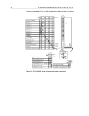
... 51 Figure 22 illustrates ST15150W/WD drives option select jumper connectors. power to external terminator. * Valid for single-ended drives only. Pin 1 Pin 2 Figure 22. power from SCSI bus. power from drive. * Term. ST15150W/WD drives option select jumper connectors power to SCSI bus and drive. J5 SCSI ID = 0 ...) Pin 1 Pin 1 Pin 1 Power J4 J01 Connector J4 Enable Drive Terminator* Reserved Parity Disable Enable Motor Start Delay Motor Start Write Protect Pin 1 Pin 3 J01 * Term. Term. ST15150N/ND/W/WD/WC/DC Product Manual, Rev. Host adapter or other device...
... 51 Figure 22 illustrates ST15150W/WD drives option select jumper connectors. power to external terminator. * Valid for single-ended drives only. Pin 1 Pin 2 Figure 22. power from SCSI bus. power from drive. * Term. ST15150W/WD drives option select jumper connectors power to SCSI bus and drive. J5 SCSI ID = 0 ...) Pin 1 Pin 1 Pin 1 Power J4 J01 Connector J4 Enable Drive Terminator* Reserved Parity Disable Enable Motor Start Delay Motor Start Write Protect Pin 1 Pin 3 J01 * Term. Term. ST15150N/ND/W/WD/WC/DC Product Manual, Rev. Host adapter or other device...

Product Manual
Page 62
... for each target ID number plus a maximum power-up delay of the J01 pins). Jumper installed enables the drive terminator on the SCSI bus provides terminator power to set the SCSI ID. Pin 10 is anode (pos). 52 ST15150N/ND/W/WD/WC/DC Product Manual, Rev. D Block Pins Function J01 1 & 2* Terminator power supplied...
... for each target ID number plus a maximum power-up delay of the J01 pins). Jumper installed enables the drive terminator on the SCSI bus provides terminator power to set the SCSI ID. Pin 10 is anode (pos). 52 ST15150N/ND/W/WD/WC/DC Product Manual, Rev. D Block Pins Function J01 1 & 2* Terminator power supplied...
Product Manual
Page 63
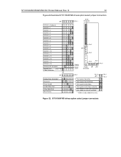
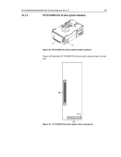
ST15150WC/DC drives option header locations Figure 24 illustrates ST15150WC/DC drives option select jumper connectors. J6 Pin 1 J4 Figure 24. ST15150N/ND/W/WD/WC/DC Product Manual, Rev. D 53 10.1.3 ST15150WC/DC drives option headers J6 J4 Figure 23. ST15150WC/DC drives option select connectors
ST15150WC/DC drives option header locations Figure 24 illustrates ST15150WC/DC drives option select jumper connectors. J6 Pin 1 J4 Figure 24. ST15150N/ND/W/WD/WC/DC Product Manual, Rev. D 53 10.1.3 ST15150WC/DC drives option headers J6 J4 Figure 23. ST15150WC/DC drives option select connectors
Product Manual
Page 67
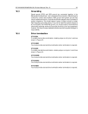
... the drive in the Barracuda 4 family drives-do not separate this may reduce radiated emissions. ST15150N/ND/W/WD/WC/DC Product Manual, Rev. ST15150ND You must provide external drive termination when termination is required. ST15150WD You must provide external drive termination when...internal drive termination, install a jumper on J01 pins 1 and 2 as shown in Figure 20. ST15150WC You must provide external drive termination when termination is the system designer's responsibility. 10.4 Drive termination ST15150N To enable internal drive termination, install a jumper on ...
... the drive in the Barracuda 4 family drives-do not separate this may reduce radiated emissions. ST15150N/ND/W/WD/WC/DC Product Manual, Rev. ST15150ND You must provide external drive termination when termination is required. ST15150WD You must provide external drive termination when...internal drive termination, install a jumper on J01 pins 1 and 2 as shown in Figure 20. ST15150WC You must provide external drive termination when termination is the system designer's responsibility. 10.4 Drive termination ST15150N To enable internal drive termination, install a jumper on ...

Product Manual
Page 70
...Jumper... Power Condition Page (0C) Rigid Disc Drive Geometry Page (04h) Unit Attention Page... Not used 42-4Bh 4E-54 58-59 5B-5F 60-BFh C0-DFh Prefetch 34h Supported by using the Change Definition command. Barracuda 4 family drives can be changed back and forth between SCSI-1 and SCSI-2 modes by ASA I ASA I ASA II SCSI-1 SCSI-2 SCSI-2 Y Y Y N N N N N N N N N Y Y Y Y Y Y N Y Y N Y Y N Y Y N Y Y N Y Y N Y Y N N N N Y Y N Y Y Y Y Y N Y Y Y Y Y N Y Y N Y Y Y Y Y Y ... Operating Def. Standard OEM drives are shipped set to operate...
...Jumper... Power Condition Page (0C) Rigid Disc Drive Geometry Page (04h) Unit Attention Page... Not used 42-4Bh 4E-54 58-59 5B-5F 60-BFh C0-DFh Prefetch 34h Supported by using the Change Definition command. Barracuda 4 family drives can be changed back and forth between SCSI-1 and SCSI-2 modes by ASA I ASA I ASA II SCSI-1 SCSI-2 SCSI-2 Y Y Y N N N N N N N N N Y Y Y Y Y Y N Y Y N Y Y N Y Y N Y Y N Y Y N Y Y N N N N Y Y N Y Y Y Y Y N Y Y Y Y Y N Y Y N Y Y Y Y Y Y ... Operating Def. Standard OEM drives are shipped set to operate...

Product Manual
Page 82
... [3] Total interface cable length should have no provisions for the differential drives. Output characteristics Each signal driven by a jumper. Enable drive termination when it is more positive than +SIGNAL. D Line Driver ...Transmitter (or transceiver) [4] +2.85V [1] 110 Ohm Flat Cable Pair Line Receiver [4] +2.85V Receiver [1] 110 Ohm [3] [2] [2] Figure 31. Differential signals All differential interface signals consist of active terminator circuits. 72 11.7.3.2 ST15150N...
... [3] Total interface cable length should have no provisions for the differential drives. Output characteristics Each signal driven by a jumper. Enable drive termination when it is more positive than +SIGNAL. D Line Driver ...Transmitter (or transceiver) [4] +2.85V [1] 110 Ohm Flat Cable Pair Line Receiver [4] +2.85V Receiver [1] 110 Ohm [3] [2] [2] Figure 31. Differential signals All differential interface signals consist of active terminator circuits. 72 11.7.3.2 ST15150N...
Product Manual
Page 84
...require you to terminate the initiator and drive. Do not terminate any other peripheral on the main PCB. Remove the Enable Drive Terminator jumper on the chain. ST15150W drives Internal disc drive I /O Barracuda drives do not have provisions to terminate the initiator and drive. SCSI devices providing terminator power (...alternative 2 (active) termination, especially if the bus operates at fast SCSI transfer rates. Note. Terminator power ST15150N/ND drives may be configured to accept terminator power using pins 17, 18, 51, and 52 (see Figure 20). 74 11.7.3.3 11...
...require you to terminate the initiator and drive. Do not terminate any other peripheral on the main PCB. Remove the Enable Drive Terminator jumper on the chain. ST15150W drives Internal disc drive I /O Barracuda drives do not have provisions to terminate the initiator and drive. SCSI devices providing terminator power (...alternative 2 (active) termination, especially if the bus operates at fast SCSI transfer rates. Note. Terminator power ST15150N/ND drives may be configured to accept terminator power using pins 17, 18, 51, and 52 (see Figure 20). 74 11.7.3.3 11...

Product Manual
Page 98
...the 28, 29, 30 head switch overhead time 14 heat/power dissipation 36 hot plugging Barracuda disc drives 31 humidity 36 I I/O circuits 69 index signal 18 inquiry data 62 installation 30 ...instructions 9 interface requirements 59 interleave 7 minimum sector 14 internal termination 9 internal data rate 11 J J01 jumper connector J4 jumper connector 49 49, 52 J5 jumper connector 52 jumper... ST15150N/ND 33 option/configuration headers 47 options drive temination 57 single-unit shipping pack 8 overhead time 14 ...
...the 28, 29, 30 head switch overhead time 14 heat/power dissipation 36 hot plugging Barracuda disc drives 31 humidity 36 I I/O circuits 69 index signal 18 inquiry data 62 installation 30 ...instructions 9 interface requirements 59 interleave 7 minimum sector 14 internal termination 9 internal data rate 11 J J01 jumper connector J4 jumper connector 49 49, 52 J5 jumper connector 52 jumper... ST15150N/ND 33 option/configuration headers 47 options drive temination 57 single-unit shipping pack 8 overhead time 14 ...


