
Assembly Manual
Page 4
Some parts are packaged on the outside of Contents Hardware 2 Exploded View 4 Parts List 5 Assembly Instructions 6 Important Contact Numbers 18 Attention! CONTENTS Table of the styrofoam packaging. 1 When unpacking the box, please inspect all styrofoam and packaging before discarding.
Some parts are packaged on the outside of Contents Hardware 2 Exploded View 4 Parts List 5 Assembly Instructions 6 Important Contact Numbers 18 Attention! CONTENTS Table of the styrofoam packaging. 1 When unpacking the box, please inspect all styrofoam and packaging before discarding.
Assembly Manual
Page 5
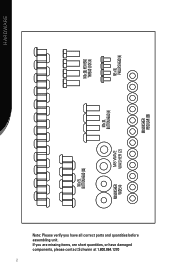
Hardware M8 x 20L HEX HEAD THREAD LOCK (4) M5 x 10L PHILLIPS HEAD (4) M8 WASHER REGULAR (36) M8 x 20L BUTTON HEAD (4) M8 WAVE WASHER (2) M8 x 15L BUTTON HEAD (32) M8 WASHER WIDE (4) Note: Please verify you are missing items, are short quantities, or have all correct parts and quantities before assembling unit. If you have damaged components, please contact Schwinn at 1.800.864.1270 2
Hardware M8 x 20L HEX HEAD THREAD LOCK (4) M5 x 10L PHILLIPS HEAD (4) M8 WASHER REGULAR (36) M8 x 20L BUTTON HEAD (4) M8 WAVE WASHER (2) M8 x 15L BUTTON HEAD (32) M8 WASHER WIDE (4) Note: Please verify you are missing items, are short quantities, or have all correct parts and quantities before assembling unit. If you have damaged components, please contact Schwinn at 1.800.864.1270 2
Assembly Manual
Page 6
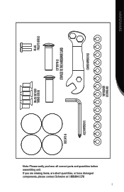
If you have damaged components, please contact Schwinn at 1.800.864.1270 3 HARDWARE M5 x 20L PHILLIPS HEAD (2) COMBO WRENCH (2) COTTER PIN (2) STAPLED TO THE HARDWARE CARD M8 WASHER LOCKING (40) REGULAR (36) M8 x 25L FLAT HEAD THREAD LOCK (6) END CAPS (4) ALLEN WRENCH (1) Note: Please verify you are missing items, are short quantities, or have all correct parts and quantities before assembling unit.
If you have damaged components, please contact Schwinn at 1.800.864.1270 3 HARDWARE M5 x 20L PHILLIPS HEAD (2) COMBO WRENCH (2) COTTER PIN (2) STAPLED TO THE HARDWARE CARD M8 WASHER LOCKING (40) REGULAR (36) M8 x 25L FLAT HEAD THREAD LOCK (6) END CAPS (4) ALLEN WRENCH (1) Note: Please verify you are missing items, are short quantities, or have all correct parts and quantities before assembling unit.
Assembly Manual
Page 8
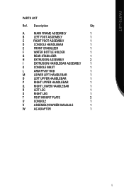
PARTS LIST PARTS LIST Ref. Description Qty A Main Frame Assembly 1 B Left Foot Assembly 1 C Right Foot Assembly 1 D Console HandleBAR 1 E Front Stabilizer 1 F Water Bottle Holder 1 G Rear Stabilizer 1 H Extrusion Assembly 2 I Extrusion ...
PARTS LIST PARTS LIST Ref. Description Qty A Main Frame Assembly 1 B Left Foot Assembly 1 C Right Foot Assembly 1 D Console HandleBAR 1 E Front Stabilizer 1 F Water Bottle Holder 1 G Rear Stabilizer 1 H Extrusion Assembly 2 I Extrusion ...
Assembly Manual
Page 10
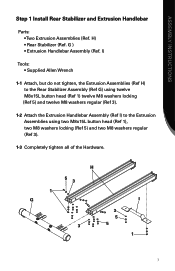
... (Ref 3). 1-2 Attach the Extrusion Handlebar Assembly (Ref I 3 5 3 5 1 7 G ) • Extrusion Handlebar Assembly (Ref. H) • Rear Stabilizer (Ref. ASSEMBLY INSTRUCTIONS Step 1 Install Rear Stabilizer and Extrusion Handlebar Parts: • Two Extrusion Assemblies (Ref.
... (Ref 3). 1-2 Attach the Extrusion Handlebar Assembly (Ref I 3 5 3 5 1 7 G ) • Extrusion Handlebar Assembly (Ref. H) • Rear Stabilizer (Ref. ASSEMBLY INSTRUCTIONS Step 1 Install Rear Stabilizer and Extrusion Handlebar Parts: • Two Extrusion Assemblies (Ref.
Assembly Manual
Page 11
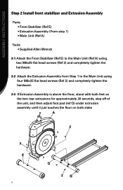
ASSEMBLY INSTRUCTIONS Step 2 Install front stabilizer and Extrusion Assembly Parts: • Front Stabilizer (Ref E) • Extrusion Assembly (From step 1) • Main Unit (Ref A) Tools Supplied Allen Wrench 2-1 Attach the Front Stabilizer (Ref E) to the Main ...
ASSEMBLY INSTRUCTIONS Step 2 Install front stabilizer and Extrusion Assembly Parts: • Front Stabilizer (Ref E) • Extrusion Assembly (From step 1) • Main Unit (Ref A) Tools Supplied Allen Wrench 2-1 Attach the Front Stabilizer (Ref E) to the Main ...
Assembly Manual
Page 12
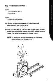
ASSEMBLY INSTRUCTIONS Step 3 Install Console Mast Parts: • Console Mast (Ref K) Main Unit Tools Supplied Allen Wrench 3-1 Connect the wire harness from the Main Unit to pinch the wires when sliding the Console Mast onto the Main Unit K 3 5 1 9 NOTE: Be careful not to the wire harness in the Console Mast. 3-2 Slide the Console Mast (Ref K) down onto the Main Unit and secure using six M8x15L button head (Ref 1), six M8 washers regular (Ref 3) and six M8 washers locking (Ref 5).
ASSEMBLY INSTRUCTIONS Step 3 Install Console Mast Parts: • Console Mast (Ref K) Main Unit Tools Supplied Allen Wrench 3-1 Connect the wire harness from the Main Unit to pinch the wires when sliding the Console Mast onto the Main Unit K 3 5 1 9 NOTE: Be careful not to the wire harness in the Console Mast. 3-2 Slide the Console Mast (Ref K) down onto the Main Unit and secure using six M8x15L button head (Ref 1), six M8 washers regular (Ref 3) and six M8 washers locking (Ref 5).
Assembly Manual
Page 13
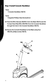
ASSEMBLY INSTRUCTIONS Step 4 Install Console Handlebar Parts: • Console Handlebar (Ref D) Tools Supplied Phillips Head Screwdriver 4-1 Feed the Wire Harness (Ref W1) from the Mast (Ref K) and the Contact Heart Rate Wire (Ref W2) from the Console Handlebar through the hole in the Console Handlebar (Ref D). 4-2 Secure the Console Handlebar to the Mast using four M5x10L phillps screws (Ref 8). 8 W2 D W1 K 10
ASSEMBLY INSTRUCTIONS Step 4 Install Console Handlebar Parts: • Console Handlebar (Ref D) Tools Supplied Phillips Head Screwdriver 4-1 Feed the Wire Harness (Ref W1) from the Mast (Ref K) and the Contact Heart Rate Wire (Ref W2) from the Console Handlebar through the hole in the Console Handlebar (Ref D). 4-2 Secure the Console Handlebar to the Mast using four M5x10L phillps screws (Ref 8). 8 W2 D W1 K 10
Assembly Manual
Page 14
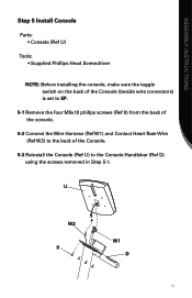
U W2 9 W1 D 11 ASSEMBLY INSTRUCTIONS Step 5 Install Console Parts: • Console (Ref U) Tools Supplied Phillips Head Screwdriver NOTE: Before installing the console, make sure the toggle switch on the back of the Console (beside wire connectors) is set to EP. 5-1 Remove the four M5x10 phillps screws (Ref 9) from the back of the console. 5-2 Connect the Wire Harness (Ref W1) and Contact Heart Rate Wire (Ref W2) to the back of the Console. 5-3 Reinstall the Console (Ref U) to the Console Handlebar (Ref D) using the screws removed in Step 5-1.
U W2 9 W1 D 11 ASSEMBLY INSTRUCTIONS Step 5 Install Console Parts: • Console (Ref U) Tools Supplied Phillips Head Screwdriver NOTE: Before installing the console, make sure the toggle switch on the back of the Console (beside wire connectors) is set to EP. 5-1 Remove the four M5x10 phillps screws (Ref 9) from the back of the console. 5-2 Connect the Wire Harness (Ref W1) and Contact Heart Rate Wire (Ref W2) to the back of the Console. 5-3 Reinstall the Console (Ref U) to the Console Handlebar (Ref D) using the screws removed in Step 5-1.
Assembly Manual
Page 15
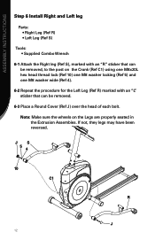
ASSEMBLY INSTRUCTIONS Step 6 Install Right and Left leg Parts: • Right Leg (Ref R) • Left Leg (Ref S) Tools Supplied Combo Wrench 6-1 Attach the Right leg (Ref S), marked with an "L" sticker that can be removed, ...
ASSEMBLY INSTRUCTIONS Step 6 Install Right and Left leg Parts: • Right Leg (Ref R) • Left Leg (Ref S) Tools Supplied Combo Wrench 6-1 Attach the Right leg (Ref S), marked with an "L" sticker that can be removed, ...
Assembly Manual
Page 16
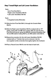
ASSEMBLY INSTRUCTIONS Step 7 Install Right and Left Lower Handlebars Parts Arm Pivot Rod (Ref L Right Lower Handlebar (Ref Q Left Lower Handlebar (Ref M) Tools 2 Supplied Combo Wrenches 7-1 Slide the Arm Pivot Rod (Ref L) through the Console ...
ASSEMBLY INSTRUCTIONS Step 7 Install Right and Left Lower Handlebars Parts Arm Pivot Rod (Ref L Right Lower Handlebar (Ref Q Left Lower Handlebar (Ref M) Tools 2 Supplied Combo Wrenches 7-1 Slide the Arm Pivot Rod (Ref L) through the Console ...
Assembly Manual
Page 17
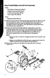
... (Ref 5) and three M8 washers regular(Ref 3). 8-2 Position the Left Foot Assembly (Ref B), marked with an "R". ASSEMBLY INSTRUCTIONS Step 8 Install Right and Left Foot Assembly Parts Foot Mount Plate Qty.2 (Ref T Right Foot Assembly (Ref C Left Foot Assembly (Ref B Arm Cotter Pin (Ref N) Tools Supplied Allen Wrench 8-1 Slide the shaft under...
... (Ref 5) and three M8 washers regular(Ref 3). 8-2 Position the Left Foot Assembly (Ref B), marked with an "R". ASSEMBLY INSTRUCTIONS Step 8 Install Right and Left Foot Assembly Parts Foot Mount Plate Qty.2 (Ref T Right Foot Assembly (Ref C Left Foot Assembly (Ref B Arm Cotter Pin (Ref N) Tools Supplied Allen Wrench 8-1 Slide the shaft under...
Assembly Manual
Page 18
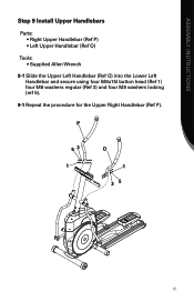
ASSEMBLY INSTRUCTIONS Step 9 Install Upper Handlebars Parts: • Right Upper Handlebar (Ref P) • Left Upper Handlebar (Ref O) Tools Supplied Allen Wrench 9-1 Slide the Upper Left Handlebar (Ref O) into the Lower Left Handlebar and secure using four M8x15l button head (Ref 1) four M8 washers regular (Ref 3) and four M8 washers locking (ref 5). 9-1 Repeat the procedure for the Upper Right Handlebar (Ref P). P 53 1 O 1 35 15
ASSEMBLY INSTRUCTIONS Step 9 Install Upper Handlebars Parts: • Right Upper Handlebar (Ref P) • Left Upper Handlebar (Ref O) Tools Supplied Allen Wrench 9-1 Slide the Upper Left Handlebar (Ref O) into the Lower Left Handlebar and secure using four M8x15l button head (Ref 1) four M8 washers regular (Ref 3) and four M8 washers locking (ref 5). 9-1 Repeat the procedure for the Upper Right Handlebar (Ref P). P 53 1 O 1 35 15
Assembly Manual
Page 19
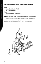
ASSEMBLY INSTRUCTIONS Step 10 Install Water Bottle Holder and AC Adapter Parts: • Water Bottle Holder (Ref F) • AC Adapter (Ref W) Tools Supplied Phillips Screwdriver 10-1 Align the Water Bottle Holder components (Ref F) with the Mast as shown and secure using two M5x20 phillips head (Ref 7). 10-2 Connect the AC Adapter (Ref W) to the unit as shown. F 16 7 F
ASSEMBLY INSTRUCTIONS Step 10 Install Water Bottle Holder and AC Adapter Parts: • Water Bottle Holder (Ref F) • AC Adapter (Ref W) Tools Supplied Phillips Screwdriver 10-1 Align the Water Bottle Holder components (Ref F) with the Mast as shown and secure using two M5x20 phillips head (Ref 7). 10-2 Connect the AC Adapter (Ref W) to the unit as shown. F 16 7 F

Owner's Manual
Page 2
... should enable you to shape and monitor your workouts to rely on -board digital computer enables you for making the Schwinn® elliptical trainer a part of body fat Whether you are just getting started . Also included are already in good shape, this Owner's Manual in an exercise program or are ...
... should enable you to shape and monitor your workouts to rely on -board digital computer enables you for making the Schwinn® elliptical trainer a part of body fat Whether you are just getting started . Also included are already in good shape, this Owner's Manual in an exercise program or are ...
Owner's Manual
Page 4
...I�N�G�S 1. If, at any time, you are near the machine or present during its operation. This machine contains moving parts. Do not use if you feel faint or dizzy, or experience pain, stop and consult your physician. 5. Disconnect all Warnings on ...respective responsibilities. Care should be taken when mounting and dismounting the Elliptical exercise machine. Do not wear loose clothing or jewelry. 7. Contact Nautilus Customer Service. 6. Keep children away from this condition. Moving parts that may appear to present obvious hazards to adults may not...
...I�N�G�S 1. If, at any time, you are near the machine or present during its operation. This machine contains moving parts. Do not use if you feel faint or dizzy, or experience pain, stop and consult your physician. 5. Disconnect all Warnings on ...respective responsibilities. Care should be taken when mounting and dismounting the Elliptical exercise machine. Do not wear loose clothing or jewelry. 7. Contact Nautilus Customer Service. 6. Keep children away from this condition. Moving parts that may appear to present obvious hazards to adults may not...
Owner's Manual
Page 23
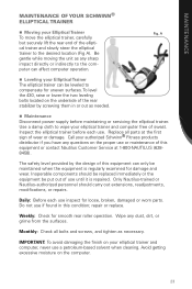
... Maintenance Disconnect power supply before each use until it is regularly examined for smooth rear roller operation. To level the 430, raise or lower the two leveling bolts located on the underside of the rear stabilizer by the design of this ... parts. Only Nautilus-trained or Nautilus-authorized personnel should be replaced immediately or the equipment be leveled to wipe your elliptical trainer and computer, never use a petroleum-based solvent when cleaning. Fig. MAINTENANCE MAINTENANCE OF YOUR SCHWINN® ELLIPTICAL TRAINER Moving your authorized Schwinn&#...
... Maintenance Disconnect power supply before each use until it is regularly examined for smooth rear roller operation. To level the 430, raise or lower the two leveling bolts located on the underside of the rear stabilizer by the design of this ... parts. Only Nautilus-trained or Nautilus-authorized personnel should be replaced immediately or the equipment be leveled to wipe your elliptical trainer and computer, never use a petroleum-based solvent when cleaning. Fig. MAINTENANCE MAINTENANCE OF YOUR SCHWINN® ELLIPTICAL TRAINER Moving your authorized Schwinn&#...
Owner's Manual
Page 25
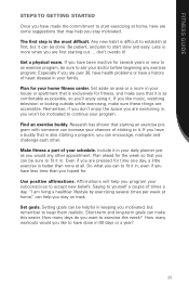
... of your subconscious to fit it ! Research has shown that you like music, watching television or looking outside while exercising, make this week? Make fitness a part of sticking to have been inactive for the week so that starting a program, you can help you motivated, but remember to establish at home," can...
... of your subconscious to fit it ! Research has shown that you like music, watching television or looking outside while exercising, make this week? Make fitness a part of sticking to have been inactive for the week so that starting a program, you can help you motivated, but remember to establish at home," can...
Owner's Manual
Page 27
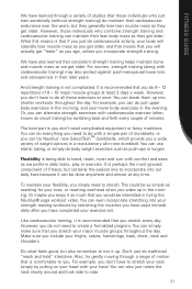
..., which provide you a wide variety of dumbbells, or you can also just rotate the neck slowly around and look side to side. 27 The best part is being able to bend, reach, twist and turn with comfort and ease as we get "fatter" as we perform daily tasks, play or exercise...
..., which provide you a wide variety of dumbbells, or you can also just rotate the neck slowly around and look side to side. 27 The best part is being able to bend, reach, twist and turn with comfort and ease as we get "fatter" as we perform daily tasks, play or exercise...
Owner's Manual
Page 34
...in connection with this warranty or, at Nautilus's election, to repair an exercise product or part yourself, using the services of someone other warranties not expressly set forth by Schwinn® Fitness warranty policies and procedures. frame 2 year - shall in materials and workmanship....caused by Nautilus, Nautilus shall not be free from the Authorized Schwinn® Dealer is the responsibility of equal or greater value. 4. Nautilus is not responsible for assistance or questions. 34 mechanical parts 1 year - The original purchaser must provide proof of purchase ...
...in connection with this warranty or, at Nautilus's election, to repair an exercise product or part yourself, using the services of someone other warranties not expressly set forth by Schwinn® Fitness warranty policies and procedures. frame 2 year - shall in materials and workmanship....caused by Nautilus, Nautilus shall not be free from the Authorized Schwinn® Dealer is the responsibility of equal or greater value. 4. Nautilus is not responsible for assistance or questions. 34 mechanical parts 1 year - The original purchaser must provide proof of purchase ...


