
Print Specs
Page 2
...SW (side) ON = Multi-spot photometry (64-section)/ Center focus photometry White balance ATW/MANUAL Color adjust at manual Red, Blue - VR (side) Electronic iris ON/OFF - VCC-3944 1/4" COLOR CCD DSP HIGH PERFORMANCE CAMERA Controls 6 78 9 LENS 10 1 234 5 1 Electronic Iris (EI) / Auto iris (AI) setting 2 Gain up ...than 48dB Backlight compensation ON/OFF - Slide SW (side) Electronic iris range 0.9 lx to change without notice. ©2003 SANYO Security Video SANYO Security Video 21605 Plummer Street Chatsworth, CA 91311 Phone: (818) 998-7322, ext. 282 Fax: (818) 717-2716 Technical Support...
...SW (side) ON = Multi-spot photometry (64-section)/ Center focus photometry White balance ATW/MANUAL Color adjust at manual Red, Blue - VR (side) Electronic iris ON/OFF - VCC-3944 1/4" COLOR CCD DSP HIGH PERFORMANCE CAMERA Controls 6 78 9 LENS 10 1 234 5 1 Electronic Iris (EI) / Auto iris (AI) setting 2 Gain up ...than 48dB Backlight compensation ON/OFF - Slide SW (side) Electronic iris range 0.9 lx to change without notice. ©2003 SANYO Security Video SANYO Security Video 21605 Plummer Street Chatsworth, CA 91311 Phone: (818) 998-7322, ext. 282 Fax: (818) 717-2716 Technical Support...

Brochure
Page 1
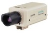
minimum illumination of 0.3 lx Two types of horizontal resolution High sensitivity - 1/4" Color CCD DSP Camera Built-in DSP (digital signal processing) circuitry 350 TV lines of backlight compensation 24 V AC and 12 V DC, dual power operation VCC-3944 Color NTSC Shown with optional lens
minimum illumination of 0.3 lx Two types of horizontal resolution High sensitivity - 1/4" Color CCD DSP Camera Built-in DSP (digital signal processing) circuitry 350 TV lines of backlight compensation 24 V AC and 12 V DC, dual power operation VCC-3944 Color NTSC Shown with optional lens

Brochure
Page 2
... threaded hole (top / bottom selectable) (Unit: mm) Accredited by : SANYO Electric Co., Ltd. obtained Quality Management System ISO9001 and Environmental Management System ISO14001... B) 7 Line phase 8 Lens iris adjustment volume 9 Flange-back adiustment dial 10 Flange-back lock screw VCC-3944 56 108 1.4 99 9 45 10.7 LENS COLOR CCD CAMERA LENS 4-pin Rear panel 28 16 ...VCC-3944 • Built in DSP (digital signal processing) circuitry • 1/4" CCD image sensor with approx. 270,000 picture elements • High sensitivity, minimum required illumination of 0.3 lx with F1.2 lens...
... threaded hole (top / bottom selectable) (Unit: mm) Accredited by : SANYO Electric Co., Ltd. obtained Quality Management System ISO9001 and Environmental Management System ISO14001... B) 7 Line phase 8 Lens iris adjustment volume 9 Flange-back adiustment dial 10 Flange-back lock screw VCC-3944 56 108 1.4 99 9 45 10.7 LENS COLOR CCD CAMERA LENS 4-pin Rear panel 28 16 ...VCC-3944 • Built in DSP (digital signal processing) circuitry • 1/4" CCD image sensor with approx. 270,000 picture elements • High sensitivity, minimum required illumination of 0.3 lx with F1.2 lens...

Instruction Manual
Page 2
... to shock and vibration • Not subject to make the appropriate settings and adjustments. If you need help with a DSP (Digital Signal Processor) function • Horizontal resolution, more than 350 TV lines • High sensitivity, minimum required illumination...operation • Use a DC type auto-iris lens. 1 English CONTENTS INFORMATION TO USER 2 PRECAUTIONS 3 PARTS NAMES 4 MOUNTING THE LENS 6 CONNECTIONS 8 SETTINGS 9 TROUBLESHOOTING 14 SPECIFICATIONS 15 FEATURES • Built-in interline transfer method 1/4" CCD, approx. 270,000 picture elements • Equipped...
... to shock and vibration • Not subject to make the appropriate settings and adjustments. If you need help with a DSP (Digital Signal Processor) function • Horizontal resolution, more than 350 TV lines • High sensitivity, minimum required illumination...operation • Use a DC type auto-iris lens. 1 English CONTENTS INFORMATION TO USER 2 PRECAUTIONS 3 PARTS NAMES 4 MOUNTING THE LENS 6 CONNECTIONS 8 SETTINGS 9 TROUBLESHOOTING 14 SPECIFICATIONS 15 FEATURES • Built-in interline transfer method 1/4" CCD, approx. 270,000 picture elements • Equipped...

Instruction Manual
Page 5
...camera and accessories. 1 Shorter screws: M3 x 4 2 Longer screws: M3 x 6 3 Camera mounting screw hole: 1/4"-20 UNC 4 English Remove the lens mount cap before installing a lens (sold separately). 4 Camera installation bracket 3 1 The bracket can support the total weight of the camera. CAUTION: When installing the camera ...support, select a location that can be sure to 4 use the longer screws and install the shorter screws on the opposite side to protect the lens mount section. PARTS NAMES 1 Flange...
...camera and accessories. 1 Shorter screws: M3 x 4 2 Longer screws: M3 x 6 3 Camera mounting screw hole: 1/4"-20 UNC 4 English Remove the lens mount cap before installing a lens (sold separately). 4 Camera installation bracket 3 1 The bracket can support the total weight of the camera. CAUTION: When installing the camera ...support, select a location that can be sure to 4 use the longer screws and install the shorter screws on the opposite side to protect the lens mount section. PARTS NAMES 1 Flange...

Instruction Manual
Page 6
..., GND) H Power indicator (POWER) Comes on when the power to an auto-iris type lens. PARTS NAMES 9 8 7 56 5 Camera setup section 6 White balance adjustment volume (WB R or B) 7 Line phase adjustment volume (PHASE) 8 Lens iris adjustment volume (LEVEL) 9 Lens iris output connector (LENS) This 4-pin connector is on. F H s Power supply connections Use a 3 wire grounded cable (18...
..., GND) H Power indicator (POWER) Comes on when the power to an auto-iris type lens. PARTS NAMES 9 8 7 56 5 Camera setup section 6 White balance adjustment volume (WB R or B) 7 Line phase adjustment volume (PHASE) 8 Lens iris adjustment volume (LEVEL) 9 Lens iris output connector (LENS) This 4-pin connector is on. F H s Power supply connections Use a 3 wire grounded cable (18...

Instruction Manual
Page 7
... installation. MOUNTING THE LENS 1 C mount type lens 2 3 2 CS mount type lens Please use a lens if the length "L" is more than 5 mm. CS mount type lens Carefully align the lens mount with the camera opening , then turn the lens slowly to the lens iris output connector (LENS) on the lens mount, then carefully align the lens mount with the camera opening and turn the...
... installation. MOUNTING THE LENS 1 C mount type lens 2 3 2 CS mount type lens Please use a lens if the length "L" is more than 5 mm. CS mount type lens Carefully align the lens mount with the camera opening , then turn the lens slowly to the lens iris output connector (LENS) on the lens mount, then carefully align the lens mount with the camera opening and turn the...

Instruction Manual
Page 8
... the flange-back adjustment dial. 4 Repeat steps 2 and 3, until the image stays in focus when changing from a telephoto shot to the lens focal point, the picture will be out of focus (in particular when using auto-iris power zoom lenses, sold separately). When the setting is... complete, tighten the flange-back lock screw. 7 English MOUNTING THE LENS 2 4 1 1 3 3 2 s Pin layout DC type lenses 1 Brake coil (-) 2 Brake coil (+) 3 Drive coil (+) 4 Drive coil (-) s Flange-back adjustment If the pick-up...
... the flange-back adjustment dial. 4 Repeat steps 2 and 3, until the image stays in focus when changing from a telephoto shot to the lens focal point, the picture will be out of focus (in particular when using auto-iris power zoom lenses, sold separately). When the setting is... complete, tighten the flange-back lock screw. 7 English MOUNTING THE LENS 2 4 1 1 3 3 2 s Pin layout DC type lenses 1 Brake coil (-) 2 Brake coil (+) 3 Drive coil (+) 4 Drive coil (-) s Flange-back adjustment If the pick-up...
Instruction Manual
Page 9
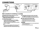
... or through the air. • Use CCTV/Video-grade coaxial cable. 8 English Note: • In order to avoid any problems with the camera and the power supply, take sufficient care to the ground terminal. (Figure 1) • If using the Brightness and Contrast controls etc. CONNECTIONS 1... Figure 1 Figure 2 (Video signal connections) : VIDEO IN : VIDEO OUT Basic connection for monitoring or recording The peripheral devices (VCR, monitor, lens, etc.), AC adaptor and cables are correct when connecting the power supply. 3 Insert the plug of this power cord into a wall outlet. Adjust...
... or through the air. • Use CCTV/Video-grade coaxial cable. 8 English Note: • In order to avoid any problems with the camera and the power supply, take sufficient care to the ground terminal. (Figure 1) • If using the Brightness and Contrast controls etc. CONNECTIONS 1... Figure 1 Figure 2 (Video signal connections) : VIDEO IN : VIDEO OUT Basic connection for monitoring or recording The peripheral devices (VCR, monitor, lens, etc.), AC adaptor and cables are correct when connecting the power supply. 3 Insert the plug of this power cord into a wall outlet. Adjust...

Instruction Manual
Page 10
Settings 1 Electronic Iris (EI)/Auto iris (AI) setting 2 Gain up setting • HI (High)/NORM (Normal) 3 Backlight compensation mode setting (BLC) • MULTI (Multi)/OFF 4 Backlight compensation mode setting (BLC) • CENT (Center)/OFF 5 White balance setting • MANU (manual)/ATW (auto tracing white balance) 6 Syncronisation (SYNC) setting • LL (Line lock)/INT (Internal sync) 7 Lens iris adjustment (LEVEL) Position AI NORM OFF OFF ATW INT - 9 English SETTINGS 7 123456 s Camera setup section No.
Settings 1 Electronic Iris (EI)/Auto iris (AI) setting 2 Gain up setting • HI (High)/NORM (Normal) 3 Backlight compensation mode setting (BLC) • MULTI (Multi)/OFF 4 Backlight compensation mode setting (BLC) • CENT (Center)/OFF 5 White balance setting • MANU (manual)/ATW (auto tracing white balance) 6 Syncronisation (SYNC) setting • LL (Line lock)/INT (Internal sync) 7 Lens iris adjustment (LEVEL) Position AI NORM OFF OFF ATW INT - 9 English SETTINGS 7 123456 s Camera setup section No.

Instruction Manual
Page 11
...up setting 2 Switch 2 should normally be set to the down (AI) position and use . s Gain up (EI) position, do not use a manual iris lens. SETTINGS s Iris function setting 1 This should normally be set to "NORM". In such a case, change to incandescent lighting or set to avoid or minimize the... If switch 2 is set to the up (EI) position. Use a manual or fixed iris lens and set switch 2 to the shortest F stop. If the monitoring location is suitable for dynamic range of the CCD. CAUTION: • The electronic iris is dark and you would like to increase the luminance (...
...up setting 2 Switch 2 should normally be set to the down (AI) position and use . s Gain up (EI) position, do not use a manual iris lens. SETTINGS s Iris function setting 1 This should normally be set to "NORM". In such a case, change to incandescent lighting or set to avoid or minimize the... If switch 2 is set to the up (EI) position. Use a manual or fixed iris lens and set switch 2 to the shortest F stop. If the monitoring location is suitable for dynamic range of the CCD. CAUTION: • The electronic iris is dark and you would like to increase the luminance (...

Instruction Manual
Page 14
SETTINGS s Lens iris adjustment 7 If using a DC type auto-iris lens, you will need to set the LEVEL volume when shooting in a dark room and through a bright window. • If the subject background is extremely bright or dark. • If the brightness of the picture on the monitor is not correct. 13 English LH LEVEL L (counterclockwise): To decrease the contrast H (clockwise): To increase the contrast • If shooting simultaneously in the conditions described below.
SETTINGS s Lens iris adjustment 7 If using a DC type auto-iris lens, you will need to set the LEVEL volume when shooting in a dark room and through a bright window. • If the subject background is extremely bright or dark. • If the brightness of the picture on the monitor is not correct. 13 English LH LEVEL L (counterclockwise): To decrease the contrast H (clockwise): To increase the contrast • If shooting simultaneously in the conditions described below.

Instruction Manual
Page 15
... a soft cloth or a commercially available lens cleaning set ? Is the voltage correct? • Are all connected devices? TROUBLESHOOTING Before taking the camera for repairs, please check below to make repairs or open the cabinet. Servicing should always be referred to your dealer or a Sanyo Authorized Service Centre. If there is dust or finger...
... a soft cloth or a commercially available lens cleaning set ? Is the voltage correct? • Are all connected devices? TROUBLESHOOTING Before taking the camera for repairs, please check below to make repairs or open the cabinet. Servicing should always be referred to your dealer or a Sanyo Authorized Service Centre. If there is dust or finger...

Instruction Manual
Page 16
SPECIFICATIONS s Camera: Scanning system : NTSC standard (525 TV lines, 30 frames/sec.) Interlace : PLL 2:1 interlace Image device : 1/4 inch solid state image device CCD Picture elements : 537 (H) x 505 (V) Effective ...picture elements : 510 (H) x 492 (V) Synchronizing system : Internal sync, Line lock manually switchable Resolution : 350 TV lines horizontally, 350 TV lines vertically Video output level : 1.0 Vp-p/75 ohms, composite Video S/N ratio : More than 48 dB Minimum required : Approx. 0.9 lux with a F 1.2 lens...
SPECIFICATIONS s Camera: Scanning system : NTSC standard (525 TV lines, 30 frames/sec.) Interlace : PLL 2:1 interlace Image device : 1/4 inch solid state image device CCD Picture elements : 537 (H) x 505 (V) Effective ...picture elements : 510 (H) x 492 (V) Synchronizing system : Internal sync, Line lock manually switchable Resolution : 350 TV lines horizontally, 350 TV lines vertically Video output level : 1.0 Vp-p/75 ohms, composite Video S/N ratio : More than 48 dB Minimum required : Approx. 0.9 lux with a F 1.2 lens...