
Product Manual
Page 1
SanDisk CompactFlash Memory Card OEM Product Manual Version 12.0 Document No. 20-10-00038 02/2007 SanDisk Corporation Corporate Headquarters 601 McCarthy Boulevard Milpitas, CA 95035 (408) 801-1000 Phone (408) 801-8657 Fax www.sandisk.com
SanDisk CompactFlash Memory Card OEM Product Manual Version 12.0 Document No. 20-10-00038 02/2007 SanDisk Corporation Corporate Headquarters 601 McCarthy Boulevard Milpitas, CA 95035 (408) 801-1000 Phone (408) 801-8657 Fax www.sandisk.com

Product Manual
Page 7
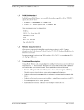
.... In addition to the mass storage-specific flash memory chips, CompactFlash Memory cards include an on -card intelligent controller in a PCMCIA Type II or Type III socket. This interface allows a host computer to issue commands to the memory card to enhance system performance. Once the card has been configured by SanDisk specifically for use SanDisk Flash memory, which was designed by the host...
.... In addition to the mass storage-specific flash memory chips, CompactFlash Memory cards include an on -card intelligent controller in a PCMCIA Type II or Type III socket. This interface allows a host computer to issue commands to the memory card to enhance system performance. Once the card has been configured by SanDisk specifically for use SanDisk Flash memory, which was designed by the host...

Product Manual
Page 8
...,000 hours • Minimum 10,000 insertions 1.3 Scope This document describes the key features and specifications of CompactFlash Memory cards, as well as the information required to interface this manual. 1.4 CompactFlash Standard SanDisk CompactFlash Memory cards are fully compatible with the CompactFlash Specification published by the CompactFlash Association. Retail CompactFlash specifications are not covered in...
...,000 hours • Minimum 10,000 insertions 1.3 Scope This document describes the key features and specifications of CompactFlash Memory cards, as well as the information required to interface this manual. 1.4 CompactFlash Standard SanDisk CompactFlash Memory cards are fully compatible with the CompactFlash Specification published by the CompactFlash Association. Retail CompactFlash specifications are not covered in...
Product Manual
Page 9
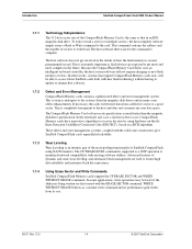
... erasing and programming flash memory. • Sophisticated system for managing defects (analogous to systems found in magnetic disk drives). • Sophisticated system for error recovery including a powerful error correction code (ECC). • Power management for low power operation. • Implementation of memory cards. SanDisk CompactFlash Card OEM Product Manual Introduction 1.5 PCMCIA Standard SanDisk CompactFlash Memory cards are fully electrically...
... erasing and programming flash memory. • Sophisticated system for managing defects (analogous to systems found in magnetic disk drives). • Sophisticated system for error recovery including a powerful error correction code (ECC). • Power management for low power operation. • Implementation of memory cards. SanDisk CompactFlash Card OEM Product Manual Introduction 1.5 PCMCIA Standard SanDisk CompactFlash Memory cards are fully electrically...
Product Manual
Page 10
... used to write/read . This command contains the address and the number of sectors to ensure high data reliability and maximize flash life expectancy. 1.7.4 Using Erase Sector and Write Commands SanDisk CompactFlash Memory cards support the CF ERASE SECTOR and WRITE WITHOUT ERASE commands. In some applications, write operations may be able to access...
... used to write/read . This command contains the address and the number of sectors to ensure high data reliability and maximize flash life expectancy. 1.7.4 Using Erase Sector and Write Commands SanDisk CompactFlash Memory cards support the CF ERASE SECTOR and WRITE WITHOUT ERASE commands. In some applications, write operations may be able to access...

Product Manual
Page 11
... Adjustment of Performance vs. The host does not have to follow the ATA protocol of issuing a reset first. SanDisk CompactFlash Card OEM Product Manual Introduction 1.7.5 Automatic Sleep Mode A unique feature of the SanDisk CompactFlash Memory Card is automatic entrance and exit from command completion to entering sleep mode is adjustable. It may not support this...
... Adjustment of Performance vs. The host does not have to follow the ATA protocol of issuing a reset first. SanDisk CompactFlash Card OEM Product Manual Introduction 1.7.5 Automatic Sleep Mode A unique feature of the SanDisk CompactFlash Memory Card is automatic entrance and exit from command completion to entering sleep mode is adjustable. It may not support this...

Product Manual
Page 14
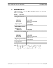
...181; 1.2 mA 100 mA 100 mA 100 mA 02/07, Rev. 12.0 2-2 © 2007 SanDisk Corporation Table 2-2 Power Requirements DC Input Voltage (Vcc) 100 mV max. ripple (p-p) 3.3V +/- 5% Memory Subsystema CompactFlash Memory Card Sleep Up to 512 MB 300 µ 1.0 GB 600 µ Over 1.0 GB 1 mA Read ...Write Peak 100 mA Memory Subsystema CompactFlash Extreme III Memory Card Sleep Up to 512 MB 300 µ 512 MB to 1.5 GB 600 µ Over 1.5 GB 1 mA Read 75 mA Write 75 mA Read/Write Peak 100 mA a. Product Specifications SanDisk CompactFlash Card OEM Product Manual Sleep...
...181; 1.2 mA 100 mA 100 mA 100 mA 02/07, Rev. 12.0 2-2 © 2007 SanDisk Corporation Table 2-2 Power Requirements DC Input Voltage (Vcc) 100 mV max. ripple (p-p) 3.3V +/- 5% Memory Subsystema CompactFlash Memory Card Sleep Up to 512 MB 300 µ 1.0 GB 600 µ Over 1.0 GB 1 mA Read ...Write Peak 100 mA Memory Subsystema CompactFlash Extreme III Memory Card Sleep Up to 512 MB 300 µ 512 MB to 1.5 GB 600 µ Over 1.5 GB 1 mA Read 75 mA Write 75 mA Read/Write Peak 100 mA a. Product Specifications SanDisk CompactFlash Card OEM Product Manual Sleep...
Product Manual
Page 15
... sleep mode. © 2007 SanDisk Corporation 2-3 Rev. 12.0, 02/07 CompactFlash Memory cards do not require a reset to when the card is reading or writing. Table 2-3 Performance CompactFlash Memory Card Start-up Times Sleep to Write Sleep to Read Reset to Ready Active to Sleep Delay Data Transfer Rate To/From Flash Data Transfer Rate To/From...
... sleep mode. © 2007 SanDisk Corporation 2-3 Rev. 12.0, 02/07 CompactFlash Memory cards do not require a reset to when the card is reading or writing. Table 2-3 Performance CompactFlash Memory Card Start-up Times Sleep to Write Sleep to Read Reset to Ready Active to Sleep Delay Data Transfer Rate To/From Flash Data Transfer Rate To/From...
Product Manual
Page 16
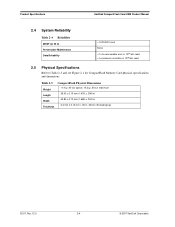
Product Specifications SanDisk CompactFlash Card OEM Product Manual 2.4 System Reliability Table 2-4 Reliability MTBF (@ 25 C) Preventative Maintenance Data Reliability >1,000,000 hours None
Product Specifications SanDisk CompactFlash Card OEM Product Manual 2.4 System Reliability Table 2-4 Reliability MTBF (@ 25 C) Preventative Maintenance Data Reliability >1,000,000 hours None
Product Manual
Page 19
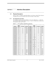
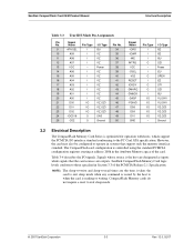
Sections 3.3.1 and 3.3.2 define the DC characteristics for all input and output type structures.. Table 3-1 PC Card Memory Mode Pin Assignments Pin No. 1 2 3 4 5 6 7 8 9 10 11 12 13 14 15 16 17 18 19 20 21 22 ... GND Pin Type O I/O I/O I/O I/O I/O I O I I I - I/O I/O I/O I/O I/O I I I I I I O - Pin types are listed in Table 3-1. CHAPTER 3 Interface Description 3.1 Physical Description The host connects to SanDisk CompactFlash Memory cards using a standard 50-pin connector consisting of two rows of 25 female contacts each on 50 mil (1.27 mm) centers. 3.1.1 Pin Assignments and Types The...
Sections 3.3.1 and 3.3.2 define the DC characteristics for all input and output type structures.. Table 3-1 PC Card Memory Mode Pin Assignments Pin No. 1 2 3 4 5 6 7 8 9 10 11 12 13 14 15 16 17 18 19 20 21 22 ... GND Pin Type O I/O I/O I/O I/O I/O I O I I I - I/O I/O I/O I/O I/O I I I I I I O - Pin types are listed in Table 3-1. CHAPTER 3 Interface Description 3.1 Physical Description The host connects to SanDisk CompactFlash Memory cards using a standard 50-pin connector consisting of two rows of 25 female contacts each on 50 mil (1.27 mm) centers. 3.1.1 Pin Assignments and Types The...
Product Manual
Page 21
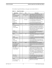
... sleep mode when any command is controlled using the standard PCMCIA configuration registers starting at address 200h in Section 3.3 of the card. SanDisk CompactFlash Card OEM Product Manual Interface Description Table 3-3 True IDE Mode Pin Assignments Pin Signal No. I O I O O I I/O I/O I/O I/O I I1Z 37 13 VCC - SanDisk CompactFlash Memory Card logic levels conform to those specified in the Attribute...
... sleep mode when any command is controlled using the standard PCMCIA configuration registers starting at address 200h in Section 3.3 of the card. SanDisk CompactFlash Card OEM Product Manual Interface Description Table 3-3 True IDE Mode Pin Assignments Pin Signal No. I O I O O I I/O I/O I/O I/O I I1Z 37 13 VCC - SanDisk CompactFlash Memory Card logic levels conform to those specified in the Attribute...
Product Manual
Page 22
... pins are described in the master/ slave handshake protocol. -CD1, -CD2 O (PC Card Memory Mode) (PC Card I /O Mode. 02/07, Rev. 12.0 3-4 © 2007 SanDisk Corporation Interface Description SanDisk CompactFlash Card OEM Product Manual The SanDisk CompactFlash Memory Card signals are connected to the card whether a byte or a word operation is fully inserted into its configuration control and status registers...
... pins are described in the master/ slave handshake protocol. -CD1, -CD2 O (PC Card Memory Mode) (PC Card I /O Mode. 02/07, Rev. 12.0 3-4 © 2007 SanDisk Corporation Interface Description SanDisk CompactFlash Card OEM Product Manual The SanDisk CompactFlash Memory Card signals are connected to the card whether a byte or a word operation is fully inserted into its configuration control and status registers...
Product Manual
Page 24
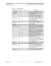
... low for a level mode interrupt. The host memory card socket must also be active (low) during I/O cycles when the I /O operation, this input should be grounded by the host interface. This Attribute Memory Select signal is busy. No access of the signal (trailing edge). Interface Description SanDisk CompactFlash Card OEM Product Manual Table 3-4 Signal Description Signal...
... low for a level mode interrupt. The host memory card socket must also be active (low) during I/O cycles when the I /O operation, this input should be grounded by the host interface. This Attribute Memory Select signal is busy. No access of the signal (trailing edge). Interface Description SanDisk CompactFlash Card OEM Product Manual Table 3-4 Signal Description Signal...
Product Manual
Page 25
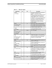
...open from the host. +5V, +3.3V power. In the True IDE Mode this signal resets the card. SanDisk CompactFlash Memory cards, except when in process. In PC Card I /O Mode) -WE (True IDE Mode) WP O (PC Card Memory Mode) 41 13, 38 33, 40 42 36 24 Description This signal is used by the ... time once the DMACK- For Multiword DMA transfers, the device may be negated by the host. SanDisk CompactFlash Memory cards do not assert the -WAIT signal. The card is grounded so that the CompactFlash Card CIS can be connected to VCC by the host to resume DMA operation. Voltage Sense Signals. ...
...open from the host. +5V, +3.3V power. In the True IDE Mode this signal resets the card. SanDisk CompactFlash Memory cards, except when in process. In PC Card I /O Mode) -WE (True IDE Mode) WP O (PC Card Memory Mode) 41 13, 38 33, 40 42 36 24 Description This signal is used by the ... time once the DMACK- For Multiword DMA transfers, the device may be negated by the host. SanDisk CompactFlash Memory cards do not assert the -WAIT signal. The card is grounded so that the CompactFlash Card CIS can be connected to VCC by the host to resume DMA operation. Voltage Sense Signals. ...

Product Manual
Page 26
... = 3.3V +/- 5% Ta = 0 ° C to the characteristics described in the CompactFlash Memory Card Series product to 6.5V max. Interface Description SanDisk CompactFlash Card OEM Product Manual Table 3-4 Signal Description Signal Name Dir. Pin -IOIS16 (PC Card I/O Mode) -IOCS16 (True IDE Mode) Description I/O Operation-When the card is configured for I/O Operation, pin 24 is expecting a word data transfer...
... = 3.3V +/- 5% Ta = 0 ° C to the characteristics described in the CompactFlash Memory Card Series product to 6.5V max. Interface Description SanDisk CompactFlash Card OEM Product Manual Table 3-4 Signal Description Signal Name Dir. Pin -IOIS16 (PC Card I/O Mode) -IOCS16 (True IDE Mode) Description I/O Operation-When the card is configured for I/O Operation, pin 24 is expecting a word data transfer...

Product Manual
Page 29
... ----------- 5 5 0 10 Max. --100 100 50 50 50 --------- © 2007 SanDisk Corporation 3-11 Rev. 12.0, 02/07 NOTE: All timings measured at the CompactFlash Memory Card. trec VIH 2V 3.3.4 Common Memory Read Timing Table 3-10 contains common memory read timing specifications for by pull-up resistor on card (if present) tpf VCC Min. Skews and delays from...
... ----------- 5 5 0 10 Max. --100 100 50 50 50 --------- © 2007 SanDisk Corporation 3-11 Rev. 12.0, 02/07 NOTE: All timings measured at the CompactFlash Memory Card. trec VIH 2V 3.3.4 Common Memory Read Timing Table 3-10 contains common memory read timing specifications for by pull-up resistor on card (if present) tpf VCC Min. Skews and delays from...

Product Manual
Page 30
... a. All timings measured at the CompactFlash Memory Card. The -REG signal timing is identical to the card must be accounted for Common and Attribute memory are the same. Table 3-11 Common and Attribute Memory Write Timing Specification Speed Version Write Cycle ...specifications for by the system NOTE: SanDisk CompactFlash Memory cards do not assert the -WAIT signal. Interface Description SanDisk CompactFlash Card OEM Product Manual Table 3-10 Common Memory Read Timing Specification Speed Version Item Address Hold Time Card Enable Setup Time Card Enable Hold Time Symbol th (A)...
... a. All timings measured at the CompactFlash Memory Card. The -REG signal timing is identical to the card must be accounted for Common and Attribute memory are the same. Table 3-11 Common and Attribute Memory Write Timing Specification Speed Version Write Cycle ...specifications for by the system NOTE: SanDisk CompactFlash Memory cards do not assert the -WAIT signal. Interface Description SanDisk CompactFlash Card OEM Product Manual Table 3-10 Common Memory Read Timing Specification Speed Version Item Address Hold Time Card Enable Setup Time Card Enable Hold Time Symbol th (A)...

Product Manual
Page 31
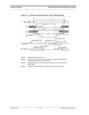
... Max. --300 300 150 100 3.3.7 Memory Timing Diagrams Figure 3-3 Common and Attribute Memory Read Timing Diagram NOTE 1: Shaded areas may be high or low. © 2007 SanDisk Corporation 3-13 Rev. 12.0, 02/07 NOTE: SanDisk CompactFlash Memory cards do not assert the -WAIT signal. SanDisk CompactFlash Card OEM Product Manual Interface Description 3.3.6 Attribute Memory Read Timing Specification Table 3-12...
... Max. --300 300 150 100 3.3.7 Memory Timing Diagrams Figure 3-3 Common and Attribute Memory Read Timing Diagram NOTE 1: Shaded areas may be high or low. © 2007 SanDisk Corporation 3-13 Rev. 12.0, 02/07 NOTE: SanDisk CompactFlash Memory cards do not assert the -WAIT signal. SanDisk CompactFlash Card OEM Product Manual Interface Description 3.3.6 Attribute Memory Read Timing Specification Table 3-12...
Product Manual
Page 32
SanDisk CompactFlash Memory Cards do not assert the -WAIT signal. 02/07, Rev. 12.0 3-14 © 2007 SanDisk Corporation When the data I/O pins are in the output state, no signals shall be applied to the data pins (D[15::0]) by the host system May be high or low. Interface Description SanDisk CompactFlash Card OEM Product Manual Figure 3-4 Common and Attribute Memory Write Timing Diagram NOTE 1: NOTE 2: NOTE 3: NOTE 4: Shaded areas may be high or low for write timing, but restrictions on -OE from previous figures apply.
SanDisk CompactFlash Memory Cards do not assert the -WAIT signal. 02/07, Rev. 12.0 3-14 © 2007 SanDisk Corporation When the data I/O pins are in the output state, no signals shall be applied to the data pins (D[15::0]) by the host system May be high or low. Interface Description SanDisk CompactFlash Card OEM Product Manual Figure 3-4 Common and Attribute Memory Write Timing Diagram NOTE 1: NOTE 2: NOTE 3: NOTE 4: Shaded areas may be high or low for write timing, but restrictions on -OE from previous figures apply.
Product Manual
Page 33
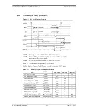
...specifications. Table 3-13 I /O Read Timing Diagram Interface Description NOTE 1: NOTE 2: NOTE 3: All timings are measured at the CompactFlash Memory Card. Skews and delays from -IORD td (IORD) th (IORD) tw (IORD) tsuA(IORD) thA(IORD) tsuCE(IORD) thCE(...20 5 0 0 --- Max. (ns) 100 45a 45a © 2007 SanDisk Corporation 3-15 Rev. 12.0, 02/07 D[15::0] signifies data provided by the system design. NOTE: SanDisk CompactFlash Memory cards do ont assert a -WAIT signal. SanDisk CompactFlash Card OEM Product Manual 3.3.8 I/O Read (Input) Timing Specification Figure 3-5 I /O ...
...specifications. Table 3-13 I /O Read Timing Diagram Interface Description NOTE 1: NOTE 2: NOTE 3: All timings are measured at the CompactFlash Memory Card. Skews and delays from -IORD td (IORD) th (IORD) tw (IORD) tsuA(IORD) thA(IORD) tsuCE(IORD) thCE(...20 5 0 0 --- Max. (ns) 100 45a 45a © 2007 SanDisk Corporation 3-15 Rev. 12.0, 02/07 D[15::0] signifies data provided by the system design. NOTE: SanDisk CompactFlash Memory cards do ont assert a -WAIT signal. SanDisk CompactFlash Card OEM Product Manual 3.3.8 I/O Read (Input) Timing Specification Figure 3-5 I /O ...


