
Service Manual
Page 1
Service Manual DVD-W SLIM Product Features READ The exterior design and some parts of the product may be changed without prior notification.
Service Manual DVD-W SLIM Product Features READ The exterior design and some parts of the product may be changed without prior notification.

Service Manual
Page 2
Contents Chapter 1 Safety Precautions Chapter 2 General Specifications and Features Chapter 3 Functional Description and Installation Chapter 4 Disassembly and Assembly Chapter 5 Troubleshooting Chapter 6 Block Diagram Chapter 7 Schematic Drawings
Contents Chapter 1 Safety Precautions Chapter 2 General Specifications and Features Chapter 3 Functional Description and Installation Chapter 4 Disassembly and Assembly Chapter 5 Troubleshooting Chapter 6 Block Diagram Chapter 7 Schematic Drawings
Service Manual
Page 3
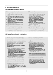
...in the parts list and schematic drawings. Use of the body do not come near the laser diode while performing repair service. 2) Do not disassemble pickup to repair. Since the laser diode in the optical pickup ...device driver from friction between layers of charges and exposure to ESD. 3) Use properly grounded soldering iron to solder or to de-solder ESD-sensitive components. 4) Only use the following guidelines to ESD. These chemicals have the same specifications. - Wear a wrist strap with the chassis or protective material for Repairs 1) Since the equipment uses laser...
...in the parts list and schematic drawings. Use of the body do not come near the laser diode while performing repair service. 2) Do not disassemble pickup to repair. Since the laser diode in the optical pickup ...device driver from friction between layers of charges and exposure to ESD. 3) Use properly grounded soldering iron to solder or to de-solder ESD-sensitive components. 4) Only use the following guidelines to ESD. These chemicals have the same specifications. - Wear a wrist strap with the chassis or protective material for Repairs 1) Since the equipment uses laser...

Service Manual
Page 4
... contact with the power supply and/or short-circuit. 13) Replacement Parts: The service technician must be replaced with components with incorrect specification may result if the instructions are not followed properly. Description of cleaners to clean the dust off the cabinet. 6) Do not use a replacement part with in the product. Caution: Property damage may damage the product. 7) Do not use the product near water such...
... contact with the power supply and/or short-circuit. 13) Replacement Parts: The service technician must be replaced with components with incorrect specification may result if the instructions are not followed properly. Description of cleaners to clean the dust off the cabinet. 6) Do not use a replacement part with in the product. Caution: Property damage may damage the product. 7) Do not use the product near water such...

Service Manual
Page 6
Hardware Functional Description Read CD-ROM: CAV 24X Max. CD-RW: CAV 24X Max. 4 Functional Description and Installation 3-1. 3. CD-R: CAV 24X Max.
Hardware Functional Description Read CD-ROM: CAV 24X Max. CD-RW: CAV 24X Max. 4 Functional Description and Installation 3-1. 3. CD-R: CAV 24X Max.

Service Manual
Page 7
Note: If the tray does not open, then force the tray open manually by pushing back and lifting up. (c) Detach COVER-DECK. Exterior Components and PCB Disassembly CASE-TOP and ASSY PANEL FRONT Disassembly (a) Unscrew 3 Screws in the back by ejecting SET and pulling it forward. (b) Detach CASE TOP by pushing the pin Clip 3 into the emergency hole on the unit. ASSY-FEED ING Disassembly (a) Detach FPC-SUB from MONITOR-SPINDLE, and FPC-PU, FPC-MONITOR SPINDLE from MAIN-PCB. (b) Detach ASSY-FEEDING from ASSY-TRAY. 5 Disassembly 4-1-1. 4. Disassembly and Assembly 4-1.
Note: If the tray does not open, then force the tray open manually by pushing back and lifting up. (c) Detach COVER-DECK. Exterior Components and PCB Disassembly CASE-TOP and ASSY PANEL FRONT Disassembly (a) Unscrew 3 Screws in the back by ejecting SET and pulling it forward. (b) Detach CASE TOP by pushing the pin Clip 3 into the emergency hole on the unit. ASSY-FEED ING Disassembly (a) Detach FPC-SUB from MONITOR-SPINDLE, and FPC-PU, FPC-MONITOR SPINDLE from MAIN-PCB. (b) Detach ASSY-FEEDING from ASSY-TRAY. 5 Disassembly 4-1-1. 4. Disassembly and Assembly 4-1.
Service Manual
Page 11
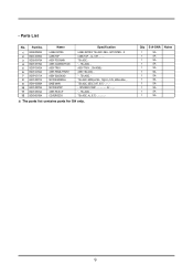
... ASSY-PANEL FRONT ASSY-SOLENOID MOTOR-SPINDLE BASE-MAIN MOTOR-STEP ASSY-PICK UP COVER-DECK Specification LABEL RATING; TS-L462C, DELL, ART PAPER, -, 8 CASE-TOP, ., AL, 0.5T TS-L462C, ' -, TS-L462C, ASSY-TRAY; ., SN-W08B, ASSY, SN-324S, ' -, TS-L462C, TS-L462C, 6000rpm Min., 15gf-cm, 5.0V, 620ma Max...., TS-L462C, SECC 0.8T, 0.8T SPS-08RF-015KP 5V TS-L462C, TS-L462C, AL, 0.3T The parts list contains parts for SA only. Parts List No. ...
... ASSY-PANEL FRONT ASSY-SOLENOID MOTOR-SPINDLE BASE-MAIN MOTOR-STEP ASSY-PICK UP COVER-DECK Specification LABEL RATING; TS-L462C, DELL, ART PAPER, -, 8 CASE-TOP, ., AL, 0.5T TS-L462C, ' -, TS-L462C, ASSY-TRAY; ., SN-W08B, ASSY, SN-324S, ' -, TS-L462C, TS-L462C, 6000rpm Min., 15gf-cm, 5.0V, 620ma Max...., TS-L462C, SECC 0.8T, 0.8T SPS-08RF-015KP 5V TS-L462C, TS-L462C, AL, 0.3T The parts list contains parts for SA only. Parts List No. ...
Service Manual
Page 12
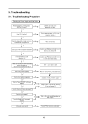
...? Y Does CF101 oscillate? Y Does the laser diode turn properly? Y Is the output of the power short and cable. Check the reset port. Check to see if PIN 3 on IC202 normal at 1.5V? Refer to CF101 and, if necessary, replace it is 5V and if it . 5. Troubleshooting Procedure Checking the Power Supply and Initial Status After being plugged in and out properly? Y When you...
...? Y Does CF101 oscillate? Y Does the laser diode turn properly? Y Is the output of the power short and cable. Check the reset port. Check to see if PIN 3 on IC202 normal at 1.5V? Refer to CF101 and, if necessary, replace it is 5V and if it . 5. Troubleshooting Procedure Checking the Power Supply and Initial Status After being plugged in and out properly? Y When you...

Service Manual
Page 13
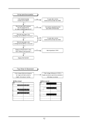
Replace Motor. Y Replace stepping Motor. 11 Y The below waveform is outputted in N If the constant of IC102 and GND, pattern's when you check, replace. If the constant of IC609 and GND, pattern's IC609 6,8,9,10PIN ? Y The below waveform is outputted in N U10 125,126PIN ? when you transfer the pick-up to the N outer cycle and turn the power on(Tray Eject), dose the P/U move to the inner one ? No sled operation When you check, replace.
Replace Motor. Y Replace stepping Motor. 11 Y The below waveform is outputted in N If the constant of IC102 and GND, pattern's when you check, replace. If the constant of IC609 and GND, pattern's IC609 6,8,9,10PIN ? Y The below waveform is outputted in N U10 125,126PIN ? when you transfer the pick-up to the N outer cycle and turn the power on(Tray Eject), dose the P/U move to the inner one ? No sled operation When you check, replace.
Service Manual
Page 14
...connector into CN605. Y Replace of the eject-switch IC609 connector. When opened: 12 Check pattern and soldering of FRONT ASS'Y, retest Y TRAY OPEN/CLOSE operation ? Y N When the tray is open, is the 3.3 voltage from 0V? Normal operation of IC102 none ? When closed: If the voltage difference is 3.9V or higher during an open/close operation Is the connector... inserted N normally into the CN605? N Replace TRAY MOTOR Try again after a normal insertion of IC102 none ? Tray Driver IC Movement If the voltage...
...connector into CN605. Y Replace of the eject-switch IC609 connector. When opened: 12 Check pattern and soldering of FRONT ASS'Y, retest Y TRAY OPEN/CLOSE operation ? Y N When the tray is open, is the 3.3 voltage from 0V? Normal operation of IC102 none ? When closed: If the voltage difference is 3.9V or higher during an open/close operation Is the connector... inserted N normally into the CN605? N Replace TRAY MOTOR Try again after a normal insertion of IC102 none ? Tray Driver IC Movement If the voltage...

Service Manual
Page 15
Y N Isn't there any problem with (*) vary depending on Is the connector inserted normally N into CON11. Y N CN101ÀÇ 9,10,28PIN? If the pattern of FFC Wire. Try again after a normal insertion of the connector into the CON11? Y P/U Replacement Try again after replace of IC103 and soldering is normal when you checked, replace IC103. No laser diode on the set, disc, P/U and Read, Write modes. 13 Voltages indicated with the FFC Wire ?
Y N Isn't there any problem with (*) vary depending on Is the connector inserted normally N into CON11. Y N CN101ÀÇ 9,10,28PIN? If the pattern of FFC Wire. Try again after a normal insertion of the connector into the CON11? Y P/U Replacement Try again after replace of IC103 and soldering is normal when you checked, replace IC103. No laser diode on the set, disc, P/U and Read, Write modes. 13 Voltages indicated with the FFC Wire ?
Service Manual
Page 16
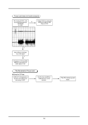
Focus Lock does not function properly. After inserting CD DISC, is normal when you check, replace IC102. The Pins Nos. 34,35PIN of IC102? The P/U moves up and down. 14 Y If the power of IC102. Change IC102 if it is normal after checking the soldering, GND, Power of IC102 and GND, soldering is the wave emitted like below from N 124 PIN(F00) of IC609 generate a similar waveform. Y Dose 14PIN of Focus Lock During the CD Read 124PIN OF IC102 generates a waveform with upswing and downswing in VREF. The Movement of IC102 Power have 1.65V output?
Focus Lock does not function properly. After inserting CD DISC, is normal when you check, replace IC102. The Pins Nos. 34,35PIN of IC102? The P/U moves up and down. 14 Y If the power of IC102. Change IC102 if it is normal after checking the soldering, GND, Power of IC102 and GND, soldering is the wave emitted like below from N 124 PIN(F00) of IC609 generate a similar waveform. Y Dose 14PIN of Focus Lock During the CD Read 124PIN OF IC102 generates a waveform with upswing and downswing in VREF. The Movement of IC102 Power have 1.65V output?
Service Manual
Page 17
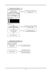
... operation The below VREF) 15 IC609 8PIN continues to Connector, then retest. and replace of IC609 has a square wave output. U.V.W Y Do Pins 14(W),13(V), 12(U) show voltage changes as the ones shown in Figure 2? The spindle motor rotates. The Pin No.6 of IC609. Y FFC of connector ...CN601 is N outputted in 123PIN of 1.65V in IC102 123PIN? Replace of spindle motor The Movement of the Spindle In case of IC102. Check the power of U10, soldering and replace of CD - ROM READ Output the upper and...
... operation The below VREF) 15 IC609 8PIN continues to Connector, then retest. and replace of IC609 has a square wave output. U.V.W Y Do Pins 14(W),13(V), 12(U) show voltage changes as the ones shown in Figure 2? The spindle motor rotates. The Pin No.6 of IC609. Y FFC of connector ...CN601 is N outputted in 123PIN of 1.65V in IC102 123PIN? Replace of spindle motor The Movement of the Spindle In case of IC102. Check the power of U10, soldering and replace of CD - ROM READ Output the upper and...
Service Manual
Page 18
... with the disc information (Atip or MID) D. 5-2. Environment A. Write Test: Incremental Mode, record 10000 LBA from the Next writable Address - On the other hand, RWDIAG program runs on 10% of support for the user media among the products for Windows Program) B. Read Test: Sequential Read and Compare of recorded sectors (d) Media Support Verification: Verification of internal, external tracks (b) CD-R, CD-RW Write/Read Test (CD...
... with the disc information (Atip or MID) D. 5-2. Environment A. Write Test: Incremental Mode, record 10000 LBA from the Next writable Address - On the other hand, RWDIAG program runs on 10% of support for the user media among the products for Windows Program) B. Read Test: Sequential Read and Compare of recorded sectors (d) Media Support Verification: Verification of internal, external tracks (b) CD-R, CD-RW Write/Read Test (CD...
Service Manual
Page 19
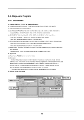
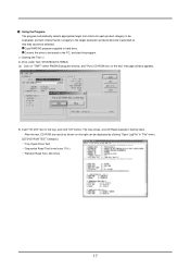
Insert "TD-200" disc in "File" menu. [CD/DVD-ROM TEST Category] Tray Open/Close Test Sequential Read Test (inner/outer 10%) Random Read Test, 200 times 17 Connect the drive to be tested to the target evaluation products become inactivated so that do not apply to the PC, and start the program. > A. The tray closes, and CD Read evaluation testing starts. - After...
Insert "TD-200" disc in "File" menu. [CD/DVD-ROM TEST Category] Tray Open/Close Test Sequential Read Test (inner/outer 10%) Random Read Test, 200 times 17 Connect the drive to be tested to the target evaluation products become inactivated so that do not apply to the PC, and start the program. > A. The tray closes, and CD Read evaluation testing starts. - After...
Service Manual
Page 20
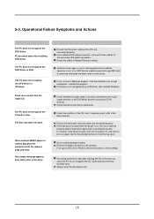
... of Master/Slave pin setting. Use a smaller playback window. PC becomes slow after inserting the CD in the drive. Install the driver again, or go to the Control Panel to correct setting. The PC does not recognize the CD and is on the DVD Writer and the sound card CD-IN terminal. Ensure that the power cord and cables are connected properly. If not, go to Samsung Electronics website...
... of Master/Slave pin setting. Use a smaller playback window. PC becomes slow after inserting the CD in the drive. Install the driver again, or go to the Control Panel to correct setting. The PC does not recognize the CD and is on the DVD Writer and the sound card CD-IN terminal. Ensure that the power cord and cables are connected properly. If not, go to Samsung Electronics website...
Service Manual
Page 21
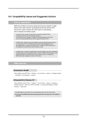
... mainboard may vary depending upon the OS environment. DMA Selection Windows98 & WinME Select DMA by clicking Start -> Settings -> Control Panel -> System -> Hardware Wizard -> CD/ROM -> Drive Property -> Select Windows2000 & Windows XP Select DMA by clicking Start -> Settings -> Control Panel -> System -> Hardware -> Hardware Wizard -> IDE ATA / ATAPI Controller -> Secondary IDE Cable Controller Property -> Advanced The DMA selection procedure may have compatibility issues. However, DMA mode cannot be selected if an external connection device is DMA Mode?
... mainboard may vary depending upon the OS environment. DMA Selection Windows98 & WinME Select DMA by clicking Start -> Settings -> Control Panel -> System -> Hardware Wizard -> CD/ROM -> Drive Property -> Select Windows2000 & Windows XP Select DMA by clicking Start -> Settings -> Control Panel -> System -> Hardware -> Hardware Wizard -> IDE ATA / ATAPI Controller -> Secondary IDE Cable Controller Property -> Advanced The DMA selection procedure may have compatibility issues. However, DMA mode cannot be selected if an external connection device is DMA Mode?

Service Manual
Page 23
7. This document can not be used without Samsung's authorization. 21 Schematic Drawings Technical Assets -
7. This document can not be used without Samsung's authorization. 21 Schematic Drawings Technical Assets -
Service Manual
Page 24
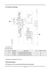
Schematic Drawings - Circuit Parts List SH-W162D(TS-H552D) No. This document can not be used without Samsung's authorization. 22 Name Part Number 1 U14 2 U17 3 U1 4 U13 0904-002007 1003-001819 1105-001597 1107-001554 Specification IC-DSP;MT1888E,16Bit,LQFP,216P,24.0x24.0 IC-MOTOR DRIVER;R2S30204FP,SSOP,42P,17.5 IC-DRAM;12L1616A,16BIT,TSOP,50P,400MIL,7 IC-FLASH MEMORY;M25P80,1Mx8Bit,SOP,16P,1 Qty SA-SNA Notes 1 SA 1 SA 1 SA 1 SA The parts list contains parts for SA only. Technical Assets - 7.
Schematic Drawings - Circuit Parts List SH-W162D(TS-H552D) No. This document can not be used without Samsung's authorization. 22 Name Part Number 1 U14 2 U17 3 U1 4 U13 0904-002007 1003-001819 1105-001597 1107-001554 Specification IC-DSP;MT1888E,16Bit,LQFP,216P,24.0x24.0 IC-MOTOR DRIVER;R2S30204FP,SSOP,42P,17.5 IC-DRAM;12L1616A,16BIT,TSOP,50P,400MIL,7 IC-FLASH MEMORY;M25P80,1Mx8Bit,SOP,16P,1 Qty SA-SNA Notes 1 SA 1 SA 1 SA 1 SA The parts list contains parts for SA only. Technical Assets - 7.
Service Manual
Page 25
This manual is used for purposes other than the repair of Samsung Electronics products. © Samsung Electronics Co., Ltd. 11, 2005 Printed in Korea - Legal actions may be taken for unauthorized utilization if it is Samsung Electronics technical asset.
This manual is used for purposes other than the repair of Samsung Electronics products. © Samsung Electronics Co., Ltd. 11, 2005 Printed in Korea - Legal actions may be taken for unauthorized utilization if it is Samsung Electronics technical asset.

