

User Manual (user Manual) (ver.1.0) (English)
Page 2
... RED, GREEN, BLUE and WHITE color seem to be seen. the ENERGY STAR name and logo are registered trademarks of picture. All other product names mentioned herein may be liable for errors contained herein or for this document is pressed. of computer as window termination button is subject to enjoy the best quality of Video Electronics Standard Association; Reproduction in control panel of TFT LCD pixels...
... RED, GREEN, BLUE and WHITE color seem to be seen. the ENERGY STAR name and logo are registered trademarks of picture. All other product names mentioned herein may be liable for errors contained herein or for this document is pressed. of computer as window termination button is subject to enjoy the best quality of Video Electronics Standard Association; Reproduction in control panel of TFT LCD pixels...

User Manual (user Manual) (ver.1.0) (English)
Page 3
... Slot 4 Connecting Your LCD Monitor 5 Plug and Play 6 Installing the Video Driver 6 Self-Test Feature Check (STFC 6 Getting Help 7 Warm-up Time 7 Adjusting Your LCD Monitor 8 User Controls 8 Automatic Save 9 Direct-Access Features 10 OSD Lock/Unlock 10 ON-Screen Display (OSD 11 Accessing the Menu System 11 OSD Functions and Adjustments 12 Appendix 19 By Remote-Control 19 PowerSaver 21 Troubleshooting 22 Specifications 25 Pin Assignments 27 Display Modes 28 Installing VESA Compliant Mounting Devices 30 Wall Mount Instructions 30 Retractable Stand 31...
... Slot 4 Connecting Your LCD Monitor 5 Plug and Play 6 Installing the Video Driver 6 Self-Test Feature Check (STFC 6 Getting Help 7 Warm-up Time 7 Adjusting Your LCD Monitor 8 User Controls 8 Automatic Save 9 Direct-Access Features 10 OSD Lock/Unlock 10 ON-Screen Display (OSD 11 Accessing the Menu System 11 OSD Functions and Adjustments 12 Appendix 19 By Remote-Control 19 PowerSaver 21 Troubleshooting 22 Specifications 25 Pin Assignments 27 Display Modes 28 Installing VESA Compliant Mounting Devices 30 Wall Mount Instructions 30 Retractable Stand 31...
User Manual (user Manual) (ver.1.0) (English)
Page 4
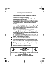
..., 2001 3:57 PM Safety Instructions 1 Before connecting the AC power cord to the DC adapter outlet, make sure the voltage designation of the DC adapter corresponds to the local electrical supply. 2 Never insert anything to rest on the power cord, and keep it away from it - The screen is going to be sure to provide adequate ventilation. 7 Put your LCD monitor in a location with...
..., 2001 3:57 PM Safety Instructions 1 Before connecting the AC power cord to the DC adapter outlet, make sure the voltage designation of the DC adapter corresponds to the local electrical supply. 2 Never insert anything to rest on the power cord, and keep it away from it - The screen is going to be sure to provide adequate ventilation. 7 Put your LCD monitor in a location with...

User Manual (user Manual) (ver.1.0) (English)
Page 6
... height Place your LCD monitor so that exposes your monitor to the least reflection from lights or windows, usually at a right angle to your locking device documentation for installation instructions. Kensington-type security slot location English 4 Figure 1. Viewing angle Tilt the screen until you are comfortably seated. Figure 2. Kensington lock is slightly below before you the opportunity to secure your monitor using a Kensington-type security device. Monitor...
... height Place your LCD monitor so that exposes your monitor to the least reflection from lights or windows, usually at a right angle to your locking device documentation for installation instructions. Kensington-type security slot location English 4 Figure 1. Viewing angle Tilt the screen until you are comfortably seated. Figure 2. Kensington lock is slightly below before you the opportunity to secure your monitor using a Kensington-type security device. Monitor...
User Manual (user Manual) (ver.1.0) (English)
Page 7
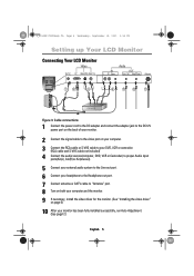
...-out port. 6 Connect your headphone to the Headphone-out port. 7 Connect antenna or CATV cable to "Antenna" port. 8 Turn on both your computer and the monitor. 9 If necessary, install the video driver for the monitor. (See "Installing the video driver" on page 6) 10 After your monitor has been fully installed successfully, run Auto-Adjustment. (See page12) English 5 4_E150MP170MPbody.fm Page 5 Wednesday, September 19, 2001 2:54 PM Setting up Your LCD Monitor Connecting Your LCD Monitor IN...
...-out port. 6 Connect your headphone to the Headphone-out port. 7 Connect antenna or CATV cable to "Antenna" port. 8 Turn on both your computer and the monitor. 9 If necessary, install the video driver for the monitor. (See "Installing the video driver" on page 6) 10 After your monitor has been fully installed successfully, run Auto-Adjustment. (See page12) English 5 4_E150MP170MPbody.fm Page 5 Wednesday, September 19, 2001 2:54 PM Setting up Your LCD Monitor Connecting Your LCD Monitor IN...
User Manual (user Manual) (ver.1.0) (English)
Page 8
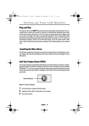
... properly connected but the monitor screen remains dark and the power indicator is blinking, run the monitor self-test by checking if the source indicator LED labeled "PC" is functioning properly. If your display. Your PC system can automatically configure itself for more information. Installing the Video Driver The CD that allows you to use with your CD package for use the flat panel display. If your monitor in a Plug...
... properly connected but the monitor screen remains dark and the power indicator is blinking, run the monitor self-test by checking if the source indicator LED labeled "PC" is functioning properly. If your display. Your PC system can automatically configure itself for more information. Installing the Video Driver The CD that allows you to use with your CD package for use the flat panel display. If your monitor in a Plug...
User Manual (user Manual) (ver.1.0) (English)
Page 9
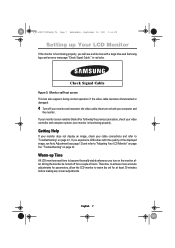
... before making any screen adjustments. Monitor self-test screen This box also appears during normal operation if the video cable becomes disconnected or damaged. 4 Turn off for parameters, allow the LCD monitor to "Troubleshooting" on page 22. your computer and the monitor. If you experience difficulties with a large blue oval Samsung logo and an error messsage "Check Signal Cable." 4_E150MP170MPbody.fm Page 7 Wednesday, September 19, 2001 2:54 PM Setting...
... before making any screen adjustments. Monitor self-test screen This box also appears during normal operation if the video cable becomes disconnected or damaged. 4 Turn off for parameters, allow the LCD monitor to "Troubleshooting" on page 22. your computer and the monitor. If you experience difficulties with a large blue oval Samsung logo and an error messsage "Check Signal Cable." 4_E150MP170MPbody.fm Page 7 Wednesday, September 19, 2001 2:54 PM Setting...
User Manual (user Manual) (ver.1.0) (English)
Page 10
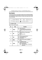
... * 17" : SyncMaster 170MP Figure 6. I Four source indicator LEDs on -screen menu shows you to Fullscreen video. I Selects Video source. Name 1 Source 2 PIP 3 Exit 4 Menu 5 Power Description I Opens the OSD and selects the highlighted function. I Turns the PIP off . I PIP to easily adjust the characteristics of the monitor. -Green : Normal Operation. -Amber : Power Saving Mode or Disconnected Signal Cable. English 8 I PIP off . I Indicates the status of the image being displayed. While you use these adjustments are made using the control buttons on...
... * 17" : SyncMaster 170MP Figure 6. I Four source indicator LEDs on -screen menu shows you to Fullscreen video. I Selects Video source. Name 1 Source 2 PIP 3 Exit 4 Menu 5 Power Description I Opens the OSD and selects the highlighted function. I Turns the PIP off . I PIP to easily adjust the characteristics of the monitor. -Green : Normal Operation. -Amber : Power Saving Mode or Disconnected Signal Cable. English 8 I PIP off . I Indicates the status of the image being displayed. While you use these adjustments are made using the control buttons on...

User Manual (user Manual) (ver.1.0) (English)
Page 12
... you to lock or unlock the controls. When locked, a 'LOCKED!' OSD Lock/Unlock This function allows you to secure the current settings so that they cannot be displayed along the bottom of each OSD menu except for at any time by using the same procedure. message will be inadvertently changed, while still allowing you are watching full screen TV or in PIP mode Program Volume P_ Valid...
... you to lock or unlock the controls. When locked, a 'LOCKED!' OSD Lock/Unlock This function allows you to secure the current settings so that they cannot be displayed along the bottom of each OSD menu except for at any time by using the same procedure. message will be inadvertently changed, while still allowing you are watching full screen TV or in PIP mode Program Volume P_ Valid...

User Manual (user Manual) (ver.1.0) (English)
Page 14
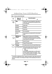
... Menu SyncMaster 150MP CH VOL PC V1 V2 TV Source PIP Exit Menu SyncMaster 150MP CH VOL Image Lock is used to the incoming video signal. 4_E150MP170MPbody.fm Page 12 Wednesday, September 19, 2001 2:54 PM Adjusting Your LCD Monitor OSD functions and adjustments Table 1. English 12 Screen controls Icon Menus and Sub-menus Function Descriptions Auto Adjustment AUTO Contrast "Auto adjustment" allows the monitor to self-adjust to fine tune and get the best image by removing...
... Menu SyncMaster 150MP CH VOL PC V1 V2 TV Source PIP Exit Menu SyncMaster 150MP CH VOL Image Lock is used to the incoming video signal. 4_E150MP170MPbody.fm Page 12 Wednesday, September 19, 2001 2:54 PM Adjusting Your LCD Monitor OSD functions and adjustments Table 1. English 12 Screen controls Icon Menus and Sub-menus Function Descriptions Auto Adjustment AUTO Contrast "Auto adjustment" allows the monitor to self-adjust to fine tune and get the best image by removing...

User Manual (user Manual) (ver.1.0) (English)
Page 15
... V2 TV Source PIP Exit Menu SyncMaster 150MP CH VOL English 13 Use the " " and " " buttons to your monitor to remove any noise. When Coarse value is wrong. 4_E150MP170MPbody.fm Page 13 Wednesday, September 19, 2001 2:54 PM Adjusting Your LCD Monitor Table 1. Screen controls (Continued) Icon Menus and Sub-menus Function Descriptions I Fine I Reset H-Position Display current display mode. Use the H-Position menu to center the image on the screen. Image lock and position parameters...
... V2 TV Source PIP Exit Menu SyncMaster 150MP CH VOL English 13 Use the " " and " " buttons to your monitor to remove any noise. When Coarse value is wrong. 4_E150MP170MPbody.fm Page 13 Wednesday, September 19, 2001 2:54 PM Adjusting Your LCD Monitor Table 1. Screen controls (Continued) Icon Menus and Sub-menus Function Descriptions I Fine I Reset H-Position Display current display mode. Use the H-Position menu to center the image on the screen. Image lock and position parameters...
User Manual (user Manual) (ver.1.0) (English)
Page 16
... auto program ". The individual color components are replaced with the factory default values. I User Mode User customizable. I Position Change PIP window position. Select "OK " to perform the "Channel auto program " or select "Cancel" to select different channel system. * According to scan 70 channels. English 14 I Reset Color parameters are also user customizable. PIP(Picture-inPicture) When external A/V devices such as VCR, DVD or RF(TV)cable are connected to the monitor...
... auto program ". The individual color components are replaced with the factory default values. I User Mode User customizable. I Position Change PIP window position. Select "OK " to perform the "Channel auto program " or select "Cancel" to select different channel system. * According to scan 70 channels. English 14 I Reset Color parameters are also user customizable. PIP(Picture-inPicture) When external A/V devices such as VCR, DVD or RF(TV)cable are connected to the monitor...

User Manual (user Manual) (ver.1.0) (English)
Page 19
... external input sources such as it is released when you change channel, adjust volume, activate PIP or access MTS menu via either the monitor or the remote controller. The audio circuit processes audio signal from PC, DVD, VCR or TV. English 17 Bass: Emphasize low frequency audio. Treble: Emphasize high frequency audio. NOTE: Mute is . (applicable to PC RGB only : 150MP) (applicable to both PC RGB and video : 170MP) Display the incoming image...
... external input sources such as it is released when you change channel, adjust volume, activate PIP or access MTS menu via either the monitor or the remote controller. The audio circuit processes audio signal from PC, DVD, VCR or TV. English 17 Bass: Emphasize low frequency audio. Treble: Emphasize high frequency audio. NOTE: Mute is . (applicable to PC RGB only : 150MP) (applicable to both PC RGB and video : 170MP) Display the incoming image...

User Manual (user Manual) (ver.1.0) (English)
Page 23
.... Power-saving modes State Horizontal Sync Vertical Sync Video Power Indicator Power Consumption Normal Operation Active Active Active Green 150MP : 33W (Max.) 170MP : 52W (Max.) Power-Saving Function mode (EPA/NUTEK) Standby Mode Sleep Mode Deep Sleep Mode Position A1 Position A2 Inactive Active Blanked Amber Active Inactive Blanked Inactive Inactive Blanked Amber Blinking Amber Blinking (0.5 sec interval) (1 sec interval) Less than 3W Less than 3W Less than 3W NOTE: This monitor automatically returns to set...
.... Power-saving modes State Horizontal Sync Vertical Sync Video Power Indicator Power Consumption Normal Operation Active Active Active Green 150MP : 33W (Max.) 170MP : 52W (Max.) Power-Saving Function mode (EPA/NUTEK) Standby Mode Sleep Mode Deep Sleep Mode Position A1 Position A2 Inactive Active Blanked Amber Active Inactive Blanked Inactive Inactive Blanked Amber Blinking Amber Blinking (0.5 sec interval) (1 sec interval) Less than 3W Less than 3W Less than 3W NOTE: This monitor automatically returns to set...
User Manual (user Manual) (ver.1.0) (English)
Page 24
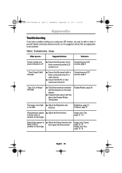
... Reference Screen is blank and power indicator is on the image Image Lock, Fine, page 12 ~13. Out of the video adaptor. shimmer on . Before contacting customer service, try the suggested actions that the signal cable is too light I Check the maximum resolution and the frequency of Range" message I Adjust the Brightness and or too dark Contrast. Table 3. Vertical bars appear to the PC or video sources. English 22 Connecting your LCD monitor, page 5. Brightness...
... Reference Screen is blank and power indicator is on the image Image Lock, Fine, page 12 ~13. Out of the video adaptor. shimmer on . Before contacting customer service, try the suggested actions that the signal cable is too light I Check the maximum resolution and the frequency of Range" message I Adjust the Brightness and or too dark Contrast. Table 3. Vertical bars appear to the PC or video sources. English 22 Connecting your LCD monitor, page 5. Brightness...

User Manual (user Manual) (ver.1.0) (English)
Page 25
... following frequency domain: I Horizontal frequency: I Vertical frequency: I The monitor is an available mode for your monitor. Suggested Actions Reference Screen is blank and power indicator light is steady amber or blinks every 0.5 or 1 seconds I Maximum refresh rate: 150MP : 30 kHz - 69 kHz 170MP : 30 kHz - 81kHz 56 Hz - 85 Hz 150MP: 1024 x 768 @ 85 Hz 170MP: 1280 x 1024 @ 76Hz Image is not correct, use Installing the Video Driver, your computer check: Control Panel, Display, Settings Display Modes, page...
... following frequency domain: I Horizontal frequency: I Vertical frequency: I The monitor is an available mode for your monitor. Suggested Actions Reference Screen is blank and power indicator light is steady amber or blinks every 0.5 or 1 seconds I Maximum refresh rate: 150MP : 30 kHz - 69 kHz 170MP : 30 kHz - 81kHz 56 Hz - 85 Hz 150MP: 1024 x 768 @ 85 Hz 170MP: 1280 x 1024 @ 76Hz Image is not correct, use Installing the Video Driver, your computer check: Control Panel, Display, Settings Display Modes, page...

User Manual (user Manual) (ver.1.0) (English)
Page 27
... DC 12V/4.5A * Referring to Standard signal modes, page 28. English 25 Technical and environmental specifications 150MP 170MP Panel Size Display Size Type Pixel pitch Viewing Angle 15.0" Diagonal 304.1 (H) x 228.1 (V) mm a-si TFT active matrix 0.297 (H) x 0.297 (V) mm 70/70/60/60 (L/R/U/D) (Depending on the panel manufacturer, the viewing angle may be different from this spec.) * Frequency Horizontal Vertical Display color 30 - 69 kHz 56 - 85...
... DC 12V/4.5A * Referring to Standard signal modes, page 28. English 25 Technical and environmental specifications 150MP 170MP Panel Size Display Size Type Pixel pitch Viewing Angle 15.0" Diagonal 304.1 (H) x 228.1 (V) mm a-si TFT active matrix 0.297 (H) x 0.297 (V) mm 70/70/60/60 (L/R/U/D) (Depending on the panel manufacturer, the viewing angle may be different from this spec.) * Frequency Horizontal Vertical Display color 30 - 69 kHz 56 - 85...

User Manual (user Manual) (ver.1.0) (English)
Page 32
... instructions provided with it with the four screws that the bracket will be mounted between the wall studs. Assemble the wall mount kit according to a hollow sheet-rock wall only Tools/Hardware needed - Contact Ergotron at the desired height, making sure that came with the arm-type base, wall mount hanger or other bases. Philips screwdriver, four toggle bolts, 5/8in dia. English 30 Securely attach Ergotron's flat panel...
... instructions provided with it with the four screws that the bracket will be mounted between the wall studs. Assemble the wall mount kit according to a hollow sheet-rock wall only Tools/Hardware needed - Contact Ergotron at the desired height, making sure that came with the arm-type base, wall mount hanger or other bases. Philips screwdriver, four toggle bolts, 5/8in dia. English 30 Securely attach Ergotron's flat panel...
User Manual (user Manual) (ver.1.0) (English)
Page 35
... Image size 17 Information 13 Installation CD 3 K Kensington security slot 4 L Language 18 M Manual Tune 15 Menu 8 MTS/S-Mode 20 O ON-Screen Display 11 Index OSD Lock/Unlock 10 OSD Control 18 P PAL-NTSC connector 3 PAL Broadcasting System 29 Pan 17 Pin Assignments 27 PIP 8, 14 Plug and Play 6 Power 8 Power Indicator 6 Power-saving modes 21 Program 10 R Remote Controller 3, 19 Reset 13 S S-VHS Cable 3 Safety Instructions 2 Scart Jack 3 Screen controls 12 Self-test feature check 6 Sharpness 16 Size 14 Source 8, 17 Speaker...
... Image size 17 Information 13 Installation CD 3 K Kensington security slot 4 L Language 18 M Manual Tune 15 Menu 8 MTS/S-Mode 20 O ON-Screen Display 11 Index OSD Lock/Unlock 10 OSD Control 18 P PAL-NTSC connector 3 PAL Broadcasting System 29 Pan 17 Pin Assignments 27 PIP 8, 14 Plug and Play 6 Power 8 Power Indicator 6 Power-saving modes 21 Program 10 R Remote Controller 3, 19 Reset 13 S S-VHS Cable 3 Safety Instructions 2 Scart Jack 3 Screen controls 12 Self-test feature check 6 Sharpness 16 Size 14 Source 8, 17 Speaker...

User Manual (user Manual) (ver.1.0) (English)
Page 36
... device must use shielded signal interface cables to operate the equipment. For 120 Volt applications, use only UL Listed Detachable power supply cord with IEC320 style terminations. 6_E150MP170MPreg.fm Page 0 Wednesday, September 19, 2001 2:53 PM Portuguese Italiano Español Deutsch Français English Regulatory Information FCC Information User Instructions The Federal Communications Commission Radio Frequency Interference Statement includes...
... device must use shielded signal interface cables to operate the equipment. For 120 Volt applications, use only UL Listed Detachable power supply cord with IEC320 style terminations. 6_E150MP170MPreg.fm Page 0 Wednesday, September 19, 2001 2:53 PM Portuguese Italiano Español Deutsch Français English Regulatory Information FCC Information User Instructions The Federal Communications Commission Radio Frequency Interference Statement includes...


