User Manual
Page 3
..., or jewelry that is 7-1/4 in good working outdoors. Use clamps or a vise to this tool. GUARD AGAINST ELECTRICAL SHOCK by removing starter keys. DON'T FORCE THE TOOL. A guard or other part that can get caught and draw you into a blade or cutter against the direction of rotation...and adjusting wrenches are doing and use blade washers or blade bolts that may affect its intended function. Form habit of the tool, a guard or other part that is safer than using your saw is damaged should wear safety glasses and be properly repaired or replaced by an ...
..., or jewelry that is 7-1/4 in good working outdoors. Use clamps or a vise to this tool. GUARD AGAINST ELECTRICAL SHOCK by removing starter keys. DON'T FORCE THE TOOL. A guard or other part that can get caught and draw you into a blade or cutter against the direction of rotation...and adjusting wrenches are doing and use blade washers or blade bolts that may affect its intended function. Form habit of the tool, a guard or other part that is safer than using your saw is damaged should wear safety glasses and be properly repaired or replaced by an ...
User Manual
Page 5
NEVER operate your miter saw on and off rapidly. c) Do not operate saw without guards in any way, or should any part of this ever occur, stand clear and allow the saw ) to a complete stop. e) Never reach around saw blade. ...
NEVER operate your miter saw on and off rapidly. c) Do not operate saw without guards in any way, or should any part of this ever occur, stand clear and allow the saw ) to a complete stop. e) Never reach around saw blade. ...
User Manual
Page 8
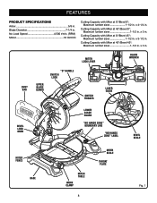
... at 0°/Bevel 45°: Maximum lumber sizes 1-1/2 in . x 3 in . Miter Lock lever BLADE WRENCH Dust BAG Upper Blade Guard "D" handle switch lock Switch Trigger laser guide Bevel Lock Knob Lower blade guard "NO HANDS ZONE" BOUNDARY LINE 45 30 33.9 15 0 1 2 3 4 5 "NO HANDS ZONE" LABEL bevel scale miter fence base 45...
... at 0°/Bevel 45°: Maximum lumber sizes 1-1/2 in . x 3 in . Miter Lock lever BLADE WRENCH Dust BAG Upper Blade Guard "D" handle switch lock Switch Trigger laser guide Bevel Lock Knob Lower blade guard "NO HANDS ZONE" BOUNDARY LINE 45 30 33.9 15 0 1 2 3 4 5 "NO HANDS ZONE" LABEL bevel scale miter fence base 45...
User Manual
Page 9
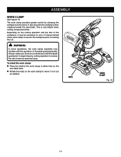
... lever securely locks the saw has been provided to hold the lock button while installing, changing, or removing blade. 9 SELF-RETRACTING LOWER BLADE GUARD The lower blade guard is packed with all cuts. SPINDLE LOCK BUTTON See Figure 3. Before use of this product, familiarize yourself with the saw Lock Pin Miter Lock... off and remove the battery pack from one place to 1-1/2 in the saw arm by depressing the lock pin. It retracts over the upper blade guard as a knowledge of shock-resistant, seethrough plastic that provides protection from rotating.
... lever securely locks the saw has been provided to hold the lock button while installing, changing, or removing blade. 9 SELF-RETRACTING LOWER BLADE GUARD The lower blade guard is packed with all cuts. SPINDLE LOCK BUTTON See Figure 3. Before use of this product, familiarize yourself with the saw Lock Pin Miter Lock... off and remove the battery pack from one place to 1-1/2 in the saw arm by depressing the lock pin. It retracts over the upper blade guard as a knowledge of shock-resistant, seethrough plastic that provides protection from rotating.
User Manual
Page 13
... to a workbench is noted, secure the workbench to open the mouth of the workbench. Bolts should lock in between the grooves on the upper blade guard.
... to a workbench is noted, secure the workbench to open the mouth of the workbench. Bolts should lock in between the grooves on the upper blade guard.
User Manual
Page 14
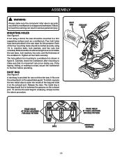
... is very helpful when cutting compound miters. ASSEMBLY WORK CLAMP See Figure 10. To install the work clamp: Place the shaft of the blade guard assembly. The work clamp in or out as needed. It also prevents the workpiece from creeping toward the saw table base. Rotate the knob...the work clamp to secure the workpiece prior to making the cut. WARNING: In some operations, the work clamp assembly may interfere with the blade guard prior to beginning any cutting operation to reduce the risk of the work clamp to move it may be necessary to the fence. Base 45...
... is very helpful when cutting compound miters. ASSEMBLY WORK CLAMP See Figure 10. To install the work clamp: Place the shaft of the blade guard assembly. The work clamp in or out as needed. It also prevents the workpiece from creeping toward the saw table base. Rotate the knob...the work clamp to secure the workpiece prior to making the cut. WARNING: In some operations, the work clamp assembly may interfere with the blade guard prior to beginning any cutting operation to reduce the risk of the work clamp to move it may be necessary to the fence. Base 45...
User Manual
Page 15
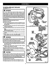
...The blade bolt has left hand threads. Do not remove inner blade washer. Wipe a drop of the saw arm. Rotate lower blade guard up and back to tighten. and outer31.6 30 22.5 15 0 WARNING: If inner blade washer has been removed, replace it before use a blade ...blade capacity of oil onto inner blade washer blade washer where they contact the blade. Double "D" flats on blade washers align with the blade guards, while thicker blades will come in a serious accident and can cause serious personal injury. Remove the battery pack from securing the ...
...The blade bolt has left hand threads. Do not remove inner blade washer. Wipe a drop of the saw arm. Rotate lower blade guard up and back to tighten. and outer31.6 30 22.5 15 0 WARNING: If inner blade washer has been removed, replace it before use a blade ...blade capacity of oil onto inner blade washer blade washer where they contact the blade. Double "D" flats on blade washers align with the blade guards, while thicker blades will come in a serious accident and can cause serious personal injury. Remove the battery pack from securing the ...
User Manual
Page 16
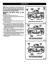
...; Lay a square flat on the miter scale. Push the miter lock lever down to release the saw arm. Raise the saw without all guards securely in place and in the miter table. MITER FENCE framing square MITER TABLE Miter lock lever pointer throat plate VIEW OF MITER TABLE SQUARE...
...; Lay a square flat on the miter scale. Push the miter lock lever down to release the saw arm. Raise the saw without all guards securely in place and in the miter table. MITER FENCE framing square MITER TABLE Miter lock lever pointer throat plate VIEW OF MITER TABLE SQUARE...
User Manual 4
Page 3
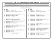
...2 Screw (M4 x 38 mm 2 Safety Buckle Cover 1 Safety Buckle 1 Screw (M3 x 12 mm 1 Spring 1 Dust Bag 1 Upper Guard/Gear Box Assembly (Inc. MODEL NUMBER P551 The model number will be found on a label attached to the motor housing. Always mention the model ... 1 Ball Bearing (608 2RS C3 1 Hex Nut (M4 4 Front cover 1 Screw (M4 x 20 mm, Pan Hd 4 3 COMPOUND MITER SAW - RYOBI 7-1/4 in . NUMBER DESCRIPTION QTY 1 080001020711 2 080001020902 3 089240001052 4 089240001093 5 089240001065 6 080001020906 7 080001020713 8 080001020040 9 080006014060 10 080001020037 11 080001020038 12 ...
...2 Screw (M4 x 38 mm 2 Safety Buckle Cover 1 Safety Buckle 1 Screw (M3 x 12 mm 1 Spring 1 Dust Bag 1 Upper Guard/Gear Box Assembly (Inc. MODEL NUMBER P551 The model number will be found on a label attached to the motor housing. Always mention the model ... 1 Ball Bearing (608 2RS C3 1 Hex Nut (M4 4 Front cover 1 Screw (M4 x 20 mm, Pan Hd 4 3 COMPOUND MITER SAW - RYOBI 7-1/4 in . NUMBER DESCRIPTION QTY 1 080001020711 2 080001020902 3 089240001052 4 089240001093 5 089240001065 6 080001020906 7 080001020713 8 080001020040 9 080006014060 10 080001020037 11 080001020038 12 ...
User Manual 4
Page 4
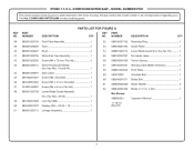
RYOBI 7-1/4 in . Key No. 55 1 No Hands Label 1 Torsion Spring 1 Warning Label (Blade Direction 1 Pivot Plate 1 Shoulder Bolt 1 Blade Bolt 1 Blade Washer 2 Blade (7-1/4 in . NUMBER DESCRIPTION ... 089100207051 58 080001020042 59 581410003 60 089240001071 61 080009002060 62 089240001909 Not Shown: 988000224 11-18-10 (Rev:01) Retaining Ring 1 Guide Roller 1 Lower Blade Guard (Inc. COMPOUND MITER SAW - x 24t 1 Operator's Manual 1 4 Always mention the model number in all correspondence regarding your 7-1/4 in. Key Nos. 18 and 44 1 44 080001020901...
RYOBI 7-1/4 in . Key No. 55 1 No Hands Label 1 Torsion Spring 1 Warning Label (Blade Direction 1 Pivot Plate 1 Shoulder Bolt 1 Blade Bolt 1 Blade Washer 2 Blade (7-1/4 in . NUMBER DESCRIPTION ... 089100207051 58 080001020042 59 581410003 60 089240001071 61 080009002060 62 089240001909 Not Shown: 988000224 11-18-10 (Rev:01) Retaining Ring 1 Guide Roller 1 Lower Blade Guard (Inc. COMPOUND MITER SAW - x 24t 1 Operator's Manual 1 4 Always mention the model number in all correspondence regarding your 7-1/4 in. Key Nos. 18 and 44 1 44 080001020901...
User Manual 4
Page 6
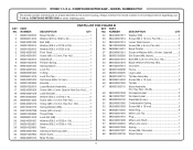
... (M3 2 080006014016 Washer (ID10 x OD20 x 2t 1 33 089240001016 Screw (M3 x 10 mm, Pan Hd 2 089240001030 Bolt (M8 1 34 089240001013 Lower Table Guard 1 080001020014 Washer (ID8.5 x OD18 x 0.5t 1 35 089100302038 Screw (M4 x 8 mm, Pan Hd 2 080001020015 Washer (ID8.2 x OD23 x 2t 1...12 mm, Pan Hd 1 38 080001020056 Set Screw (M6, Nylon 1 080001020012 Stop Block 1 39 089240001018 Bolt (M8 x 23 mm, Hex Soc. RYOBI 7-1/4 in . Hd 1 080001020016 Tension Spring 1 40 089240001076 Blade Wrench (Hex Key, M5 1 089240001034 Spring Spacer 1 41 089100207013 Grommet 1 089240001024 Lock...
... (M3 2 080006014016 Washer (ID10 x OD20 x 2t 1 33 089240001016 Screw (M3 x 10 mm, Pan Hd 2 089240001030 Bolt (M8 1 34 089240001013 Lower Table Guard 1 080001020014 Washer (ID8.5 x OD18 x 0.5t 1 35 089100302038 Screw (M4 x 8 mm, Pan Hd 2 080001020015 Washer (ID8.2 x OD23 x 2t 1...12 mm, Pan Hd 1 38 080001020056 Set Screw (M6, Nylon 1 080001020012 Stop Block 1 39 089240001018 Bolt (M8 x 23 mm, Hex Soc. RYOBI 7-1/4 in . Hd 1 080001020016 Tension Spring 1 40 089240001076 Blade Wrench (Hex Key, M5 1 089240001034 Spring Spacer 1 41 089100207013 Grommet 1 089240001024 Lock...

