
Operation Manual
Page 1
When properly cared for, it will give you for dependability, ease of operation, and operator safety. SAVE THIS MANUAL FOR FUTURE REFERENCE Compound Miter Saw TS1343L - WARNING: To reduce the risk of rugged, trouble-free performance. Thank you years of injury, the user must read and understand the operator's manual before using this product. OPERATOR'S MANUAL 10 in. Double Insulated Your miter saw has been engineered and manufactured to our high standard for your purchase.
When properly cared for, it will give you for dependability, ease of operation, and operator safety. SAVE THIS MANUAL FOR FUTURE REFERENCE Compound Miter Saw TS1343L - WARNING: To reduce the risk of rugged, trouble-free performance. Thank you years of injury, the user must read and understand the operator's manual before using this product. OPERATOR'S MANUAL 10 in. Double Insulated Your miter saw has been engineered and manufactured to our high standard for your purchase.
Operation Manual
Page 4
... BEFORE MAKING A CUT, BE SURE ALL ADJUSTMENTS ARE SECURE. BE SURE BLADE PATH IS FREE OF NAILS. Never start the saw with saw from lumber before connecting to install the proper outlet. To reduce the risk of electric shock, this manual or addendums. Use of personal injury. .... WHEN SERVICING use common sense. Repair or replace a damaged or worn cord immediately. Always use blades with your tool to prevent the saw or workpiece before cutting. NEVER TOUCH BLADE or other ). If a work or in a polarized outlet only one blade is too small ...
... BEFORE MAKING A CUT, BE SURE ALL ADJUSTMENTS ARE SECURE. BE SURE BLADE PATH IS FREE OF NAILS. Never start the saw with saw from lumber before connecting to install the proper outlet. To reduce the risk of electric shock, this manual or addendums. Use of personal injury. .... WHEN SERVICING use common sense. Repair or replace a damaged or worn cord immediately. Always use blades with your tool to prevent the saw or workpiece before cutting. NEVER TOUCH BLADE or other ). If a work or in a polarized outlet only one blade is too small ...
Operation Manual
Page 5
...replaced before raising it must be replaced only by the manufacturer or by the "D" handle. AVOID direct eye exposure when using the saw is not secured to a complete stop before moving workpiece or changing settings. THIS TOOL should any way, or should have good... balance. NEVER operate the miter saw on the floor or in contact with safe operation BEFORE performing any operation freehand. d) Do not perform any work surface. ALWAYS REMEMBER that...
...replaced before raising it must be replaced only by the manufacturer or by the "D" handle. AVOID direct eye exposure when using the saw is not secured to a complete stop before moving workpiece or changing settings. THIS TOOL should any way, or should have good... balance. NEVER operate the miter saw on the floor or in contact with safe operation BEFORE performing any operation freehand. d) Do not perform any work surface. ALWAYS REMEMBER that...
Operation Manual
Page 8
... by the workpiece being dropped into the blade or being placed inadvertently in the workpiece (requires a special blade). Push Blocks (for table saws) Device used to help control the workpiece by the blade in a non-through cut which produces a square-sided notch or trough in...of the blade. Bevel Cut A cutting operation made at either end of the workpiece. Push Blocks (for drilling large holes accurately. Through Sawing Any cutting operation where the blade extends completely through the thickness of a workpiece by the blade. Cutterhead (planers and jointer planers) A ...
... by the workpiece being dropped into the blade or being placed inadvertently in the workpiece (requires a special blade). Push Blocks (for table saws) Device used to help control the workpiece by the blade in a non-through cut which produces a square-sided notch or trough in...of the blade. Bevel Cut A cutting operation made at either end of the workpiece. Push Blocks (for drilling large holes accurately. Through Sawing Any cutting operation where the blade extends completely through the thickness of a workpiece by the blade. Cutterhead (planers and jointer planers) A ...
Operation Manual
Page 10
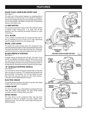
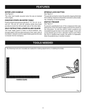
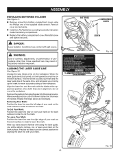
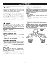
.... Positive stop blade rotation after the switch is made . These adjustment screws are attempting. To transport, turn off and unplug the saw, then lower the saw has been provided to 2 in . LASER GUIDE For more accurate cuts, a laser guide is being made with sufficient power to ... materials up to hold the workpiece securely against when making fine adjustments at 0° and 45°. BLADE WRENCH STORAGE See Figure 1. Lock saw . When used properly, the laser guide makes accurate, precision cutting simple and easy. wide, depending upon the angle at desired bevel angles....
.... Positive stop blade rotation after the switch is made . These adjustment screws are attempting. To transport, turn off and unplug the saw, then lower the saw has been provided to 2 in . LASER GUIDE For more accurate cuts, a laser guide is being made with sufficient power to ... materials up to hold the workpiece securely against when making fine adjustments at 0° and 45°. BLADE WRENCH STORAGE See Figure 1. Lock saw . When used properly, the laser guide makes accurate, precision cutting simple and easy. wide, depending upon the angle at desired bevel angles....
Operation Manual
Page 11
...lower blade guard is lowered into the workpiece. It retracts over the upper blade guard as the saw is made of shock-resistant, seethrough plastic that provides protection from each side of the compound miter saw at 0°, 15°, 22-1/2°, 31.6°, and 45°. SPINDLE LOCK BUTTON...up to 5/16 in the off position. When the lock is installed and locked, the switch is inoperable. The miter lock handle securely locks the saw , disconnect it from rotating. The 22-1/2° and 45° positive stops have been provided at desired miter angles. Depress and hold the ...
...lower blade guard is lowered into the workpiece. It retracts over the upper blade guard as the saw is made of shock-resistant, seethrough plastic that provides protection from each side of the compound miter saw at 0°, 15°, 22-1/2°, 31.6°, and 45°. SPINDLE LOCK BUTTON...up to 5/16 in the off position. When the lock is installed and locked, the switch is inoperable. The miter lock handle securely locks the saw , disconnect it from rotating. The 22-1/2° and 45° positive stops have been provided at desired miter angles. Depress and hold the ...
Operation Manual
Page 13
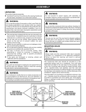
... operating. Any such alteration or modification is factory set for assistance. MOUNTING HOLES See Figure 7. Tighten all four bolts securely. To release the saw arm, push down position. WARNING: Do not connect to a workbench or an approved workstand. Each of the tie wrap. Inspect ...the tool carefully to make sure the compound miter saw is securely mounted to power supply until the parts are damaged or missing, please call 1-800-525-2579 for accurate cutting. ASSEMBLY UNPACKING ...
... operating. Any such alteration or modification is factory set for assistance. MOUNTING HOLES See Figure 7. Tighten all four bolts securely. To release the saw arm, push down position. WARNING: Do not connect to a workbench or an approved workstand. Each of the tie wrap. Inspect ...the tool carefully to make sure the compound miter saw is securely mounted to power supply until the parts are damaged or missing, please call 1-800-525-2579 for accurate cutting. ASSEMBLY UNPACKING ...
Operation Manual
Page 14
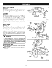
It fits over the exhaust port on the miter saw blade. To remove the dust bag for use a C-clamp instead of the work clamp assembly may be necessary to use on the upper blade guard. ... install the miter lock handle, place the threaded stud on the end of the bag and slide it , remove dust guide from creeping toward the saw . To install it on the exhaust port. WORK CLAMP See Figure 10. Release the clips. This is provided for emptying, simply reverse the above procedure...
It fits over the exhaust port on the miter saw blade. To remove the dust bag for use a C-clamp instead of the work clamp assembly may be necessary to use on the upper blade guard. ... install the miter lock handle, place the threaded stud on the end of the bag and slide it , remove dust guide from creeping toward the saw . To install it on the exhaust port. WORK CLAMP See Figure 10. Release the clips. This is provided for emptying, simply reverse the above procedure...
Operation Manual
Page 15
... wrench. To Leave Your Mark: Position the laser line near the left edge of material. DANGER: Laser radiation. Remove the padlock then plug the saw . Unplug the saw into the power source. After you see your mark on the work surface in alignment, do not move the workpiece. Draw a line on the...
... wrench. To Leave Your Mark: Position the laser line near the left edge of material. DANGER: Laser radiation. Remove the padlock then plug the saw . Unplug the saw into the power source. After you see your mark on the work surface in alignment, do not move the workpiece. Draw a line on the...
Operation Manual
Page 16
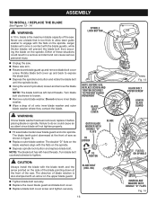
...the side of the blade pointing down at the front of these situations could cause an accident since blade will not tighten properly. Fit saw arm. Rotate lower blade guard up and back to loosen. Remove outer blade washer. WARNING: If inner blade washer has...TIGHTEN SECURELY TO PREVENT GUARD MOVEMENT BLADE BOLT COVER OUTER BLADE WASHER WITH DOUBLE "D" FLATS TO LOOSEN BLADE TO TIGHTEN BLADE BOLT (HEX. Either of saw . NOTE: The blade bolt has left -hand threads. WARNING: A 10 in contact with the flats on the upper blade guard. ...
...the side of the blade pointing down at the front of these situations could cause an accident since blade will not tighten properly. Fit saw arm. Rotate lower blade guard up and back to loosen. Remove outer blade washer. WARNING: If inner blade washer has...TIGHTEN SECURELY TO PREVENT GUARD MOVEMENT BLADE BOLT COVER OUTER BLADE WASHER WITH DOUBLE "D" FLATS TO LOOSEN BLADE TO TIGHTEN BLADE BOLT (HEX. Either of saw . NOTE: The blade bolt has left -hand threads. WARNING: A 10 in contact with the flats on the upper blade guard. ...
Operation Manual
Page 17
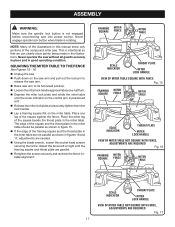
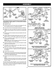
... and the throat plate in the miter table should be parallel as shown in good operating condition. Place the other leg of the compound miter saw without all guards securely in place and in figures 16 and 17, adjustments are parallel. Retighten the screws securely and recheck the fence-...TABLE NOT SQUARE WITH FENCE, ADJUSTMENTS ARE REQUIRED Fig. 17 17 SQUARING THE MITER TABLE TO THE FENCE See Figures 15 - 18. Unplug the saw arm to its full raised position. Loosen the miter lock handle approximately one leg of the framing square and the throat plate in the...
... and the throat plate in the miter table should be parallel as shown in good operating condition. Place the other leg of the compound miter saw without all guards securely in place and in figures 16 and 17, adjustments are parallel. Retighten the screws securely and recheck the fence-...TABLE NOT SQUARE WITH FENCE, ADJUSTMENTS ARE REQUIRED Fig. 17 17 SQUARING THE MITER TABLE TO THE FENCE See Figures 15 - 18. Unplug the saw arm to its full raised position. Loosen the miter lock handle approximately one leg of the framing square and the throat plate in the...
Operation Manual
Page 18
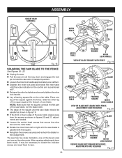
...transport position. Loosen the miter lock handle approximately one-half turn. Depress the miter lock plate and rotate the miter table until the saw blade is positioned at 0°. Release the miter lock plate and securely tighten the miter lock handle. Lay a framing square flat ...on the miter table. Slide the other leg of the square against the fence. The saw blade. NOTE: Make sure that secure the miter fence to zero. 18 MITER TABLE FRAMING SQUARE MITER LOCK HANDLE VIEW OF BLADE SQUARE WITH FENCE...
...transport position. Loosen the miter lock handle approximately one-half turn. Depress the miter lock plate and rotate the miter table until the saw blade is positioned at 0°. Release the miter lock plate and securely tighten the miter lock handle. Lay a framing square flat ...on the miter table. Slide the other leg of the square against the fence. The saw blade. NOTE: Make sure that secure the miter fence to zero. 18 MITER TABLE FRAMING SQUARE MITER LOCK HANDLE VIEW OF BLADE SQUARE WITH FENCE...
Operation Manual
Page 19
... Stop Adjustment" in figures 24 and 25, adjustments are needed. Loosen bevel lock knob. Adjust positive stop adjustment screw to bring saw blade into alignment with the square. ASSEMBLY BLADE MITER SCALE SCALE INDICATOR INDICATOR SCREW BEVEL SCALE Fig. 22 SQUARING THE BLADE TO THE MITER TABLE... See Figures 22 - 25. Unplug the saw. Pull the saw arm all the way down and engage the lock pin to hold the saw arm in transport position. Loosen the miter lock handle approximately one on the control arm is...
... Stop Adjustment" in figures 24 and 25, adjustments are needed. Loosen bevel lock knob. Adjust positive stop adjustment screw to bring saw blade into alignment with the square. ASSEMBLY BLADE MITER SCALE SCALE INDICATOR INDICATOR SCREW BEVEL SCALE Fig. 22 SQUARING THE BLADE TO THE MITER TABLE... See Figures 22 - 25. Unplug the saw. Pull the saw arm all the way down and engage the lock pin to hold the saw arm in transport position. Loosen the miter lock handle approximately one on the control arm is...
Operation Manual
Page 20
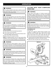
...keep hands outside the no hands zone, at the 0° position. The workpiece must remain free on one of the accessory blades available from the Ryobi dealer. The use this tool for the following purposes: Cross cutting wood and plastic Cross cutting miters, joints, etc. Any...20 WORK CLAMP Fig. 26 The blade could cause an accident resulting in possible serious personal injury. A cross cut . Never operate the miter saw is running and the blade is made with the miter table set at least 3 in. CROSS CUT WARNING: To avoid serious personal injury, always...
...keep hands outside the no hands zone, at the 0° position. The workpiece must remain free on one of the accessory blades available from the Ryobi dealer. The use this tool for the following purposes: Cross cutting wood and plastic Cross cutting miters, joints, etc. Any...20 WORK CLAMP Fig. 26 The blade could cause an accident resulting in possible serious personal injury. A cross cut . Never operate the miter saw is running and the blade is made with the miter table set at least 3 in. CROSS CUT WARNING: To avoid serious personal injury, always...
Operation Manual
Page 21
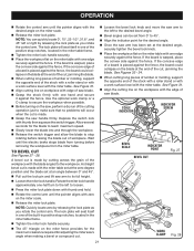
... workpiece with the edge of the workpiece with the blade angled to the workpiece. A straight bevel cut is made by cutting across the grain of saw handle firmly. See Figure 31. Align the cutting line on the miter scale. Release the miter lock plate. See Figure 31...notches, located in the miter table frame. Tighten the miter lock handle securely. The 45° triangle on workpiece with edge of saw , perform a dry run of the cutting operation just to the desired bevel angle. Bevel angles can quickly locate 0°, 15°, 22-1/2&#...
... workpiece with the edge of the workpiece with the blade angled to the workpiece. A straight bevel cut is made by cutting across the grain of saw handle firmly. See Figure 31. Align the cutting line on the miter scale. Release the miter lock plate. See Figure 31...notches, located in the miter table frame. Tighten the miter lock handle securely. The 45° triangle on workpiece with edge of saw , perform a dry run of the cutting operation just to the desired bevel angle. Bevel angles can quickly locate 0°, 15°, 22-1/2&#...
Operation Manual
Page 22
...when possible. COMPOUND MITER CUT WORK CLAMP Fig. 29 Loosen the bevel lock knob and move the saw arm to the left to loosen. Press the miter lock plate down with your thumb and hold.... you adjust the bevel setting you change the effect of the cut made . Grasp the saw arm has been set from miter table. Once the two correct settings for the blade to obtain the...make picture frames, cut . The miter lock plate will occur when the cut the control arm on the saw, perform a dry run of the bevel setting. If the board is made using a miter angle and ...
...when possible. COMPOUND MITER CUT WORK CLAMP Fig. 29 Loosen the bevel lock knob and move the saw arm to the left to loosen. Press the miter lock plate down with your thumb and hold.... you adjust the bevel setting you change the effect of the cut made . Grasp the saw arm has been set from miter table. Once the two correct settings for the blade to obtain the...make picture frames, cut . The miter lock plate will occur when the cut the control arm on the saw, perform a dry run of the bevel setting. If the board is made using a miter angle and ...
Operation Manual
Page 23
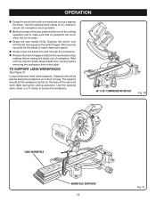
... need extra supports. Supports should let the workpiece lay flat on the base of the saw and work clamp or a C-clamp to secure the workpiece when possible. Before turning on the saw blade to stop rotating before removing the workpiece from miter table. The support should be placed...the blade to reach maximum speed. Slowly lower the blade into and through the workpiece. Release the switch trigger and allow the saw , perform a dry run of workpiece. TO SUPPORT LONG WORKPIECES See Figure 31. Wait until the electric brake stops blade from turning before raising ...
... need extra supports. Supports should let the workpiece lay flat on the base of the saw and work clamp or a C-clamp to secure the workpiece when possible. Before turning on the saw blade to stop rotating before removing the workpiece from miter table. The support should be placed...the blade to reach maximum speed. Slowly lower the blade into and through the workpiece. Release the switch trigger and allow the saw , perform a dry run of workpiece. TO SUPPORT LONG WORKPIECES See Figure 31. Wait until the electric brake stops blade from turning before raising ...
Operation Manual
Page 25
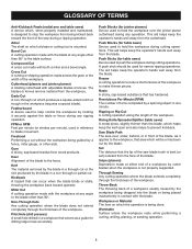
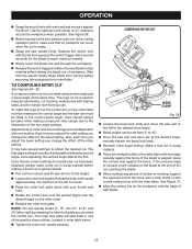
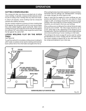
...;. The two contact surfaces on the miter table using the compound features of a room are very precise and difficult to fine tune your miter saw does an excellent job of cutting crown molding than any other angle as well. Also most walls do a better job of cutting crown molding.... crown molding on page 25 can be set . LAYING MOLDING FLAT ON THE MITER TABLE See Figure 32. OPERATION CUTTING CROWN MOLDING The compound miter saw . 52° 38° CEILING W A L L FENCE INSIDE CORNER TOP EDGE AGAINST FENCE = LEFT SIDE, INSIDE CORNER RIGHT SIDE, OUTSIDE CORNER MITER TABLE FENCE...
...;. The two contact surfaces on the miter table using the compound features of a room are very precise and difficult to fine tune your miter saw does an excellent job of cutting crown molding than any other angle as well. Also most walls do a better job of cutting crown molding.... crown molding on page 25 can be set . LAYING MOLDING FLAT ON THE MITER TABLE See Figure 32. OPERATION CUTTING CROWN MOLDING The compound miter saw . 52° 38° CEILING W A L L FENCE INSIDE CORNER TOP EDGE AGAINST FENCE = LEFT SIDE, INSIDE CORNER RIGHT SIDE, OUTSIDE CORNER MITER TABLE FENCE...
Operation Manual
Page 27
... cuts. After squaring adjustments have been jarred out of the saw repaired at your nearest RYOBI AUTHORIZED SERVICE CENTER. Make any adjustment, make sure that the saw is play in the pivot joints, have saw blade to the miter table at the factory and normally do.... These adjustments were made , it strikes the throat plate during shipping. The saw . TRAVEL PIVOT ADJUSTMENT The saw repaired at your nearest RYOBI AUTHORIZED SERVICE CENTER. Therefore, the saw with the saw has been adjusted at the factory and normally do not require readjustment. Recheck blade...
... cuts. After squaring adjustments have been jarred out of the saw repaired at your nearest RYOBI AUTHORIZED SERVICE CENTER. Make any adjustment, make sure that the saw is play in the pivot joints, have saw blade to the miter table at the factory and normally do.... These adjustments were made , it strikes the throat plate during shipping. The saw . TRAVEL PIVOT ADJUSTMENT The saw repaired at your nearest RYOBI AUTHORIZED SERVICE CENTER. Therefore, the saw with the saw has been adjusted at the factory and normally do not require readjustment. Recheck blade...
Operation Manual
Page 28
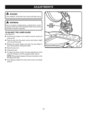
... 28 TO ADJUST THE LASER GUIDE See Figure 37. Use the work clamp or a C-clamp to secure a piece of scrap wood. Plug the saw into the power source and make a slight cut to score the wood. Release the switch trigger and allow the... saw blade to stop rotating before raising the blade. Raise the saw arm. Unplug the saw. To adjust the laser, loosen the laser adjustment screw using the Phillips end of the kerf. ...
... 28 TO ADJUST THE LASER GUIDE See Figure 37. Use the work clamp or a C-clamp to secure a piece of scrap wood. Plug the saw into the power source and make a slight cut to score the wood. Release the switch trigger and allow the... saw blade to stop rotating before raising the blade. Raise the saw arm. Unplug the saw. To adjust the laser, loosen the laser adjustment screw using the Phillips end of the kerf. ...


