
Operation Manual
Page 2
... hands away from an outlet. The plug will require the use of a polarized extension cord. A polarized extension cord will void your body away from heat, oil, sharp edges, or moving parts. Wear heavy long pants, long sleeves, boots, and gloves. It will fit into a polarized extension cord only one way. This...
... hands away from an outlet. The plug will require the use of a polarized extension cord. A polarized extension cord will void your body away from heat, oil, sharp edges, or moving parts. Wear heavy long pants, long sleeves, boots, and gloves. It will fit into a polarized extension cord only one way. This...
Operation Manual
Page 4
... may affect its intended function. Keep handles dry, clean, and free from power source when not in use this manual. Disconnect the plug from oil and grease. Check damaged parts. Inspect extension cords periodically and replace if damaged. A guard or other part that may use , before servicing, and when...
... may affect its intended function. Keep handles dry, clean, and free from power source when not in use this manual. Disconnect the plug from oil and grease. Check damaged parts. Inspect extension cords periodically and replace if damaged. A guard or other part that may use , before servicing, and when...

Operation Manual
Page 8
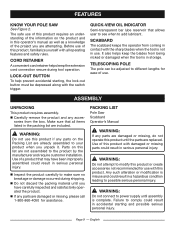
English SCABBARD Fig. 2 Cutting Capacity...6 in . Chain Pitch...3/8 in . Chain Type Low Profile Skip Tooth Narrow Kerf Input Nominal 120V/60Hz AC only, 6 Amps OIL CAP TELESCOPING POLE LOCK-OUT BUTTON CORD RETAINER Page 8 - FEATURES PRODUCT SPECIFICATIONS Bar Length...8 in.
English SCABBARD Fig. 2 Cutting Capacity...6 in . Chain Pitch...3/8 in . Chain Type Low Profile Skip Tooth Narrow Kerf Input Nominal 120V/60Hz AC only, 6 Amps OIL CAP TELESCOPING POLE LOCK-OUT BUTTON CORD RETAINER Page 8 - FEATURES PRODUCT SPECIFICATIONS Bar Length...8 in.
Operation Manual
Page 9
... could result in accidental starting , the lock-out button must be adjusted to make sure no breakage or damage occurred during tool operation. QUICK-VIEW OIL INDICATOR Semi-transparent bar lube reservoir that may have carefully inspected and satisfactorily operated the product. WARNING: Do not connect to the product by the...
... could result in accidental starting , the lock-out button must be adjusted to make sure no breakage or damage occurred during tool operation. QUICK-VIEW OIL INDICATOR Semi-transparent bar lube reservoir that may have carefully inspected and satisfactorily operated the product. WARNING: Do not connect to the product by the...
Operation Manual
Page 11
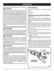
... period of time (three months or longer) be checked after each use this product to perform over a wide temperature range with no bar and chain oil added. English Fig. 4 Continue to inflict serious injury. NOTE: It is below : n Limbing n Pruning ADDING BAR AND CHAIN LUBRICANT See Figure ...4 Use Bar and Chain Lubricant. WARNING: Do not allow familiarity with no dilution required. n Check and fill the oil tank when quick view oil indicator is normal for one minute. Disconnect the electrical service to the damaged line or cord before attempting to free the bar ...
... period of time (three months or longer) be checked after each use this product to perform over a wide temperature range with no bar and chain oil added. English Fig. 4 Continue to inflict serious injury. NOTE: It is below : n Limbing n Pruning ADDING BAR AND CHAIN LUBRICANT See Figure ...4 Use Bar and Chain Lubricant. WARNING: Do not allow familiarity with no dilution required. n Check and fill the oil tank when quick view oil indicator is normal for one minute. Disconnect the electrical service to the damaged line or cord before attempting to free the bar ...
Operation Manual
Page 15
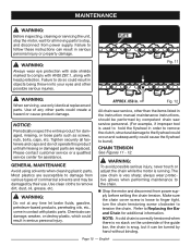
... parts. Use clean cloths to the flywheel could occur and subsequently could result in order to remove the clutch, structural damage to remove dirt, dust, oil, grease, etc. APPROX .050 in contact with head protection. The saw service personnel. (For example, if improper tool is no slack on the underside of...
... parts. Use clean cloths to the flywheel could occur and subsequently could result in order to remove the clutch, structural damage to remove dirt, dust, oil, grease, etc. APPROX .050 in contact with head protection. The saw service personnel. (For example, if improper tool is no slack on the underside of...
Operation Manual
Page 17
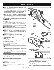
... wood and the size of the bar up and tighten the chain cover screw securely. For smooth and fast cutting, the chain needs to the oil pump, bar, or chain. Fig. 18 n Improper filing angle of the side plate can be maintained properly.
... wood and the size of the bar up and tighten the chain cover screw securely. For smooth and fast cutting, the chain needs to the oil pump, bar, or chain. Fig. 18 n Improper filing angle of the side plate can be maintained properly.

Parts Diagram
Page 3
PART NO. PART NO. DESCRIPTION QTY. 1 994019001 Hex Bolt 1 9 994013001 Oil Outlet Seal Ring 1 2 994068001 Chain Cover Assembly (Inc. Key 5) 1 10 994006001 Retaining Ring 1 3 994017001 External Washer 1 11 994005001 Sprocket 1 4 994016001 Retaining Ring 1 12 994004001 Tension Spring 1 5 994014001 Chain Cover Seal Ring 1 13 994066001 Oil Cap 1 6 901289001 Chain 1 Not Shown: 7 994065001 Bar 8 994067001 Chain Adjustment Assembly 1 994012001 Scabbard 1 990000717 Operator's Manual 3 KEY NO. FIGURE A KEY NO. DESCRIPTION QTY. RY43161 PARTS LIST -
PART NO. PART NO. DESCRIPTION QTY. 1 994019001 Hex Bolt 1 9 994013001 Oil Outlet Seal Ring 1 2 994068001 Chain Cover Assembly (Inc. Key 5) 1 10 994006001 Retaining Ring 1 3 994017001 External Washer 1 11 994005001 Sprocket 1 4 994016001 Retaining Ring 1 12 994004001 Tension Spring 1 5 994014001 Chain Cover Seal Ring 1 13 994066001 Oil Cap 1 6 901289001 Chain 1 Not Shown: 7 994065001 Bar 8 994067001 Chain Adjustment Assembly 1 994012001 Scabbard 1 990000717 Operator's Manual 3 KEY NO. FIGURE A KEY NO. DESCRIPTION QTY. RY43161 PARTS LIST -

Parts Diagram
Page 5
... Lock Spring 2 22 993996001 Rubber Plug 4 8 994178001 Upper Pole Shaft Assembl (Inc. Key No. 7) 1 23 994061001 Oil Pump Assembly 1 9 994176001 Pole Coupler 2 24 993990001 Oil Tank Assembly 1 10 994177001 Lower Pole Shaft Assembly (Inc. DESCRIPTION QTY. PART NO. DESCRIPTION QTY. 1 994045001 Screw (M4...x 35 mm) 2 WARNING: Improper repair of your tool requires safety testing and should only be performed by a RYOBI Authorized Service Center. RY43161 PARTS LIST - KEY NO. Any repairs requiring disassembly of a double insulated tool can result in damages to the ...
... Lock Spring 2 22 993996001 Rubber Plug 4 8 994178001 Upper Pole Shaft Assembl (Inc. Key No. 7) 1 23 994061001 Oil Pump Assembly 1 9 994176001 Pole Coupler 2 24 993990001 Oil Tank Assembly 1 10 994177001 Lower Pole Shaft Assembly (Inc. DESCRIPTION QTY. PART NO. DESCRIPTION QTY. 1 994045001 Screw (M4...x 35 mm) 2 WARNING: Improper repair of your tool requires safety testing and should only be performed by a RYOBI Authorized Service Center. RY43161 PARTS LIST - KEY NO. Any repairs requiring disassembly of a double insulated tool can result in damages to the ...


