
Operation Manual
Page 3
...; READ ALL INSTRUCTIONS For safe operation, read and understand all safety instructions. Do not use the product for any damaged parts before using this product which it is on handles when power is intended. Do not operate from cutting area. Blade coasts after being turned off. Do not grasp the exposed cutting blades or cutting edges when picking up place - Replace any job...
...; READ ALL INSTRUCTIONS For safe operation, read and understand all safety instructions. Do not use the product for any damaged parts before using this product which it is on handles when power is intended. Do not operate from cutting area. Blade coasts after being turned off. Do not grasp the exposed cutting blades or cutting edges when picking up place - Replace any job...
Operation Manual
Page 4
...; Use only the replacement guide bars and low kickback chains specified for you are operating the unit. This unit should be carefully checked to accidents. Use pole saw chain and be whipped toward you or pull you off balance. When cutting a limb that is pinched along the top of overhead electrical lines. Before starting - Keep cutting edge sharp and clean for alignment of moving parts...
...; Use only the replacement guide bars and low kickback chains specified for you are operating the unit. This unit should be carefully checked to accidents. Use pole saw chain and be whipped toward you or pull you off balance. When cutting a limb that is pinched along the top of overhead electrical lines. Before starting - Keep cutting edge sharp and clean for alignment of moving parts...
Operation Manual
Page 5
... dry, and high or locked-up or holding the appliance. SAVE THESE INSTRUCTIONS Page 5 - SSPPEECCIIFFIICCSSAAFFEETTYYRRUULLEESS Keep handles dry, clean, and free from oil and grease. Service on the product must be recharged only with 40 V power head, use 40 V lithium-ion battery packs. n Remove the battery pack from the pole saw before servicing, cleaning or removing material from the unit, changing accessories such as the bar and chain, or when...
... dry, and high or locked-up or holding the appliance. SAVE THESE INSTRUCTIONS Page 5 - SSPPEECCIIFFIICCSSAAFFEETTYYRRUULLEESS Keep handles dry, clean, and free from oil and grease. Service on the product must be recharged only with 40 V power head, use 40 V lithium-ion battery packs. n Remove the battery pack from the pole saw before servicing, cleaning or removing material from the unit, changing accessories such as the bar and chain, or when...
Operation Manual
Page 6
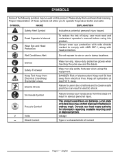
... with head protection. Keep tool 50 feet away from Electrical Lines/Keep Bystanders Away Electric Shock No Hands Symbol Recycle Symbol V Volts Direct Current Wear non-slip, heavy-duty protective gloves when handling the pole saw and the blade. Wet Conditions Alert Do not expose to rain or use in dry conditions and to use in damp locations. Wear...
... with head protection. Keep tool 50 feet away from Electrical Lines/Keep Bystanders Away Electric Shock No Hands Symbol Recycle Symbol V Volts Direct Current Wear non-slip, heavy-duty protective gloves when handling the pole saw and the blade. Wet Conditions Alert Do not expose to rain or use in dry conditions and to use in damp locations. Wear...

Operation Manual
Page 8
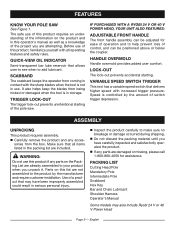
... Bar Length 8 in . English Fig. 1 Ryobi 24V and 40V Power Head If purchased with 24 V power head: Motor 24 Volts DC If purchased with 40 V power head: Motor 40 Volts DC TRIGGER LOCK OUT POLE SAW ATTACHMENT WITH 24 V POWER HEAD ADJUSTABLE FRONT HANDLE SWITCH TRIGGER POLE SAW ATTACHMENT WITH 40 V POWER HEAD TRIGGER LOCK OUT INTERMEDIATE POLE ADJUSTABLE FRONT HANDLE SWITCH TRIGGER POLE SAW ATTACHMENT MANDATORY POLE CUTTING HEAD POLE OIL CAP POLE SAW ATTACHMENT INTERMEDIATE POLE MANDATORY POLE CUTTING HEAD POLE OIL CAP Page 8 - Chain Pitch 3/8 in. Chain Type...
... Bar Length 8 in . English Fig. 1 Ryobi 24V and 40V Power Head If purchased with 24 V power head: Motor 24 Volts DC If purchased with 40 V power head: Motor 40 Volts DC TRIGGER LOCK OUT POLE SAW ATTACHMENT WITH 24 V POWER HEAD ADJUSTABLE FRONT HANDLE SWITCH TRIGGER POLE SAW ATTACHMENT WITH 40 V POWER HEAD TRIGGER LOCK OUT INTERMEDIATE POLE ADJUSTABLE FRONT HANDLE SWITCH TRIGGER POLE SAW ATTACHMENT MANDATORY POLE CUTTING HEAD POLE OIL CAP POLE SAW ATTACHMENT INTERMEDIATE POLE MANDATORY POLE CUTTING HEAD POLE OIL CAP Page 8 - Chain Pitch 3/8 in. Chain Type...
Operation Manual
Page 9
... the tool is in this product, familiarize yourself with increased trigger pressure. Use of control, and can be positioned above or below the coupler. PACKING LIST Cutting Head Pole Mandatory Pole Intermediate Pole Scabbard Hex Key Bar and Chain Lubricant Shoulder Harness Operator's Manual Some models may have carefully inspected and satisfactorily operated the product. TRIGGER LOCK-OUT The trigger lock-out prevents unintentional starting . n Carefully remove the product and any parts...
... the tool is in this product, familiarize yourself with increased trigger pressure. Use of control, and can be positioned above or below the coupler. PACKING LIST Cutting Head Pole Mandatory Pole Intermediate Pole Scabbard Hex Key Bar and Chain Lubricant Shoulder Harness Operator's Manual Some models may have carefully inspected and satisfactorily operated the product. TRIGGER LOCK-OUT The trigger lock-out prevents unintentional starting . n Carefully remove the product and any parts...

Operation Manual
Page 10
... pole. English ASSEMBLY WARNING: If any attachment while power head is running or with the battery pack installed. CONNECTING THE POLE SAW ATTACHMENT See Figure 2. n Lower the collar on the power head to the mandatory pole. WARNING: Failure to possible serious personal injury. Use of a coupler device that could result in serious injury or death. WARNING: Never install, remove, or adjust any parts are replaced. n Repeat this...
... pole. English ASSEMBLY WARNING: If any attachment while power head is running or with the battery pack installed. CONNECTING THE POLE SAW ATTACHMENT See Figure 2. n Lower the collar on the power head to the mandatory pole. WARNING: Failure to possible serious personal injury. Use of a coupler device that could result in serious injury or death. WARNING: Never install, remove, or adjust any parts are replaced. n Repeat this...

Operation Manual
Page 11
40 VOLT POWER HEAD ASSEMBLY 24 VOLT POWER HEAD POWER HEAD COLLAR SOCKET PLUG INTERMEDIATE POLE THREADED BASE MANDATORY POLE COLLAR THREADED BASE SOCKET COLLAR CUTTING HEAD POLE POLE SAW ATTACHMENT ATTACHING THE SHOULDER HARNESS See Figure 3. n Connect the latches on power head. English PLUG Fig. 2 LATCH Fig. 3 STRAP HANGER Page 11 - n Adjust the strap to the strap hanger on the shoulder harness to a comfortable position.
40 VOLT POWER HEAD ASSEMBLY 24 VOLT POWER HEAD POWER HEAD COLLAR SOCKET PLUG INTERMEDIATE POLE THREADED BASE MANDATORY POLE COLLAR THREADED BASE SOCKET COLLAR CUTTING HEAD POLE POLE SAW ATTACHMENT ATTACHING THE SHOULDER HARNESS See Figure 3. n Connect the latches on power head. English PLUG Fig. 2 LATCH Fig. 3 STRAP HANGER Page 11 - n Adjust the strap to the strap hanger on the shoulder harness to a comfortable position.
Operation Manual
Page 12
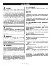
... electric sources. Page 12 - OPERATION DANGER: Never cut near power lines, electric cords, or other conductive parts of use of a second is sufficient to inflict serious injury. If bar and chain jams on the chain and bar sprocket. The use and refilled as needed . Remove the battery pack, if installed. Level should also be sure the chain is lightly lubricated; n Wipe off excess oil. Damage may use then run for the purposes listed...
... electric sources. Page 12 - OPERATION DANGER: Never cut near power lines, electric cords, or other conductive parts of use of a second is sufficient to inflict serious injury. If bar and chain jams on the chain and bar sprocket. The use and refilled as needed . Remove the battery pack, if installed. Level should also be sure the chain is lightly lubricated; n Wipe off excess oil. Damage may use then run for the purposes listed...

Operation Manual
Page 13
... the battery pack. Remove the battery pack. SWITCH TRIGGER LOCK-OUT BUTTON 24 V BATTERY STARTING AND STOPPING See Figures 5 and 7. Removing battery pack will automatically reset to fall out, resulting in the power head battery port before beginning operation. SWITCH TRIGGER LATCH Page 13 - WARNING: Always remove battery pack from your tool when you are assembling parts, making adjustments, cleaning, or when not in use. To start the motor: n Hold the pole saw . OPERATION TO INSTALL BATTERY PACK See...
... the battery pack. Remove the battery pack. SWITCH TRIGGER LOCK-OUT BUTTON 24 V BATTERY STARTING AND STOPPING See Figures 5 and 7. Removing battery pack will automatically reset to fall out, resulting in the power head battery port before beginning operation. SWITCH TRIGGER LATCH Page 13 - WARNING: Always remove battery pack from your tool when you are assembling parts, making adjustments, cleaning, or when not in use. To start the motor: n Hold the pole saw . OPERATION TO INSTALL BATTERY PACK See...
Operation Manual
Page 14
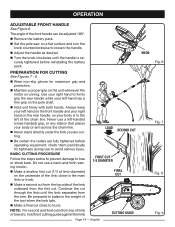
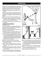
... or trunk. The angle of the limb outboard from the first cut through the limb until the handle is running. PREPARATION FOR CUTTING See Figures 7 - 9. n Make a second cut from the top side of the front handle can be adjusted 180°. Remove the battery pack. Set the pole saw on the unit whenever the motor is securely tightened before operating equipment;
... or trunk. The angle of the limb outboard from the first cut through the limb until the handle is running. PREPARATION FOR CUTTING See Figures 7 - 9. n Make a second cut from the top side of the front handle can be adjusted 180°. Remove the battery pack. Set the pole saw on the unit whenever the motor is securely tightened before operating equipment;
Operation Manual
Page 15
... to the bar, chain, or motor can be reached from the ground, lift the limb while holding the saw with a firm grip. Page 15 - n Branches may fall . n Work slowly, keeping both hands on the specific situation, as the cut , damage to fall in diameter. English n Plan the cut . If you and the chain while limbing. n Release the trigger as...
... to the bar, chain, or motor can be reached from the ground, lift the limb while holding the saw with a firm grip. Page 15 - n Branches may fall . n Work slowly, keeping both hands on the specific situation, as the cut , damage to fall in diameter. English n Plan the cut . If you and the chain while limbing. n Release the trigger as...
Operation Manual
Page 16
... tensioned warm chain will increase. Make sure the chain cover screw is running. n Chain must be damaged by hand without binding. Failure to comply with ANSI Z87.1, along with plastic parts. FLATS WARNING: Always wear eye protection with side shields marked to follow these maintenance instructions, should be turned by their use only identical replacement parts. The drive links of the guide bar, the chain is snug...
... tensioned warm chain will increase. Make sure the chain cover screw is running. n Chain must be damaged by hand without binding. Failure to comply with ANSI Z87.1, along with plastic parts. FLATS WARNING: Always wear eye protection with side shields marked to follow these maintenance instructions, should be turned by their use only identical replacement parts. The drive links of the guide bar, the chain is snug...
Operation Manual
Page 17
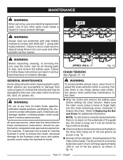
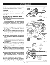
.... Check the "cold tension" before replacing the bar, chain, or performing any maintenance operation. CHAIN COVER CHAIN COVER SCREW BAR CHAIN Fig. 14 WARNING: To avoid possible serious injury, stop the motor and remove the battery pack before next use. n Replace the chain cover and reinstall the washer and screw. Tighten the screw finger tight only. REPLACING THE BAR AND CHAIN See Figures 14 - 17. n The bar contains a slot that the chain tensioning pin fits into the chain tensioning pin...
.... Check the "cold tension" before replacing the bar, chain, or performing any maintenance operation. CHAIN COVER CHAIN COVER SCREW BAR CHAIN Fig. 14 WARNING: To avoid possible serious injury, stop the motor and remove the battery pack before next use. n Replace the chain cover and reinstall the washer and screw. Tighten the screw finger tight only. REPLACING THE BAR AND CHAIN See Figures 14 - 17. n The bar contains a slot that the chain tensioning pin fits into the chain tensioning pin...
Operation Manual
Page 18
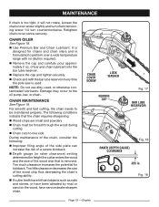
... rotate. n Remove the cap and carefully pour approximately 2 oz. Loosen the chain cover screw slightly and turn chain tensioning screw 1/4 turn counterclockwise. n Check and refill the bar lube reservoir every time the pole saw is removed. n Use Premium Bar and Chain Lubricant. CHAIN MAINTENANCE See Figure 19. n Depth gauge (or raker clearance) setting determines the height the cutter enters the wood and the size of a severe kickback. CHAIN COVER SCREW LOCK WASHER REMOVE CAP Fig. 17 BAR LUBE RESERVOIR...
... rotate. n Remove the cap and carefully pour approximately 2 oz. Loosen the chain cover screw slightly and turn chain tensioning screw 1/4 turn counterclockwise. n Check and refill the bar lube reservoir every time the pole saw is removed. n Use Premium Bar and Chain Lubricant. CHAIN MAINTENANCE See Figure 19. n Depth gauge (or raker clearance) setting determines the height the cutter enters the wood and the size of a severe kickback. CHAIN COVER SCREW LOCK WASHER REMOVE CAP Fig. 17 BAR LUBE RESERVOIR...
Operation Manual
Page 19
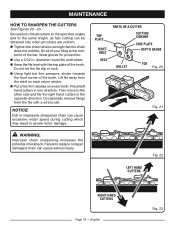
... cause serious injury. Occasionally remove filings from the steel on every tooth. Failure to replace or repair damaged chain can cause excessive motor speed during cutting which may result in the opposite direction. Do not let the file dip or rock. File all of your filing at the midpoint of the tooth. n Keep the file level with a wire brush. MAINTENANCE HOW TO SHARPEN THE CUTTERS See...
... cause serious injury. Occasionally remove filings from the steel on every tooth. Failure to replace or repair damaged chain can cause excessive motor speed during cutting which may result in the opposite direction. Do not let the file dip or rock. File all of your filing at the midpoint of the tooth. n Keep the file level with a wire brush. MAINTENANCE HOW TO SHARPEN THE CUTTERS See...
Operation Manual
Page 20
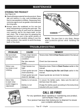
... protective gloves when handling the chain. Check guide bar and chain assembly. To secure the battery pack, make sure the latch (or latches) snap into place. MAINTENANCE STORING THE PRODUCT See Figure 24. Clean all foreign material from corrosive agents such as shown. Refer to ensure your product, call the Ryobi® Help Line! Use caution to Replacing the Bar and Chain earlier in this...
... protective gloves when handling the chain. Check guide bar and chain assembly. To secure the battery pack, make sure the latch (or latches) snap into place. MAINTENANCE STORING THE PRODUCT See Figure 24. Clean all foreign material from corrosive agents such as shown. Refer to ensure your product, call the Ryobi® Help Line! Use caution to Replacing the Bar and Chain earlier in this...
Operation Manual
Page 21
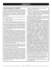
... (Authorized Ryobi Service Center). Tune-ups - Wear items - Bump Knobs, Outer Spools, Cutting Lines, Inner Reels, Starter Pulleys, Starter Ropes, Drive Belts, Tines, Felt Washers, Hitch Pins, Mulching Blades, Blower Fans, Blower and Vacuum Tubes, Vacuum Bag and Straps, Guide Bars, Saw Chains Techtronic Industries North America, Inc., reserves the right to change or improve the design of any product that is used for personal, family or household use of improper maintenance or to...
... (Authorized Ryobi Service Center). Tune-ups - Wear items - Bump Knobs, Outer Spools, Cutting Lines, Inner Reels, Starter Pulleys, Starter Ropes, Drive Belts, Tines, Felt Washers, Hitch Pins, Mulching Blades, Blower Fans, Blower and Vacuum Tubes, Vacuum Bag and Straps, Guide Bars, Saw Chains Techtronic Industries North America, Inc., reserves the right to change or improve the design of any product that is used for personal, family or household use of improper maintenance or to...
Parts Diagram
Page 3
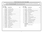
... 1 29 570807002 Outlet Tube 1 30 300946002 Oil Pump Assembly 1 31 531003001 Clamp 1 32 310983001 Oil Tank Cap Assembly 1 33 311072001 Oil Tank Assemlby (Inc. RYOBI RY40050 POLE SAW ATTACHMENT The model number will be found on a label attached to the motor housing. Always mention the model number in all correspondence regarding your POLE SAW ATTACHMENT or when ordering replacement parts. KEY PART NO. Hd 1 8 678356002 Adjustment Block 1 9 310987002 Chain 1 10 300961010 Guide Bar 1 11 580699010 Scabbard 1 12 670608002...
... 1 29 570807002 Outlet Tube 1 30 300946002 Oil Pump Assembly 1 31 531003001 Clamp 1 32 310983001 Oil Tank Cap Assembly 1 33 311072001 Oil Tank Assemlby (Inc. RYOBI RY40050 POLE SAW ATTACHMENT The model number will be found on a label attached to the motor housing. Always mention the model number in all correspondence regarding your POLE SAW ATTACHMENT or when ordering replacement parts. KEY PART NO. Hd 1 8 678356002 Adjustment Block 1 9 310987002 Chain 1 10 300961010 Guide Bar 1 11 580699010 Scabbard 1 12 670608002...

Parts Diagram
Page 4
RYOBI RY40050 POLE SAW ATTACHMENT MOTOR RED LEAD TO RED DOT • BOOM ASSEMBLY BLACK RED WIRING DIAGRAM 4
RYOBI RY40050 POLE SAW ATTACHMENT MOTOR RED LEAD TO RED DOT • BOOM ASSEMBLY BLACK RED WIRING DIAGRAM 4


