User Manual
Page 2
... repair any faulty workmanship, and either request service under this warranty or you by contacting a service representative at our option. warranty RYOBI® POWER TOOL - makes no warranties, representations or promises as to the quality or performance of its use more pleasant and... not apply to an Authorized Service Center. ADDITIONAL LIMITATIONS: Any implied warranties granted under normal usage and does not cover any defective part, at One World Technologies, Inc., P.O. is not responsible for direct, indirect, or incidental damages, so the above limitations and ...
... repair any faulty workmanship, and either request service under this warranty or you by contacting a service representative at our option. warranty RYOBI® POWER TOOL - makes no warranties, representations or promises as to the quality or performance of its use more pleasant and... not apply to an Authorized Service Center. ADDITIONAL LIMITATIONS: Any implied warranties granted under normal usage and does not cover any defective part, at One World Technologies, Inc., P.O. is not responsible for direct, indirect, or incidental damages, so the above limitations and ...
User Manual
Page 3
...Follow instructions for recommended accessories. The use only extension cords with approved ground connection that it was not designed for alignment of moving parts, binding of power and overheating. Use only a cord heavy enough to carry the current your hand and frees both hands to ...determine that are recommended when working order. REMOVE ADJUSTING KEYS AND WRENCHES. An undersized cord will draw. If in loss of moving parts. The smaller the gauge number, the heavier the cord. DRESS PROPERLY. Sharp blades minimize stalling and kickback. KEEP ...
...Follow instructions for recommended accessories. The use only extension cords with approved ground connection that it was not designed for alignment of moving parts, binding of power and overheating. Use only a cord heavy enough to carry the current your hand and frees both hands to ...determine that are recommended when working order. REMOVE ADJUSTING KEYS AND WRENCHES. An undersized cord will draw. If in loss of moving parts. The smaller the gauge number, the heavier the cord. DRESS PROPERLY. Sharp blades minimize stalling and kickback. KEEP ...

User Manual
Page 4
...grounding plugs and 3-pole receptacles that are tired. Instructions for and remove all adjustments are included with or without yellow stripes is moving parts during the same operation as in serious personal injury. To minimize risk of your saw . Through-sawing operations are doing and use... use blade washers or blade bolts that is green with the accessory. DOUBLE CHECK ALL SETUPS. Never use only identical replacement parts. Repair or replace a damaged or worn cord immediately. Do not operate tool when you are those in which the blade cuts completely ...
...grounding plugs and 3-pole receptacles that are tired. Instructions for and remove all adjustments are included with or without yellow stripes is moving parts during the same operation as in serious personal injury. To minimize risk of your saw . Through-sawing operations are doing and use... use blade washers or blade bolts that is green with the accessory. DOUBLE CHECK ALL SETUPS. Never use only identical replacement parts. Repair or replace a damaged or worn cord immediately. Do not operate tool when you are those in which the blade cuts completely ...
User Manual
Page 5
... instructions on the spreader/riving knife. THIS TOOL should have a straight edge to position and guide the work. NEVER stand or have any part of your body in line with the path of the saw table for which means using the table saw. ALWAYS TURN OFF SAW before...
... instructions on the spreader/riving knife. THIS TOOL should have a straight edge to position and guide the work. NEVER stand or have any part of your body in line with the path of the saw table for which means using the table saw. ALWAYS TURN OFF SAW before...
User Manual
Page 8
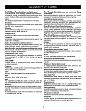
... operations. Push Blocks (jointer planers) Device used to prevent kickback. This aid helps keep the operator's hands well away from a block so the end (or part of the workpiece which produces a square, two-sided notch or trough in the workpiece. A push stick (not a push block) should be or has been cut...
... operations. Push Blocks (jointer planers) Device used to prevent kickback. This aid helps keep the operator's hands well away from a block so the end (or part of the workpiece which produces a square, two-sided notch or trough in the workpiece. A push stick (not a push block) should be or has been cut...
User Manual
Page 13
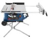
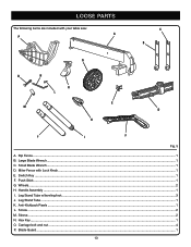
Handle Assembly...1 I. Small Blade Wrench...1 D. Leg Stand Tube w/leveling foot...3 J. Sleeve...2 N. Switch Key...1 F. Push Stick...1 G. Wheels...2 H. Hex Key...1 O. Blade Guard...1 13 Miter Fence with your table saw: A P c b g o n k l e m d h j i f Fig. 5 A. Leg Stand Tube...1 K. Screw...2 M. LOOSE PARTS The following items are included with Lock Knob...1 E. Rip Fence...1 B. Anti-Kickback Pawls...1 L. Carriage bolt and nut...4 P. Large Blade Wrench...1 C.
Handle Assembly...1 I. Small Blade Wrench...1 D. Leg Stand Tube w/leveling foot...3 J. Sleeve...2 N. Switch Key...1 F. Push Stick...1 G. Wheels...2 H. Hex Key...1 O. Blade Guard...1 13 Miter Fence with your table saw: A P c b g o n k l e m d h j i f Fig. 5 A. Leg Stand Tube...1 K. Screw...2 M. LOOSE PARTS The following items are included with Lock Knob...1 E. Rip Fence...1 B. Anti-Kickback Pawls...1 L. Carriage bolt and nut...4 P. Large Blade Wrench...1 C.
User Manual
Page 14
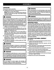
... cutting. Do not reach over or across the blade. NEVER operate the saw must be bolted securely using 5/16 in . Tighten all loose parts, and satisfactorily operated the tool. n Place a second flat washer then small spacer on the floor. WARNING: Do not connect to make sure...until assembly is misuse and could result in serious personal injury. Also, remove the foam blocks from the saw cabinet on the Loose Parts List are already assembled to possible serious personal injury. Four bolt holes have carefully inspected the tool, identified all four bolts securely. ...
... cutting. Do not reach over or across the blade. NEVER operate the saw must be bolted securely using 5/16 in . Tighten all loose parts, and satisfactorily operated the tool. n Place a second flat washer then small spacer on the floor. WARNING: Do not connect to make sure...until assembly is misuse and could result in serious personal injury. Also, remove the foam blocks from the saw cabinet on the Loose Parts List are already assembled to possible serious personal injury. Four bolt holes have carefully inspected the tool, identified all four bolts securely. ...

User Manual
Page 39
...; ADJUSTMENT SQUARE BLADE BOLT 45° BEVEL INDICATOR BEVEL HANDLE BEVEL LOCKING LEVER Fig. 57 39 NOTE: Make sure that the square contacts the flat part of the square and the saw have been set at 0° and 45° See Figures 56 - 57. NOTE: Make sure that the square contacts... the flat part of the saw blade should be parallel. If the blade is not perfectly vertical (0°): Unlock the bevel locking lever. Loosen the 0°...
...; ADJUSTMENT SQUARE BLADE BOLT 45° BEVEL INDICATOR BEVEL HANDLE BEVEL LOCKING LEVER Fig. 57 39 NOTE: Make sure that the square contacts the flat part of the square and the saw have been set at 0° and 45° See Figures 56 - 57. NOTE: Make sure that the square contacts... the flat part of the saw blade should be parallel. If the blade is not perfectly vertical (0°): Unlock the bevel locking lever. Loosen the 0°...

User Manual
Page 41
... tool. WARNING: Before performing any time let brake fluids, gasoline, petroleumbased products, penetrating oils, etc., come in contact with plastic parts. Most plastics are susceptible to damage from underneath the table and in position. Check the blade guard assembly. ... of the unit under normal operating conditions. The use any aerosol or petroleum solvents. MAINTENANCE WARNING: When servicing, use any other parts may create a hazard or cause product damage. Therefore, no further lubrication is in serious personal injury. 41 Chemicals can damage,...
... tool. WARNING: Before performing any time let brake fluids, gasoline, petroleumbased products, penetrating oils, etc., come in contact with plastic parts. Most plastics are susceptible to damage from underneath the table and in position. Check the blade guard assembly. ... of the unit under normal operating conditions. The use any aerosol or petroleum solvents. MAINTENANCE WARNING: When servicing, use any other parts may create a hazard or cause product damage. Therefore, no further lubrication is in serious personal injury. 41 Chemicals can damage,...
User Manual
Page 44
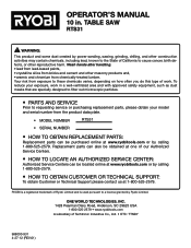
... masonry products and, • arsenic and chromium from the product data plate. • MODEL NUMBER RTS31 • SERIAL NUMBER • How to a license granted by calling 1-800-525-2579. RYOBI is used pursuant to obtain Replacement Parts: Replacement parts can be purchased online at 1-800-525-2579. Your risk from exposure to obtain Customer...
... masonry products and, • arsenic and chromium from the product data plate. • MODEL NUMBER RTS31 • SERIAL NUMBER • How to a license granted by calling 1-800-525-2579. RYOBI is used pursuant to obtain Replacement Parts: Replacement parts can be purchased online at 1-800-525-2579. Your risk from exposure to obtain Customer...

User Manual 4
Page 3
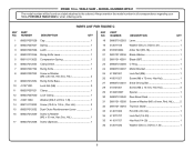
...Holder 2 2 089037012002 Screw (M6 x 25 mm, Pan Hd 6 25 089037012010 Screw (M4 x 10 mm, Rnd. PORTABLE TABLE SAW or when ordering parts. Triangle).......... 2 34 089037012713 Thoat Plate Assembly 1 12 410031002 Bolt (M6 x 40 mm 1 35 089037011004 Magnet 2 13 0134010306 Lever Holder 1 36 ... Table Lock Lever 1 42 089037012023 Auxiliary Table Indicator 1 20 410251017 Screw w/Washer (M6 x 12 mm, Rnd. RYOBI 10 in ., Pan Hd 6 31 410561013 Screw (M5 x 16 mm, Rnd. KEY PART NO. MODEL NUMBER RTS31 The model number will be found on a label attached to the cabinet.
...Holder 2 2 089037012002 Screw (M6 x 25 mm, Pan Hd 6 25 089037012010 Screw (M4 x 10 mm, Rnd. PORTABLE TABLE SAW or when ordering parts. Triangle).......... 2 34 089037012713 Thoat Plate Assembly 1 12 410031002 Bolt (M6 x 40 mm 1 35 089037011004 Magnet 2 13 0134010306 Lever Holder 1 36 ... Table Lock Lever 1 42 089037012023 Auxiliary Table Indicator 1 20 410251017 Screw w/Washer (M6 x 12 mm, Rnd. RYOBI 10 in ., Pan Hd 6 31 410561013 Screw (M5 x 16 mm, Rnd. KEY PART NO. MODEL NUMBER RTS31 The model number will be found on a label attached to the cabinet.

User Manual 4
Page 4
Always mention the model number in all correspondence regarding your 10 in . PORTABLE TABLE SAW or when ordering parts. RYOBI 10 in . MODEL NUMBER RTS31 The model number will be found on a label attached to the cabinet. NUMBER DESCRIPTION QTY 61 089037012906 Outer Front Rail Scale 1 62...:03) 4 Hd.)........ 4 0134010314 Block Rod 2 089037012029 Sliding Bar 2 0134010910 Locking Pin 2 0181010501 Quick Stop 2 0134010802 Lock Nut 2 9134015330201 Pinch Point Label 1 KEY PART NO. TABLE SAW - PARTS LIST FOR FIGURE A KEY NO. 46 47 48 49 50 51 52 53 54 55 56 57 58 59 60...
Always mention the model number in all correspondence regarding your 10 in . PORTABLE TABLE SAW or when ordering parts. RYOBI 10 in . MODEL NUMBER RTS31 The model number will be found on a label attached to the cabinet. NUMBER DESCRIPTION QTY 61 089037012906 Outer Front Rail Scale 1 62...:03) 4 Hd.)........ 4 0134010314 Block Rod 2 089037012029 Sliding Bar 2 0134010910 Locking Pin 2 0181010501 Quick Stop 2 0134010802 Lock Nut 2 9134015330201 Pinch Point Label 1 KEY PART NO. TABLE SAW - PARTS LIST FOR FIGURE A KEY NO. 46 47 48 49 50 51 52 53 54 55 56 57 58 59 60...

User Manual 4
Page 6
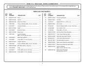
...089037012902 21 411071004 22 0134010236 23 412011117 24 0134010339 25 410134005 26 412042002 Cabinet 1 Screw (M8 x 40 mm, Half Rnd. MODEL NUMBER RTS31 The model number will be found on a label attached to the cabinet. Hd 2 Reinforcement Plate 1 Screw (M4 x 7 mm 4 ...Bevel Scale Label 1 Indicator 1 Screw w/Washer (M5 x 8 mm, Rnd. PARTS LIST FOR FIGURE B KEY PART NO. TABLE SAW - Soc. Always mention the model number in all correspondence regarding your 10 in . RYOBI 10 in . PORTABLE TABLE SAW or when ordering parts. Hd.)......... 4 Knob Ring 1 Wrench B 1 Wrench A 1 Wing Nut 1...
...089037012902 21 411071004 22 0134010236 23 412011117 24 0134010339 25 410134005 26 412042002 Cabinet 1 Screw (M8 x 40 mm, Half Rnd. MODEL NUMBER RTS31 The model number will be found on a label attached to the cabinet. Hd 2 Reinforcement Plate 1 Screw (M4 x 7 mm 4 ...Bevel Scale Label 1 Indicator 1 Screw w/Washer (M5 x 8 mm, Rnd. PARTS LIST FOR FIGURE B KEY PART NO. TABLE SAW - Soc. Always mention the model number in all correspondence regarding your 10 in . RYOBI 10 in . PORTABLE TABLE SAW or when ordering parts. Hd.)......... 4 Knob Ring 1 Wrench B 1 Wrench A 1 Wing Nut 1...
User Manual 4
Page 8
... 19 20 21 22 23 24 25 26 27 28 29 30 31 32 33 34 35 36 PART NUMBER DESCRIPTION QTY 089037012053 Lever 1 412011109 Washer (ID5.2 x OD24 x 2t 1 0181010804 Arbor Nut ... 089037012042 Rear Bevel Deck 1 089110113039 Screw w/Washer (M5 x 8 mm, Rnd. PORTABLE TABLE SAW or when ordering parts. Hd 2 Riving Knife Base 1 Lock Nut (M6 3 Clamp 1 Lock Clamp 1 13 412011030 14 089110110032 15 ...411071707 Lock Nut (1/4-20 1 411011707 Hex Nut (1/4-20 1 412011030 Washer (ID6.5 x OD16 x 1.5t 1 8 RYOBI 10 in ., Pan Hd 2 Dust Chute Reinforcement Lever 1 Screw w/Washer (M6 x 15 mm, Hex Soc....
... 19 20 21 22 23 24 25 26 27 28 29 30 31 32 33 34 35 36 PART NUMBER DESCRIPTION QTY 089037012053 Lever 1 412011109 Washer (ID5.2 x OD24 x 2t 1 0181010804 Arbor Nut ... 089037012042 Rear Bevel Deck 1 089110113039 Screw w/Washer (M5 x 8 mm, Rnd. PORTABLE TABLE SAW or when ordering parts. Hd 2 Riving Knife Base 1 Lock Nut (M6 3 Clamp 1 Lock Clamp 1 13 412011030 14 089110110032 15 ...411071707 Lock Nut (1/4-20 1 411011707 Hex Nut (1/4-20 1 412011030 Washer (ID6.5 x OD16 x 1.5t 1 8 RYOBI 10 in ., Pan Hd 2 Dust Chute Reinforcement Lever 1 Screw w/Washer (M6 x 15 mm, Hex Soc....
User Manual 4
Page 9
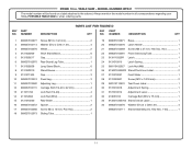
...Dust Chute 1 58 410331003 Screw w/Washer (M6 x 10 mm, Rnd. PORTABLE TABLE SAW or when ordering parts. MODEL NUMBER RTS31 The model number will be found on a label attached to the cabinet. Hd 2 69 089037007700 Blade Guard ...0134010503 Plate 1 52 410109019 Screw (M6 x 20 mm, Pan Hd 1 53 089037012049 Screw (M6 x 12 mm, Special 1 KEY PART NO. Hd.)........ 2 59 0134010226 Dust Chute Cover 1 60 410191003 Screw (M4 x 12 mm 2 61 089037012709 Anti-Kick Back Pawl...1 68 089037012103 Screw w/Washer (M6 x 15 mm, Hex Soc. TABLE SAW - RYOBI 10 in. Key Nos. 62-67 1 9
...Dust Chute 1 58 410331003 Screw w/Washer (M6 x 10 mm, Rnd. PORTABLE TABLE SAW or when ordering parts. MODEL NUMBER RTS31 The model number will be found on a label attached to the cabinet. Hd 2 69 089037007700 Blade Guard ...0134010503 Plate 1 52 410109019 Screw (M6 x 20 mm, Pan Hd 1 53 089037012049 Screw (M6 x 12 mm, Special 1 KEY PART NO. Hd.)........ 2 59 0134010226 Dust Chute Cover 1 60 410191003 Screw (M4 x 12 mm 2 61 089037012709 Anti-Kick Back Pawl...1 68 089037012103 Screw w/Washer (M6 x 15 mm, Hex Soc. TABLE SAW - RYOBI 10 in. Key Nos. 62-67 1 9
User Manual 4
Page 11
.... PORTABLE TABLE SAW or when ordering parts. NUMBER DESCRIPTION PARTS LIST FOR FIGURE D QTY KEY PART NO. Hd 1 4 0131020209 Short Stand Block 6 22 089037012081 Front Stand Leg Tube 1 5 0131020217 Cap 2 23 0134110325R Latch 1 6 089037012075 Rear Stand Leg Tube 1...089037012076 Washer (D13.5 x D28 x 2t 4 17 089037012068 Screw (M4 x 10 mm, Pan Hd 2 089037012711 Stand Assembly (Inc. RYOBI 10 in . Key Nos. 1-35 1 18 089037012073 Sliding Tube 1 11 MODEL NUMBER RTS31 The model number will be found on a label attached to the cabinet. Always mention the model number in all...
.... PORTABLE TABLE SAW or when ordering parts. NUMBER DESCRIPTION PARTS LIST FOR FIGURE D QTY KEY PART NO. Hd 1 4 0131020209 Short Stand Block 6 22 089037012081 Front Stand Leg Tube 1 5 0131020217 Cap 2 23 0134110325R Latch 1 6 089037012075 Rear Stand Leg Tube 1...089037012076 Washer (D13.5 x D28 x 2t 4 17 089037012068 Screw (M4 x 10 mm, Pan Hd 2 089037012711 Stand Assembly (Inc. RYOBI 10 in . Key Nos. 1-35 1 18 089037012073 Sliding Tube 1 11 MODEL NUMBER RTS31 The model number will be found on a label attached to the cabinet. Always mention the model number in all...

User Manual 4
Page 12
MODEL NUMBER RTS31 4 6 3 7 8 5 9 FIGURE E KEY PART NO. NUMBER DESCRIPTION QTY KEY PART NO. Key Nos. 1-9 1 12 TABLE SAW - NUMBER DESCRIPTION QTY 1 089037012095 Cap 2 6 0181010209 Miter Knob 1 2 0181010208-58 Miter Indicator 1 7 412011051 Washer (ID8 x OD16 x 1.5t 1 3 0134011801 Miter Rod 1 8 0181010210 Miter Base 1 4 089037012113 Locator Pin 1 9 410011717 Screw (5/16-18 x 3-1/4 in., Hex Hd 1 5 410451702 Screw (3/16 in . 2 1 RYOBI 10 in 2 089037012708 Miter Fence Assembly (Inc.
MODEL NUMBER RTS31 4 6 3 7 8 5 9 FIGURE E KEY PART NO. NUMBER DESCRIPTION QTY KEY PART NO. Key Nos. 1-9 1 12 TABLE SAW - NUMBER DESCRIPTION QTY 1 089037012095 Cap 2 6 0181010209 Miter Knob 1 2 0181010208-58 Miter Indicator 1 7 412011051 Washer (ID8 x OD16 x 1.5t 1 3 0134011801 Miter Rod 1 8 0181010210 Miter Base 1 4 089037012113 Locator Pin 1 9 410011717 Screw (5/16-18 x 3-1/4 in., Hex Hd 1 5 410451702 Screw (3/16 in . 2 1 RYOBI 10 in 2 089037012708 Miter Fence Assembly (Inc.

User Manual 4
Page 13
Key Nos 1-17)......... 1 13 MODEL NUMBER RTS31 7 1 23 4 2 6 10 11 12 9 17 8 2 13 14 15 16 5 FIGURE F KEY PART NO. RYOBI 10 in 4 Crank Ring 2 Crank Shaft 1 Rip Fence Assembly (Inc. TABLE SAW - NUMBER DESCRIPTION QTY 1 411071001 Lock Nut (M6 1 2 412011030... x 15 mm, Hex Hd 2 9 412011115 Washer (ID16 x OD25 x 1.5t 2 KEY NO. 10 11 12 13 14 15 16 17 PART NUMBER DESCRIPTION QTY 0131020209 410331008 089037012065 089037012066 089037012067 410101713 0121010210 0134010241 089037012707 Fence Slider 1 Screw w/Washer (M4 x 10 mm, Pan Hd.)......... 1 Fence Indicator...
Key Nos 1-17)......... 1 13 MODEL NUMBER RTS31 7 1 23 4 2 6 10 11 12 9 17 8 2 13 14 15 16 5 FIGURE F KEY PART NO. RYOBI 10 in 4 Crank Ring 2 Crank Shaft 1 Rip Fence Assembly (Inc. TABLE SAW - NUMBER DESCRIPTION QTY 1 411071001 Lock Nut (M6 1 2 412011030... x 15 mm, Hex Hd 2 9 412011115 Washer (ID16 x OD25 x 1.5t 2 KEY NO. 10 11 12 13 14 15 16 17 PART NUMBER DESCRIPTION QTY 0131020209 410331008 089037012065 089037012066 089037012067 410101713 0121010210 0134010241 089037012707 Fence Slider 1 Screw w/Washer (M4 x 10 mm, Pan Hd.)......... 1 Fence Indicator...

User Manual 4
Page 14
.... TABLE SAW - 21 16 RYOBI 10 in 1 10 0134010202 Baffle 1 20 441010012 O-Ring 1 11 089110110026 Ball Bearing (6200 ZZ C3 1 21 089037012703 Arbor Assembly 1 089037012702 Motor Assembly (Inc Key Nos. 1-21 1 14 MODEL NUMBER RTS31 14 15 1 3 17 18 7 8 10 12 11 19 20 13 2 4 5 6 9 FIGURE G KEY PART NO. Key Nos. 11 and...
.... TABLE SAW - 21 16 RYOBI 10 in 1 10 0134010202 Baffle 1 20 441010012 O-Ring 1 11 089110110026 Ball Bearing (6200 ZZ C3 1 21 089037012703 Arbor Assembly 1 089037012702 Motor Assembly (Inc Key Nos. 1-21 1 14 MODEL NUMBER RTS31 14 15 1 3 17 18 7 8 10 12 11 19 20 13 2 4 5 6 9 FIGURE G KEY PART NO. Key Nos. 11 and...


