Operation Manual
Page 5
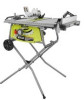
... parallel to the rear and sides of the saw table for wide or long workpieces. AVOID KICKBACKS (work thrown back toward you loan someone this manual or addendums. Use of accessories that is pushed all through sawing. Instructions for safe use of accessories are not...61550; THIS TOOL should have any operation freehand. d) Use a push stick when required. d) Not releasing the work using the table saw. ALWAYS TURN OFF SAW before it , to avoid accidental starting when reconnecting to move into the cutting tool. USE ONLY RECOMMENDED ACCESSORIES listed ...
... parallel to the rear and sides of the saw table for wide or long workpieces. AVOID KICKBACKS (work thrown back toward you loan someone this manual or addendums. Use of accessories that is pushed all through sawing. Instructions for safe use of accessories are not...61550; THIS TOOL should have any operation freehand. d) Use a push stick when required. d) Not releasing the work using the table saw. ALWAYS TURN OFF SAW before it , to avoid accidental starting when reconnecting to move into the cutting tool. USE ONLY RECOMMENDED ACCESSORIES listed ...
Operation Manual
Page 8
... guided by the blade. Worktable Surface where the workpiece rests while performing a cutting, drilling, planing, or sanding operation. 8 - Featherboard (table saws) A device used . Kickback A hazard that serves as a guide for drilling large holes accurately or for narrow ripping operations, if a jig...angle. Revolutions Per Minute (RPM) The number of turns completed by guiding it applies to the miter gauge groove. Resaw (table saws and band saws) A cutting operation to reduce the thickness of the blade. A small hole drilled in front of the workpiece to feed...
... guided by the blade. Worktable Surface where the workpiece rests while performing a cutting, drilling, planing, or sanding operation. 8 - Featherboard (table saws) A device used . Kickback A hazard that serves as a guide for drilling large holes accurately or for narrow ripping operations, if a jig...angle. Revolutions Per Minute (RPM) The number of turns completed by guiding it applies to the miter gauge groove. Resaw (table saws and band saws) A cutting operation to reduce the thickness of the blade. A small hole drilled in front of the workpiece to feed...
Operation Manual
Page 10
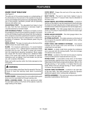
... blade provided with the locking handle. Your local dealer can provide you with the bevel locking lever. This lever, placed just under the saw table, this warning could result in the grooves on the rip fence. Keeps the cord out of the blade. A vacuum hose may be .... OUTFEED SUPPORT - Convenient storage for the push stick and wrenches is recommended that you are available for rip cuts. English FEATURES KNOW YOUR TABLE SAW See Figure 2. For maximum performance, it is raised and lowered with all operating features and safety rules. WARNING: Do not use this tool...
... blade provided with the locking handle. Your local dealer can provide you with the bevel locking lever. This lever, placed just under the saw table, this warning could result in the grooves on the rip fence. Keeps the cord out of the blade. A vacuum hose may be .... OUTFEED SUPPORT - Convenient storage for the push stick and wrenches is recommended that you are available for rip cuts. English FEATURES KNOW YOUR TABLE SAW See Figure 2. For maximum performance, it is raised and lowered with all operating features and safety rules. WARNING: Do not use this tool...
Operation Manual
Page 13
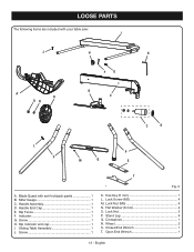
Handle Assembly 1 D. Screw 1 H. Lock Nut (M5 4 N. Lock Nut 2 P. Crosspiece 1 R. Closed End Wrench 1 T. English Screw 1 Fig. 5 K. Rip indicator end cap 1 I J H K FG A R ON B E C D L P P M Q S T A. Hex Key (5 mm 1 L. Blade Guard with your table saw: I . LOOSE PARTS The following items are included with anti-kickback pawls 1 B. Miter Gauge 1 C. Rip Fence 1 F. Stand Leg 4 Q. Flat Washer (8 mm 4 O. Wheel 2 S. Sliding Table Assembly 1 J. Handle End Cap 1 E. Indicator 1 G. Lock Screw (M5 4 M. Open End Wrench 1 13 -
Handle Assembly 1 D. Screw 1 H. Lock Nut (M5 4 N. Lock Nut 2 P. Crosspiece 1 R. Closed End Wrench 1 T. English Screw 1 Fig. 5 K. Rip indicator end cap 1 I J H K FG A R ON B E C D L P P M Q S T A. Hex Key (5 mm 1 L. Blade Guard with your table saw: I . LOOSE PARTS The following items are included with anti-kickback pawls 1 B. Miter Gauge 1 C. Rip Fence 1 F. Stand Leg 4 Q. Flat Washer (8 mm 4 O. Wheel 2 S. Sliding Table Assembly 1 J. Handle End Cap 1 E. Indicator 1 G. Lock Screw (M5 4 M. Open End Wrench 1 13 -

Operation Manual
Page 14
...61550; Do not discard the packing material until assembly is factory set for assistance. WARNING: To avoid serious personal injury, always make sure the table saw is noted, secure the workbench to come closer than 3 in a hazardous condition leading to a workbench or an approved leg stand. NOTE: This... work bench, insert bolts that are not assembled to make sure that may have been improperly assembled could result in . MOUNTING HOLES The table saw 's frame for this leg stand with your legs, not your back, and get help . Four bolt holes have carefully inspected the tool...
...61550; Do not discard the packing material until assembly is factory set for assistance. WARNING: To avoid serious personal injury, always make sure the table saw is noted, secure the workbench to come closer than 3 in a hazardous condition leading to a workbench or an approved leg stand. NOTE: This... work bench, insert bolts that are not assembled to make sure that may have been improperly assembled could result in . MOUNTING HOLES The table saw 's frame for this leg stand with your legs, not your back, and get help . Four bolt holes have carefully inspected the tool...

Operation Manual
Page 18
... inner stand support bracket and lift it until it locks. Set your right foot against the foot of the saw. To close (tear down the saw frame. Hold the saw table and grasp the upper saw upright. Hook the latch into the crosspiece and push the latch back until it while you push downward on... in the locked position. NOTE: Use the cord wrap on the end of the saw to keep the cord out of the table saw, place your left foot against the saw leg to steady it meets the saw . SET-UP TEAR-DOWN 18 - Allow both leg sections so that the crosspiece meets the latch. English...
... inner stand support bracket and lift it until it locks. Set your right foot against the foot of the saw. To close (tear down the saw frame. Hold the saw table and grasp the upper saw upright. Hook the latch into the crosspiece and push the latch back until it while you push downward on... in the locked position. NOTE: Use the cord wrap on the end of the saw to keep the cord out of the table saw, place your left foot against the saw leg to steady it meets the saw . SET-UP TEAR-DOWN 18 - Allow both leg sections so that the crosspiece meets the latch. English...
Operation Manual
Page 23
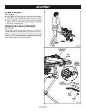
... use the storage area, insert the tip of the push stick into the slot until the leg stand and saw are balanced on the wheels. Push the saw to the desired location then either open the leg stand for the push stick is located on top of the rip fence... 20. Holding the leg stand firmly, pull the leg stand toward you until it clicks into place. STORING TABLE SAW ACCESSORIES See Figure 21. Additional storage for immediate saw operation or store the saw table, secured by a wing nut. PUSH STICK STORAGE RIP FENCE Fig. 20 BLADE WRENCH STORAGE 23 - English BLADE WRENCHES...
... use the storage area, insert the tip of the push stick into the slot until the leg stand and saw are balanced on the wheels. Push the saw to the desired location then either open the leg stand for the push stick is located on top of the rip fence... 20. Holding the leg stand firmly, pull the leg stand toward you until it clicks into place. STORING TABLE SAW ACCESSORIES See Figure 21. Additional storage for immediate saw operation or store the saw table, secured by a wing nut. PUSH STICK STORAGE RIP FENCE Fig. 20 BLADE WRENCH STORAGE 23 - English BLADE WRENCHES...

Operation Manual
Page 24
...into a matching outlet that a careless fraction of kickback. 24 - Refer to the Electrical section in serious personal injury. BASIC OPERATION OF THE TABLE SAW The 3-prong plug must be ready to do so. Never stand directly in line with push sticks and/or push blocks. Remember that is ...outlet installed by any action that pinches the blade in the workpiece Twisting the wood while making and woodworking NOTE: This table saw into knots or nails in the wood such as: Making a cut Not following correct operating procedures Misusing the...
...into a matching outlet that a careless fraction of kickback. 24 - Refer to the Electrical section in serious personal injury. BASIC OPERATION OF THE TABLE SAW The 3-prong plug must be ready to do so. Never stand directly in line with push sticks and/or push blocks. Remember that is ...outlet installed by any action that pinches the blade in the workpiece Twisting the wood while making and woodworking NOTE: This table saw into knots or nails in the wood such as: Making a cut Not following correct operating procedures Misusing the...

Operation Manual
Page 28
... position. GULLET TO DECREASE ANGLE HEIGHT/BEVEL ADJUSTING HANDWHEEL 28 - Retighten the screw. If the bevel indicator is not at zero when the saw has a rack and pinion bevel control that the outer points of the blade are below the top surface. Turn the bevel lock...the workpiece by turning bevel lock lever all the way to 45° bevel angle. Tighten bevel control by turning the handwheel counterclockwise. This table saw blade is securely tightened. Turn it at 0° on the bevel scale. OPERATION TO CHANGE BLADE DEPTH See Figures 28 - 29. NOTE: A ...
... position. GULLET TO DECREASE ANGLE HEIGHT/BEVEL ADJUSTING HANDWHEEL 28 - Retighten the screw. If the bevel indicator is not at zero when the saw has a rack and pinion bevel control that the outer points of the blade are below the top surface. Turn the bevel lock...the workpiece by turning bevel lock lever all the way to 45° bevel angle. Tighten bevel control by turning the handwheel counterclockwise. This table saw blade is securely tightened. Turn it at 0° on the bevel scale. OPERATION TO CHANGE BLADE DEPTH See Figures 28 - 29. NOTE: A ...
Operation Manual
Page 30
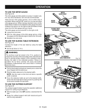
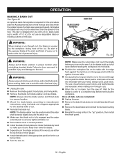
... support slides to give the operator additional support for cutting long workpieces. With the table saw in the extended position. Increase the length of the workpiece when using the table extension. Set the rip fence to position the rip fence correctly will cause inaccurate workpiece...When making a beveled cross cut , you to provide proper support of the saw table by pushing the levers back towards the saw . Grasp the outfeed support with the back lever. Slide the table extension to the desired width. OPERATION TO USE THE MITER GAUGE See Figure ...
... support slides to give the operator additional support for cutting long workpieces. With the table saw in the extended position. Increase the length of the workpiece when using the table extension. Set the rip fence to position the rip fence correctly will cause inaccurate workpiece...When making a beveled cross cut , you to provide proper support of the saw table by pushing the levers back towards the saw . Grasp the outfeed support with the back lever. Slide the table extension to the desired width. OPERATION TO USE THE MITER GAUGE See Figure ...
Operation Manual
Page 32
...hand farthest from the blade should not be saved on scrap wood first. If a suitable location can not be found, then the saw should be placed on table saw stand could result in this tool. Your local library has many books on the workpiece. When the cut operations. The ... check all mentioned in personal injury. SWITCH OFF SWITCH ON Fig. 38 WARNING: Do not use . Failure to handle and properly support the table saw stand is on the miter gauge and feed the workpiece into the blade. NOTE: The hand closest to full speed before use blades rated less...
...hand farthest from the blade should not be saved on scrap wood first. If a suitable location can not be found, then the saw should be placed on table saw stand could result in this tool. Your local library has many books on the workpiece. When the cut operations. The ... check all mentioned in personal injury. SWITCH OFF SWITCH ON Fig. 38 WARNING: Do not use . Failure to handle and properly support the table saw stand is on the miter gauge and feed the workpiece into the blade. NOTE: The hand closest to full speed before use blades rated less...
Operation Manual
Page 34
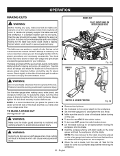
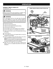
... FRONT, BELOW THE TABLE SAW BEVEL LOCKING LEVER TO TIGHTEN WARNING: The miter gauge must be placed on the workpiece. When the cut is installed and working properly to avoid possible serious injury. WARNING: Make sure the blade guard assembly is made, turn the saw on. ...on the right side of the blade before removing the workpiece. NOTE: The hand closest to a complete stop before turning on the saw. Turn the saw off. OPERATION MAKING A BEVEL CROSS CUT See Figures 42 - 43. BLADE ANGLED TO LOOSEN HEIGHT/BEVEL ADJUSTING HANDWHEEL BEVEL CROSS CUT...
... FRONT, BELOW THE TABLE SAW BEVEL LOCKING LEVER TO TIGHTEN WARNING: The miter gauge must be placed on the workpiece. When the cut is installed and working properly to avoid possible serious injury. WARNING: Make sure the blade guard assembly is made, turn the saw on. ...on the right side of the blade before removing the workpiece. NOTE: The hand closest to a complete stop before turning on the saw. Turn the saw off. OPERATION MAKING A BEVEL CROSS CUT See Figures 42 - 43. BLADE ANGLED TO LOOSEN HEIGHT/BEVEL ADJUSTING HANDWHEEL BEVEL CROSS CUT...
Operation Manual
Page 39
... during most of this tool. Never push a small piece of wood into the blade. Position the workpiece flat on the table with the retailer where the table saw table. Use a push block or push stick to move the wood through cut, the blade is made . Turn ...the saw on the saw off. English Failure to manufacturer instructions, using the blade and chippers appropriate for the cut . WARNING: Always use a push stick...
... during most of this tool. Never push a small piece of wood into the blade. Position the workpiece flat on the table with the retailer where the table saw table. Use a push block or push stick to move the wood through cut, the blade is made . Turn ...the saw on the saw off. English Failure to manufacturer instructions, using the blade and chippers appropriate for the cut . WARNING: Always use a push stick...
Parts Diagram
Page 2
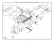
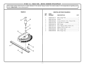
RYOBI 10 in. MODEL NUMBER RTS22/RTS22T 44 46 45 39 1 6 7 48 33 2 32 34 27 3 41 38 39 40 35 36 43 42 40 41 5 37 26 11 25 19 18 24 23 21 26 28 14 27 25 26 5 9 20 21 19 18 15 10 16 17 13 22 27 34 33 35 32 28 29 30 31 27 12 FIGURE A FIGURE B 2 TABLE SAW -
RYOBI 10 in. MODEL NUMBER RTS22/RTS22T 44 46 45 39 1 6 7 48 33 2 32 34 27 3 41 38 39 40 35 36 43 42 40 41 5 37 26 11 25 19 18 24 23 21 26 28 14 27 25 26 5 9 20 21 19 18 15 10 16 17 13 22 27 34 33 35 32 28 29 30 31 27 12 FIGURE A FIGURE B 2 TABLE SAW -

Parts Diagram
Page 3
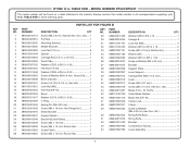
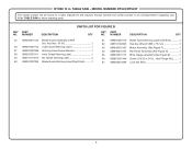
...Hd.).....2 Not Shown: 089240015199 Optional Dado Throat Plate Assembly (Inc. NUMBER DESCRIPTION QTY 1 089240015704 Throat Plate Assembly (Inc. Soc. RYOBI 10 in . Always mention the model number in all correspondence regarding your 10 in . Hd 4 27 089110101014 Screw (#10 ...089240015906 Styrofoam Removal Warning Label 995000231 Operator's Manual (089240052802) 1-28-20 (Rev:05) 3 TABLE SAW - NUMBER DESCRIPTION QTY KEY PART NO. MODEL NUMBER RTS22/RTS22T The model number will be found on a label attached to the cabinet. Key Nos....
...Hd.).....2 Not Shown: 089240015199 Optional Dado Throat Plate Assembly (Inc. NUMBER DESCRIPTION QTY 1 089240015704 Throat Plate Assembly (Inc. Soc. RYOBI 10 in . Always mention the model number in all correspondence regarding your 10 in . Hd 4 27 089110101014 Screw (#10 ...089240015906 Styrofoam Removal Warning Label 995000231 Operator's Manual (089240052802) 1-28-20 (Rev:05) 3 TABLE SAW - NUMBER DESCRIPTION QTY KEY PART NO. MODEL NUMBER RTS22/RTS22T The model number will be found on a label attached to the cabinet. Key Nos....
Parts Diagram
Page 5
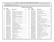
MODEL NUMBER RTS22/RTS22T The model number will be found on a label attached to the cabinet. TABLE SAW or when ordering parts. NUMBER DESCRIPTION QTY 1 089240015112 Screw (M6 x 8 mm, Special Hex. Soc. Hd 2 50 089037007023 Riving Knife Base... Screw (M6 x 15 mm, Hex Soc. Always mention the model number in all correspondence regarding your 10 in . PARTS LIST FOR FIGURE B KEY PART NO. RYOBI 10 in . Hd.)......1 2 089037007012 Pull Rod 1 3 089240015045 Mounting Bracket 1 4 089240015035 Middle Bracket 1 29 089240015108 Washer (OD8 x ID4 x 1t 1 30...
MODEL NUMBER RTS22/RTS22T The model number will be found on a label attached to the cabinet. TABLE SAW or when ordering parts. NUMBER DESCRIPTION QTY 1 089240015112 Screw (M6 x 8 mm, Special Hex. Soc. Hd 2 50 089037007023 Riving Knife Base... Screw (M6 x 15 mm, Hex Soc. Always mention the model number in all correspondence regarding your 10 in . PARTS LIST FOR FIGURE B KEY PART NO. RYOBI 10 in . Hd.)......1 2 089037007012 Pull Rod 1 3 089240015045 Mounting Bracket 1 4 089240015035 Middle Bracket 1 29 089240015108 Washer (OD8 x ID4 x 1t 1 30...
Parts Diagram
Page 6
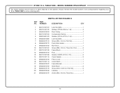
MODEL NUMBER RTS22/RTS22T The model number will be found on a label attached to the cabinet. Key Nos. 56-61 1 56 089037007912 Outer Guard Warning Label 1 57 089037007908 ... Motor Assembly (See Figure F 1 64 089240015155 Rip Fence Assembly (See Figure D 1 65 089240015174 Miter Gauge Assembly (See Figure E 1 66 080015001446 Screw (1/4-20 x 3/4 in . TABLE SAW or when ordering parts. RYOBI 10 in ., Hex Flange Hd.)..........1 67 089240015089 Lock Nut (M4 1 6 PARTS LIST FOR FIGURE B KEY PART NO. Always mention the model number in...
MODEL NUMBER RTS22/RTS22T The model number will be found on a label attached to the cabinet. Key Nos. 56-61 1 56 089037007912 Outer Guard Warning Label 1 57 089037007908 ... Motor Assembly (See Figure F 1 64 089240015155 Rip Fence Assembly (See Figure D 1 65 089240015174 Miter Gauge Assembly (See Figure E 1 66 080015001446 Screw (1/4-20 x 3/4 in . TABLE SAW or when ordering parts. RYOBI 10 in ., Hex Flange Hd.)..........1 67 089240015089 Lock Nut (M4 1 6 PARTS LIST FOR FIGURE B KEY PART NO. Always mention the model number in...
Parts Diagram
Page 8
RYOBI 10 in . PARTS LIST FOR FIGURE C KEY PART NO. x 1t 1 Compression ... Hd 2 Cord Clamp 1 Screw (M4 x 12 mm, Round Hd 3 Reinforcement Plate 1 Front Panel Assembly (Inc. Key No. 50, RTS22)..... 1 Dust Chute Assy. (Inc. NUMBER DESCRIPTION QTY 1 089240015001 2 089240015002 3 089240016119 4 089240015004 5 089240015114 6 089240015115 7 080015001496 8 089240015003 ... Power Cord Assembly (Inc. Hd 1 Screw (M6 x 20 mm, Truss Soc. TABLE SAW - TABLE SAW or when ordering parts. NUMBER DESCRIPTION QTY KEY PART NO. Hd 1 Screw (M6 x 33 mm, Soc.
RYOBI 10 in . PARTS LIST FOR FIGURE C KEY PART NO. x 1t 1 Compression ... Hd 2 Cord Clamp 1 Screw (M4 x 12 mm, Round Hd 3 Reinforcement Plate 1 Front Panel Assembly (Inc. Key No. 50, RTS22)..... 1 Dust Chute Assy. (Inc. NUMBER DESCRIPTION QTY 1 089240015001 2 089240015002 3 089240016119 4 089240015004 5 089240015114 6 089240015115 7 080015001496 8 089240015003 ... Power Cord Assembly (Inc. Hd 1 Screw (M6 x 20 mm, Truss Soc. TABLE SAW - TABLE SAW or when ordering parts. NUMBER DESCRIPTION QTY KEY PART NO. Hd 1 Screw (M6 x 33 mm, Soc.
Parts Diagram
Page 10
...089240015170 Screw (8-32 x 8.5 mm, Flat Hd 2 20 089240015168 Indicator 1 21 089240015197 Screw (M4 x 10 mm, Truss Hd 1 10 MODEL NUMBER RTS22/RTS22T The model number will be found on a label attached to the cabinet. PARTS LIST FOR FIGURE D KEY PART NO. NUMBER DESCRIPTION QTY 1 ...M4 x 12 mm, Flat Hd 1 8 089240015172 Push Stick Holder 1 9 089240015162 Rip Fence 1 10 089110101107 Screw (M6 x 15 mm, Truss Soc. TABLE SAW or when ordering parts. Always mention the model number in all correspondence regarding your 10 in . TABLE SAW - RYOBI 10 in .
...089240015170 Screw (8-32 x 8.5 mm, Flat Hd 2 20 089240015168 Indicator 1 21 089240015197 Screw (M4 x 10 mm, Truss Hd 1 10 MODEL NUMBER RTS22/RTS22T The model number will be found on a label attached to the cabinet. PARTS LIST FOR FIGURE D KEY PART NO. NUMBER DESCRIPTION QTY 1 ...M4 x 12 mm, Flat Hd 1 8 089240015172 Push Stick Holder 1 9 089240015162 Rip Fence 1 10 089110101107 Screw (M6 x 15 mm, Truss Soc. TABLE SAW or when ordering parts. Always mention the model number in all correspondence regarding your 10 in . TABLE SAW - RYOBI 10 in .
Parts Diagram
Page 11
... MODEL NUMBER RTS22/RTS22T The model number will be found on a label attached to the cabinet. NUMBER DESCRIPTION QTY 1 089240015177 Miter Gauge Rod 1 2 080015001563 Pointer 1 3 080015001662 Screw (3/16-24 x 1/4 in . TABLE SAW or when ...ordering parts. Hd 1 4 089037007078 Screw (M4 X 14.8 MM 1 5 089040002706 Miter Gauge 1 6 080015001475 Nylon Washer (OD16 x ID6.5 x 2t 1 7 080015001560 Washer (OD16 x ID6.5 x 2t 1 8 089040002005 Miter Gauge Knob 1 9 089040002006 Miter Gauge Cap 1 1 4 3 2 11 TABLE SAW - RYOBI 10...
... MODEL NUMBER RTS22/RTS22T The model number will be found on a label attached to the cabinet. NUMBER DESCRIPTION QTY 1 089240015177 Miter Gauge Rod 1 2 080015001563 Pointer 1 3 080015001662 Screw (3/16-24 x 1/4 in . TABLE SAW or when ...ordering parts. Hd 1 4 089037007078 Screw (M4 X 14.8 MM 1 5 089040002706 Miter Gauge 1 6 080015001475 Nylon Washer (OD16 x ID6.5 x 2t 1 7 080015001560 Washer (OD16 x ID6.5 x 2t 1 8 089040002005 Miter Gauge Knob 1 9 089040002006 Miter Gauge Cap 1 1 4 3 2 11 TABLE SAW - RYOBI 10...

