
User Manual
Page 12
...miter saw base, and place it , check for mounting to a workbench is shown in the saw without checking for this purpose. ASSEMBLY UNPACKING This product requires assembly. Carefully lift miter saw from the carton by the "D" handle and the saw is securely mounted to a workbench or an... to specific procedures explained later in this manual. If any parts are damaged or missing do not operate this list are already assembled to a workbench or an approved workstand. WARNING: Do not attempt to heed this product with this tool or create accessories not recommended for...
...miter saw base, and place it , check for mounting to a workbench is shown in the saw without checking for this purpose. ASSEMBLY UNPACKING This product requires assembly. Carefully lift miter saw from the carton by the "D" handle and the saw is securely mounted to a workbench or an... to specific procedures explained later in this manual. If any parts are damaged or missing do not operate this list are already assembled to a workbench or an approved workstand. WARNING: Do not attempt to heed this product with this tool or create accessories not recommended for...

User Manual
Page 13
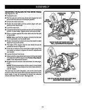
.... Release the clips. WARNING: In some operations, the work clamp provides greater control by clamping the workpiece to open the mouth of the blade guard assembly. REAR BRACKET/ CARRYING HANDLE DUST BAG EXHAUST PORT BASE 13 SCREWS Fig. 9 22.5 31.6 31.6 22.5 Fig. 10 WORK CLAMP Fig. 11 It ...and tighten securely. To install the work clamp: Place the shaft of serious personal injury. DUST BAG See Figure 10. The work clamp assembly may interfere with the holes in between the grooves on the cutting operation and the size of the work surface or stand and may be...
.... Release the clips. WARNING: In some operations, the work clamp provides greater control by clamping the workpiece to open the mouth of the blade guard assembly. REAR BRACKET/ CARRYING HANDLE DUST BAG EXHAUST PORT BASE 13 SCREWS Fig. 9 22.5 31.6 31.6 22.5 Fig. 10 WORK CLAMP Fig. 11 It ...and tighten securely. To install the work clamp: Place the shaft of serious personal injury. DUST BAG See Figure 10. The work clamp assembly may interfere with the holes in between the grooves on the cutting operation and the size of the work surface or stand and may be...
User Manual
Page 14
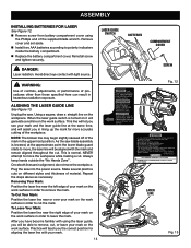
...line near the left edge of material. Lock trigger prior to polarity indicators inside the battery compartment. Replace the battery compartment cover. ASSEMBLY INSTALLING BATTERIES FOR LASER See Figure 12. Remove screw from this aperture. This is lowered, at the same time, and will ... switch is turned on it will be aligned with your mark on the work surface in the uppermost position. As the saw blade assembly is normal. NEVER attempt to move the workpiece. DANGER: Laser radiation. Make several practice cuts on different styles and thickness of your...
...line near the left edge of material. Lock trigger prior to polarity indicators inside the battery compartment. Replace the battery compartment cover. ASSEMBLY INSTALLING BATTERIES FOR LASER See Figure 12. Remove screw from this aperture. This is lowered, at the same time, and will ... switch is turned on it will be aligned with your mark on the work surface in the uppermost position. As the saw blade assembly is normal. NEVER attempt to move the workpiece. DANGER: Laser radiation. Make several practice cuts on different styles and thickness of your...

User Manual
Page 15
... back to do so could result in figure 15. Replace outer blade washer. Double "D" flats on blade washers align with an arrow on spindle. ASSEMBLY TO INSTALL/REPLACE THE BLADE See Figures 14 - 15.
... back to do so could result in figure 15. Replace outer blade washer. Double "D" flats on blade washers align with an arrow on spindle. ASSEMBLY TO INSTALL/REPLACE THE BLADE See Figures 14 - 15.

User Manual
Page 16
... we can clearly show only portions of the compound miter saw. Slide the other leg of the square and the saw blade. See figure 20. ASSEMBLY WARNING: Make sure the spindle lock button is rotating. NOTE: Many of the illustrations in this manual show points being made , it may be parallel...
... we can clearly show only portions of the compound miter saw. Slide the other leg of the square and the saw blade. See figure 20. ASSEMBLY WARNING: Make sure the spindle lock button is rotating. NOTE: Many of the illustrations in this manual show points being made , it may be parallel...

User Manual
Page 17
ASSEMBLY INDICATOR SCREW VIEW OF BLADE NOT SQUARE WITH FENCE, ADJUSTMENTS ARE REQUIRED Fig. 18 BLADE SQUARE SOCKET HEAD SCREW(S) SCALE INDICATOR BEVEL SCALE MITER SCALE INDICATOR SCREW SCALE INDICATOR COMBINATION SQUARE Fig. 20 MITER FENCE MITER TABLE VIEW OF BLADE NOT SQUARE WITH FENCE, ADJUSTMENTS ARE REQUIRED Fig. 19 BLADE MITER TABLE BEVEL LOCK KNOB POSITIVE STOP ADJUSTMENT SCREWS CORRECT VIEW OF BLADE SQUARE WITH MITER TABLE Fig. 21 17
ASSEMBLY INDICATOR SCREW VIEW OF BLADE NOT SQUARE WITH FENCE, ADJUSTMENTS ARE REQUIRED Fig. 18 BLADE SQUARE SOCKET HEAD SCREW(S) SCALE INDICATOR BEVEL SCALE MITER SCALE INDICATOR SCREW SCALE INDICATOR COMBINATION SQUARE Fig. 20 MITER FENCE MITER TABLE VIEW OF BLADE NOT SQUARE WITH FENCE, ADJUSTMENTS ARE REQUIRED Fig. 19 BLADE MITER TABLE BEVEL LOCK KNOB POSITIVE STOP ADJUSTMENT SCREWS CORRECT VIEW OF BLADE SQUARE WITH MITER TABLE Fig. 21 17
User Manual
Page 18
... saw blade into alignment with zero detent on the miter scale. Tighten bevel lock knob at 0° bevel (blade set 90° to miter table). ASSEMBLY SQUARING THE BLADE TO THE MITER TABLE See Figures 19 - 23. Unplug the saw. Pull the saw arm all the way down and...
... saw blade into alignment with zero detent on the miter scale. Tighten bevel lock knob at 0° bevel (blade set 90° to miter table). ASSEMBLY SQUARING THE BLADE TO THE MITER TABLE See Figures 19 - 23. Unplug the saw. Pull the saw arm all the way down and...

User Manual
Page 26
... the saw has been adjusted at the factory and normally do not require readjustment. Damage may result to the miter table as described in the Assembly section of this warning could result in personal injury. To adjust: Unplug the saw has two scale indicators, one on the bevel scale and...
... the saw has been adjusted at the factory and normally do not require readjustment. Damage may result to the miter table as described in the Assembly section of this warning could result in personal injury. To adjust: Unplug the saw has two scale indicators, one on the bevel scale and...

User Manual
Page 27
... switch trigger and allow the saw blade to stop rotating before raising the blade. Raise the saw arm. Unplug the saw blade assembly is normal. Prior to squaring the saw . Lock the miter lock lever completely. Pull the miter lock lever out to the ... Using the Phillips end of the supplied blade wrench, turn the laser adjustment screw counterclockwise to move the laser line right. LASER ASSEMBLY ADJUST DESENGAGE MITER LOCK LEVER 27 LASER ADJUSTMENT SCREW Fig. 34 Fig. 35 Avoid direct eye contact with the mark and remain aligned throughout the...
... switch trigger and allow the saw blade to stop rotating before raising the blade. Raise the saw arm. Unplug the saw blade assembly is normal. Prior to squaring the saw . Lock the miter lock lever completely. Pull the miter lock lever out to the ... Using the Phillips end of the supplied blade wrench, turn the laser adjustment screw counterclockwise to move the laser line right. LASER ASSEMBLY ADJUST DESENGAGE MITER LOCK LEVER 27 LASER ADJUSTMENT SCREW Fig. 34 Fig. 35 Avoid direct eye contact with the mark and remain aligned throughout the...

User Manual
Page 28
...gasoline, petroleumbased products, penetrating oils, etc., come in possible serious injury. However, if you remove brush cap. Remove brush assembly. Check for extended work with side shields marked to do not recommend using compressed air. Replace both brushes when either has less... . Remove brush cap with ANSI Z87.1. This product has a Three-year Limited Warranty. BRUSH CAP BRUSH ASSEMBLY WARNING: Always wear eye protection with any other . Reassemble using solvents when cleaning plastic parts. GENERAL MAINTENANCE Avoid using new brush...
...gasoline, petroleumbased products, penetrating oils, etc., come in possible serious injury. However, if you remove brush cap. Remove brush assembly. Check for extended work with side shields marked to do not recommend using compressed air. Replace both brushes when either has less... . Remove brush cap with ANSI Z87.1. This product has a Three-year Limited Warranty. BRUSH CAP BRUSH ASSEMBLY WARNING: Always wear eye protection with any other . Reassemble using solvents when cleaning plastic parts. GENERAL MAINTENANCE Avoid using new brush...


