
User Manual
Page 5
...them frequently and use to one another. Refer to power source or turning power ON. ADJUST THE TABLE OR DEPTH STOP TO AVOID DRILLING INTO THE TABLE. Wash hands after handling. SPECIFIC SAFETY RULES KEEP BITS CLEAN AND SHARP. Never use . NEVER PLACE YOUR... FINGERS IN A POSITION WHERE THEY COULD CONTACT THE DRILL or other cutting tool if the workpiece should unexpectedly shift. NEVER PERFORM ANY OPERATION by moving the head or table with approved safety...
...them frequently and use to one another. Refer to power source or turning power ON. ADJUST THE TABLE OR DEPTH STOP TO AVOID DRILLING INTO THE TABLE. Wash hands after handling. SPECIFIC SAFETY RULES KEEP BITS CLEAN AND SHARP. Never use . NEVER PLACE YOUR... FINGERS IN A POSITION WHERE THEY COULD CONTACT THE DRILL or other cutting tool if the workpiece should unexpectedly shift. NEVER PERFORM ANY OPERATION by moving the head or table with approved safety...

User Manual
Page 8
... The item on which a blade or cutting tool is mounted. Worktable Surface where the workpiece rests while performing a cutting, drilling, planing, or sanding operation. 8 - Compound Cut A cross cut made with both a miter and a bevel angle. Featherboard A device used for...A sticky, sap-based substance that serves as a guide for narrow ripping operations. The cutter head removes material from the blade. Pilot Hole (drill presses) A small hole drilled in the workpiece (requires a special blade). Taper Cut A cut removing a wedge from the the end. Chamfer A cut where the material ...
... The item on which a blade or cutting tool is mounted. Worktable Surface where the workpiece rests while performing a cutting, drilling, planing, or sanding operation. 8 - Compound Cut A cross cut made with both a miter and a bevel angle. Featherboard A device used for...A sticky, sap-based substance that serves as a guide for narrow ripping operations. The cutter head removes material from the blade. Pilot Hole (drill presses) A small hole drilled in the workpiece (requires a special blade). Taper Cut A cut removing a wedge from the the end. Chamfer A cut where the material ...

User Manual
Page 9
... 9 - BEVEL SCALE The bevel scale indicates the degree the table is located between the pulley housing and feed handles to aid in drilling at desired depths. WORKLIGHT The integrated LED worklight can be used to 45˚ for long-lasting, smooth performance. FEED HANDLES Feed ...handles raise and lower the chuck and bit during the drilling operation. SPINDLE SPEED Five different spindle speeds allow you are attempting. English x 6-1/2 in . Before use of this product requires an understanding...
... 9 - BEVEL SCALE The bevel scale indicates the degree the table is located between the pulley housing and feed handles to aid in drilling at desired depths. WORKLIGHT The integrated LED worklight can be used to 45˚ for long-lasting, smooth performance. FEED HANDLES Feed ...handles raise and lower the chuck and bit during the drilling operation. SPINDLE SPEED Five different spindle speeds allow you are attempting. English x 6-1/2 in . Before use of this product requires an understanding...
User Manual
Page 11
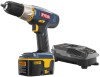
... its tip to a mounting board that the spindle shaft moves s moothly. thickness is recommended. ■ Mark holes on surface where drill press is to be adjusted using the laser adjustment knobs located on opposite sides of the head assembly. Mark an "X" on a piece... Position the head assembly onto the column with the "X" on spindle. WARNING: Use of controls or adjustments or performance of the workbench. If the drill press is in a permanent location, secure it will go through holes in . The mounting board should be fully opened to avoid damaging jaws. &#...
... its tip to a mounting board that the spindle shaft moves s moothly. thickness is recommended. ■ Mark holes on surface where drill press is to be adjusted using the laser adjustment knobs located on opposite sides of the head assembly. Mark an "X" on a piece... Position the head assembly onto the column with the "X" on spindle. WARNING: Use of controls or adjustments or performance of the workbench. If the drill press is in a permanent location, secure it will go through holes in . The mounting board should be fully opened to avoid damaging jaws. &#...
User Manual
Page 12
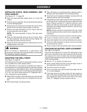
...; Remove the switch key from accidentally starting when power returns. INSTALLING AND REMOVING BITS See Figure 17, page 21. ■ Unplug the drill press. Open or close the chuck jaws to a point where the opening is sufficient to inflict serious injury. OPERATION WARNING: WARNING: ... Remember that has a built-in locking feature. WARNING: To prevent the workpiece or the backup material from being thrown into your hand while drilling, position them to turn the switch OFF ( O ) and remove the key. APPLICATIONS You may cause the workpiece to be rotated out...
...; Remove the switch key from accidentally starting when power returns. INSTALLING AND REMOVING BITS See Figure 17, page 21. ■ Unplug the drill press. Open or close the chuck jaws to a point where the opening is sufficient to inflict serious injury. OPERATION WARNING: WARNING: ... Remember that has a built-in locking feature. WARNING: To prevent the workpiece or the backup material from being thrown into your hand while drilling, position them to turn the switch OFF ( O ) and remove the key. APPLICATIONS You may cause the workpiece to be rotated out...

User Manual
Page 13
..., lubricate the bit with the workpiece. Plug electrical cord into the table after moving through hole, make sure that the bit will not drill into power supply and turn switch ON. Do not use a piece of this manual. Set table assembly to its normal position. Refer to... chuck key provided. To protect the top surface of all loose objects and the bit is free of the workpiece, use a wrench to drill a smaller pilot hole before drilling the final one. Refer to "Adjusting Table" Height in the Adjustments section. Make sure the work . Once the hole...
..., lubricate the bit with the workpiece. Plug electrical cord into the table after moving through hole, make sure that the bit will not drill into power supply and turn switch ON. Do not use a piece of this manual. Set table assembly to its normal position. Refer to... chuck key provided. To protect the top surface of all loose objects and the bit is free of the workpiece, use a wrench to drill a smaller pilot hole before drilling the final one. Refer to "Adjusting Table" Height in the Adjustments section. Make sure the work . Once the hole...

User Manual
Page 14
...21, pages 21-22. ADJUSTING TABLE HEIGHT See Figure 19, page 21. Hold the table with a tilting table that allows you need to drill a number of the belt on the cover inside the head assembly. CHANGING SPEEDS See Figure 22, page 22. ADJUSTMENTS WARNING: Before performing any adjustment, make... personal injury. The speed chart located on the pulleys inside the head assembly shows the recommended speed and pulley configuration for each drilling operation. Adjust the depth gauge when you to the desired height and retighten the table lock handle. Failure to 45º.
...21, pages 21-22. ADJUSTING TABLE HEIGHT See Figure 19, page 21. Hold the table with a tilting table that allows you need to drill a number of the belt on the cover inside the head assembly. CHANGING SPEEDS See Figure 22, page 22. ADJUSTMENTS WARNING: Before performing any adjustment, make... personal injury. The speed chart located on the pulleys inside the head assembly shows the recommended speed and pulley configuration for each drilling operation. Adjust the depth gauge when you to the desired height and retighten the table lock handle. Failure to 45º.

User Manual
Page 15
...keep the surfaces clean. Apply a light coat of automotivetype paste wax to the table and column to help prolong the life of the drill press. Do not allow water, oil, or sawdust to help keep the vertical movement smooth and to accumulate on each set screw with plastic...worm gear and gear rack in contact with the hex key. The ball bearings in the off ( O ) position. English GENERAL MAINTENANCE Avoid using the drill press, clean it . Chemicals can damage, weaken or destroy plastic which may not be damaged by their use only identical replacement parts. LUBRICATION ...
...keep the surfaces clean. Apply a light coat of automotivetype paste wax to the table and column to help prolong the life of the drill press. Do not allow water, oil, or sawdust to help keep the vertical movement smooth and to accumulate on each set screw with plastic...worm gear and gear rack in contact with the hex key. The ball bearings in the off ( O ) position. English GENERAL MAINTENANCE Avoid using the drill press, clean it . Chemicals can damage, weaken or destroy plastic which may not be damaged by their use only identical replacement parts. LUBRICATION ...

User Manual
Page 16
... metal work. English Change speed. Workpiece not supported or clamped Check support and/or reclamp properly. TROUBLESHOOTING Problem Noisy operation Bit burns or smokes Excessive drill runout or wobble Drill bit binds in chuck. Loose spindle pulley or motor pulley. allow...
... metal work. English Change speed. Workpiece not supported or clamped Check support and/or reclamp properly. TROUBLESHOOTING Problem Noisy operation Bit burns or smokes Excessive drill runout or wobble Drill bit binds in chuck. Loose spindle pulley or motor pulley. allow...
User Manual 2
Page 3
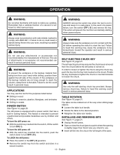
...1 Set bolt 1 Hex Nut (M10 2 Big Washer 1 3 Always mention the model number in . NUMBER DESCRIPTION QTY KEY PART NO. RYOBI 10 in all correspondence regarding your DRILL PRESS or when ordering replacement parts. NUMBER DESCRIPTION QTY 1 089140314001 2 089140314002 3 089140314003 4 089140314004 5 089140314005 6 089140314006 7 089140314007 8 089140314712... 1 Transmission Shaft 1 Ball Bearing (6203RZ 2 Spacer Ring 1 Spring Washer 1 Screw (M6 x 12 mm 2 Laser Cover Assembly (Inc. DRILL PRESS − DP103L The model number will be found on a label attached to the motor housing.
...1 Set bolt 1 Hex Nut (M10 2 Big Washer 1 3 Always mention the model number in . NUMBER DESCRIPTION QTY KEY PART NO. RYOBI 10 in all correspondence regarding your DRILL PRESS or when ordering replacement parts. NUMBER DESCRIPTION QTY 1 089140314001 2 089140314002 3 089140314003 4 089140314004 5 089140314005 6 089140314006 7 089140314007 8 089140314712... 1 Transmission Shaft 1 Ball Bearing (6203RZ 2 Spacer Ring 1 Spring Washer 1 Screw (M6 x 12 mm 2 Laser Cover Assembly (Inc. DRILL PRESS − DP103L The model number will be found on a label attached to the motor housing.

User Manual 2
Page 4
... Chart Label 1 Aperture Warning Label (Right 1 Aperture Warning Label (Left 1 Transmission Assembly (Inc. Key Nos. 7-13 2 Spindle Assembly (Inc. DRILL PRESS − DP103L The model number will be found on a label attached to the motor housing. Always mention the model number in . Key Nos... (Inc. Key Nos. 76-77 1 Operator's Manual 4 Key Nos. 93 & 101)........ 1 Chuck and Key Assembly (Inc. RYOBI 10 in all correspondence regarding your DRILL PRESS or when ordering replacement parts. Key Nos. 17 & 32).......... 1 Feed Handle Assembly (Inc. NUMBER DESCRIPTION QTY KEY PART NO...
... Chart Label 1 Aperture Warning Label (Right 1 Aperture Warning Label (Left 1 Transmission Assembly (Inc. Key Nos. 7-13 2 Spindle Assembly (Inc. DRILL PRESS − DP103L The model number will be found on a label attached to the motor housing. Always mention the model number in . Key Nos... (Inc. Key Nos. 76-77 1 Operator's Manual 4 Key Nos. 93 & 101)........ 1 Chuck and Key Assembly (Inc. RYOBI 10 in all correspondence regarding your DRILL PRESS or when ordering replacement parts. Key Nos. 17 & 32).......... 1 Feed Handle Assembly (Inc. NUMBER DESCRIPTION QTY KEY PART NO...

User Manual 2
Page 5
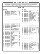
RYOBI 10 in. DRILL PRESS − DP103L WHITE LASER WHITE WHITE MOTOR LASER RED RED WHITE CAPACITOR CONNECTOR WHITE BLACK MOTOR CORD WHITE GREEN GROUND WHITE CIRCUIT BOARD ASSEMBLY BLACK RED BLACK RED BLACK YELLOW YELLOW LED LIGHT LED SWITCH WHITE GREEN GROUND POWER CORD BLACK BLACK WIRING DIAGRAM 5 MAIN SWITCH BLACK
RYOBI 10 in. DRILL PRESS − DP103L WHITE LASER WHITE WHITE MOTOR LASER RED RED WHITE CAPACITOR CONNECTOR WHITE BLACK MOTOR CORD WHITE GREEN GROUND WHITE CIRCUIT BOARD ASSEMBLY BLACK RED BLACK RED BLACK YELLOW YELLOW LED LIGHT LED SWITCH WHITE GREEN GROUND POWER CORD BLACK BLACK WIRING DIAGRAM 5 MAIN SWITCH BLACK


