
User Manual
Page 3
...use damaged or incorrect blade washers or bolt. Position your body to either side of operation. Large panels tend to a stable platform. CIRCULAR SAW SAFETY WARNINGS CUTTING PROCEDURES DANGER: Keep hands away from the work properly to jump backwards, but not in your hands or across your ... or straight edge guide. This improves the accuracy of cut for operations different from the blade below the workpiece. Never hold the saw motionless in the material until the blade comes to a complete stop. Kickback is restarted. Support large panels to control. ...
...use damaged or incorrect blade washers or bolt. Position your body to either side of operation. Large panels tend to a stable platform. CIRCULAR SAW SAFETY WARNINGS CUTTING PROCEDURES DANGER: Keep hands away from the work properly to jump backwards, but not in your hands or across your ... or straight edge guide. This improves the accuracy of cut for operations different from the blade below the workpiece. Never hold the saw motionless in the material until the blade comes to a complete stop. Kickback is restarted. Support large panels to control. ...
User Manual
Page 4
... using this rule will reduce the risk of serious personal injury. Protect your extension cord is dusty. Do not operate the saw to walk backwards, cutting whatever is accidentally dropped, lower guard may operate sluggishly due to carry the current your product will reduce the ...is unstable and may use the next heavier gauge. Raise the lower guard with ANSI Z87.1. CIRCULAR SAW SAFETY WARNINGS their own weight. Supports must be tight and secure before placing saw is in all other part that is released. Unsharpened or improperly set blades produce narrow kerf ...
... using this rule will reduce the risk of serious personal injury. Protect your extension cord is dusty. Do not operate the saw to walk backwards, cutting whatever is accidentally dropped, lower guard may operate sluggishly due to carry the current your product will reduce the ...is unstable and may use the next heavier gauge. Raise the lower guard with ANSI Z87.1. CIRCULAR SAW SAFETY WARNINGS their own weight. Supports must be tight and secure before placing saw is in all other part that is released. Unsharpened or improperly set blades produce narrow kerf ...
User Manual
Page 9
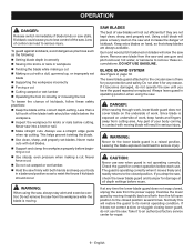
... contact with a dull, gummed up, or improperly set blade Supporting the workpiece incorrectly Forcing a cut . If it to the circular saw firmly with both hands and keep hands and fingers away from the power supply. Never force a cut. Do not cut warped or wet .... BLADE GUARD SYSTEM See Figure 8, page 16. Never make cuts with dull blades. Support and clamp the workpiece properly before reuse. SAW BLADES The best of kickback, follow these accumulations. If it moves freely and readily returns to remove these safety practices: Keep ...
... contact with a dull, gummed up, or improperly set blade Supporting the workpiece incorrectly Forcing a cut . If it to the circular saw firmly with both hands and keep hands and fingers away from the power supply. Never force a cut. Do not cut warped or wet .... BLADE GUARD SYSTEM See Figure 8, page 16. Never make cuts with dull blades. Support and clamp the workpiece properly before reuse. SAW BLADES The best of kickback, follow these accumulations. If it moves freely and readily returns to remove these safety practices: Keep ...
User Manual
Page 13
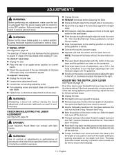
... could lead to wear, the depth lock lever may move when released. 13 - To adjust 0° bevel stop: Unplug the circular saw. Loosen bevel adjustment knob. Loosen hex nut securing adjusting screw. Turn adjusting screw and adjust base until it ... The laser will activate without having the bevel adjustment knob securely tightened can result in hazardous radiation exposure. Unplug the saw. REMOVE the blade before adjusting the laser. Clamp a straight edge to secure. Insert a flathead ...
... could lead to wear, the depth lock lever may move when released. 13 - To adjust 0° bevel stop: Unplug the circular saw. Loosen bevel adjustment knob. Loosen hex nut securing adjusting screw. Turn adjusting screw and adjust base until it ... The laser will activate without having the bevel adjustment knob securely tightened can result in hazardous radiation exposure. Unplug the saw. REMOVE the blade before adjusting the laser. Clamp a straight edge to secure. Insert a flathead ...
User Manual 2
Page 2
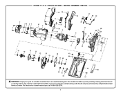
CIRCULAR SAW - RYOBI 7-1/4 in damages to the double insulation system possibly causing electrical shock or electrocution. For the service center nearest you call 1-800-525-2579. 2 MODEL NUMBER ... 48 49 20 45 42 43 44 35 50 57 WARNING: Improper repair of your tool requires safety testing and should only be performed by a Ryobi Authorized Service Center. Any repairs requiring disassembly of a double insulated tool can result in .
CIRCULAR SAW - RYOBI 7-1/4 in damages to the double insulation system possibly causing electrical shock or electrocution. For the service center nearest you call 1-800-525-2579. 2 MODEL NUMBER ... 48 49 20 45 42 43 44 35 50 57 WARNING: Improper repair of your tool requires safety testing and should only be performed by a Ryobi Authorized Service Center. Any repairs requiring disassembly of a double insulated tool can result in .
User Manual 2
Page 3
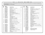
... 1 Lower Blade Guard 1 Retaining Ring 1 Inner Flange Bushing 1 Outer Blade Washer 1 Blade Screw (5/16-18 x 9/16 in all correspondence regarding your CIRCULAR SAW or when ordering parts. Key Nos. 45-50 1 Screw (M3.5 x 16 mm, Pan Hd 3 Laser Cover 1 Compression Spring 1 Laser Assembly 1... x 50, Type B Pan Hd.)....... 2 Warning Label 1 Volute 1 Spindle Lock 1 Compression Spring 1 Lock Nut (M5 1 Upper Blade Guard Assembly (Inc. RYOBI 7-1/4 in ., 20 Tooth Carbide Tipped).... 1 Laser Label 1 Clamp 2 Edge Guide Kit (Optional) Dust Nozzle Kit (Optional) Operator's Manual
... 1 Lower Blade Guard 1 Retaining Ring 1 Inner Flange Bushing 1 Outer Blade Washer 1 Blade Screw (5/16-18 x 9/16 in all correspondence regarding your CIRCULAR SAW or when ordering parts. Key Nos. 45-50 1 Screw (M3.5 x 16 mm, Pan Hd 3 Laser Cover 1 Compression Spring 1 Laser Assembly 1... x 50, Type B Pan Hd.)....... 2 Warning Label 1 Volute 1 Spindle Lock 1 Compression Spring 1 Lock Nut (M5 1 Upper Blade Guard Assembly (Inc. RYOBI 7-1/4 in ., 20 Tooth Carbide Tipped).... 1 Laser Label 1 Clamp 2 Edge Guide Kit (Optional) Dust Nozzle Kit (Optional) Operator's Manual
User Manual 2
Page 4
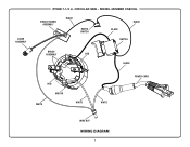
MODEL NUMBER CSB135L CIRCUIT BOARD ASSEMBLY BLACK MICRO SWITCH BLACK BLACK SWITCH BRUSH ASSEMBLY RED BLACK RED MOTOR WHITE WHITE WHITE POWER CORD WIRE NUT WIRING DIAGRAM 4 CIRCULAR SAW - LASER ASSEMBLY RYOBI 7-1/4 in.
MODEL NUMBER CSB135L CIRCUIT BOARD ASSEMBLY BLACK MICRO SWITCH BLACK BLACK SWITCH BRUSH ASSEMBLY RED BLACK RED MOTOR WHITE WHITE WHITE POWER CORD WIRE NUT WIRING DIAGRAM 4 CIRCULAR SAW - LASER ASSEMBLY RYOBI 7-1/4 in.

